MITSUBISHI 3000GT 1991 Service Manual
Manufacturer: MITSUBISHI, Model Year: 1991, Model line: 3000GT, Model: MITSUBISHI 3000GT 1991Pages: 1146, PDF Size: 76.68 MB
Page 151 of 1146
FUEL SYSTEM -On-vehicle Inspection of MPI Components13-45
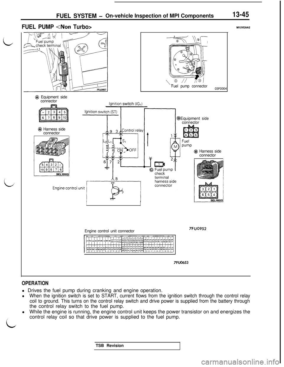
FUEL PUMP
@ Equipment side
connector
@ Harness side
connector
lqnition switch (IG,i
LL--- /A&
\“// //@JFuel pump connector
Engine control unit connectorEquipment
connectorside
@ Harness side
connector
7FUO653
7FUO952
M13YEAA2
OPERATIONl Drives the fuel pump during cranking and engine operation.
lWhen the ignition switch is set to START, current flows from the ignition switch through the control relay
coil to ground. This turns on the control relay switch and drive power is supplied from the battery throughthe control relay switch to the fuel pump.
lWhile the engine is running, the engine control unit keeps the power transistor on and energizes the
icontrol relay coil so that drive power is supplied to the fuel pump.
LTSB Revision
Page 152 of 1146
13-46FUEL SYSTEM - On-vehicle Inspection of MPI Components
INSPECTIONUsing Multi-use Tester
FunctionItem No.DriveCheck condition
Check contentNormal statedActuator test 07
Fuel pump isl Engine cranking
Hold return hose withPulsation is felt
driven to cir-l Forced drive of fuelculate fuelfingers to feel pulsation
pump
Check is made forindicating fuel flow
above two conditions
Listen to pump operating
sound near fuel tankOperating sound isheard
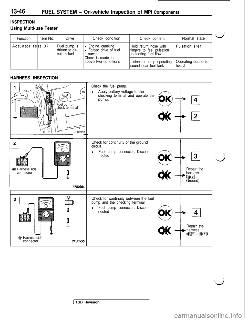
HARNESS INSPECTION
check terminal
7FUO954
@ Harness side
connector7FUO955
Check the fuel pump.l
Apply battery voltage to thechecking terminal and operate the
w-w
Check for continuity of the ground
circuit.l
Fuel pump connector: Discon-
nected
Repair the
harness.
@FJ-Ground)
Check for continuity between the fuelpump and the checking terminal.l
Fuel pump connector: Discon-
nectedcl4
Repair the
harness.
@vJ-@g)
1 TSB Revision
Page 153 of 1146
FUEL SYSTEM - On-vehicle inspection of MPI Components
@ Harness side
connector6
1
@ Harness side
connector
77FUO475
-
Engine controlunit harnessside connector
Q Harness side
-1
=7FUO476
9 Harnessside
connec-
tor
@ Harness side connector
7FUO956
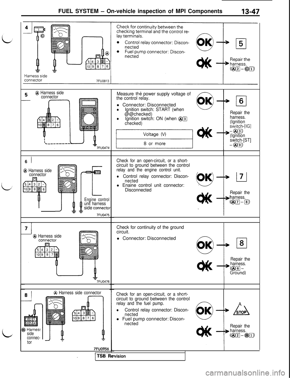
Measure th& power supply voltage of
the control relay.l Connector: Disconnected
OK
lIgnition switch: START (when0
@@checked)lIgnition switch: ON (when @@
checked)
cl6
t
Repair the
harness.
(Ignition
switch-[IGI
- @El)
(Ignition
switch-[ST]
- @El)
Check for an open-circuit, or a short-
circuit to ground between the controlrelay and the engine control unit.
lControl relay connector: Discon-nectedl Enaine control unit connector:
Disconnected
Repair the
harness.
@El-lg
Check for continuity of the ground
circuit.l Connector: Disconnected
Repair the
harness.
L%n~)
Check for an open-circuit, or a short-circuit to ground between the controlrelay and the fuel pump.A
lControl relay connector: Discon-nected(OK)+ Adl Fuel pump connector:
Discon-netted
Repair the
harness.
@I@-@g)
I
vision
Page 154 of 1146
13-48FUEL SYSTEM - On-vehicle Inspection of MPI Components
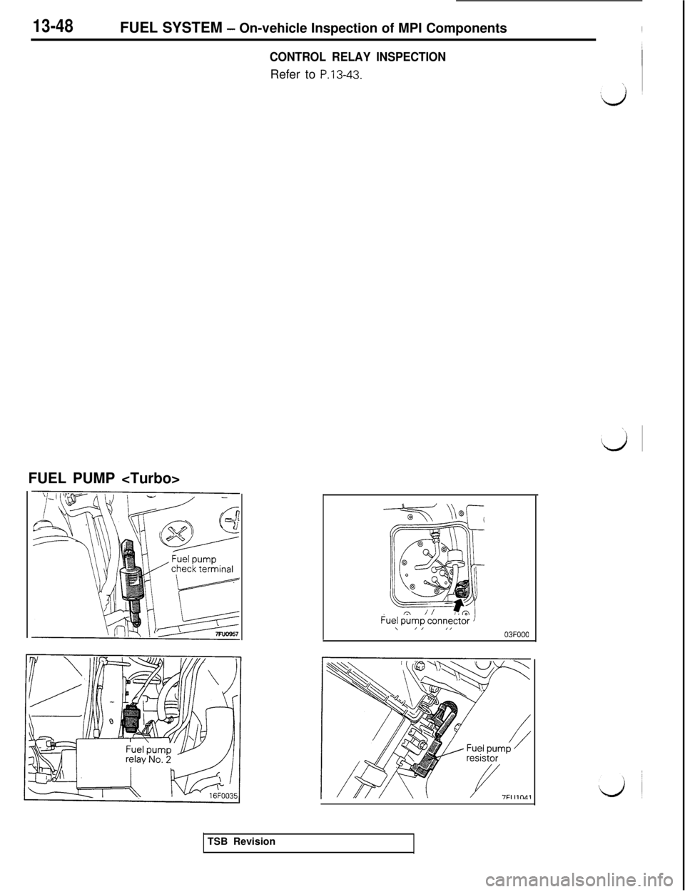
CONTROL RELAY INSPECTIONRefer to
P.13-43.FUEL PUMP
\/I ,,03FOOO
TSB Revision
Page 155 of 1146
![MITSUBISHI 3000GT 1991 Service Manual FUEL SYSTEM - On-vehicle Inspection of MPI Components
13-49 i
Ignition switch [IG]
Ignition switch [ST]
@ Equipment side
connector9 3Control reta)
;i.
L Ll
@ Harness side
connector
Enaine control unit MITSUBISHI 3000GT 1991 Service Manual FUEL SYSTEM - On-vehicle Inspection of MPI Components
13-49 i
Ignition switch [IG]
Ignition switch [ST]
@ Equipment side
connector9 3Control reta)
;i.
L Ll
@ Harness side
connector
Enaine control unit](/img/19/57085/w960_57085-154.png)
FUEL SYSTEM - On-vehicle Inspection of MPI Components
13-49 i
Ignition switch [IG]
Ignition switch [ST]
@ Equipment side
connector9 3Control reta)
;i.
L Ll
@ Harness side
connector
Enaine control unitEquipment side
connector
M-ii
Resistorw(for fuel pump)
Equipment side
connector
II &A
8 A21
@ Equipment
side@I Harness side
connector
connector
M
‘r
Y
2
7
Y
Fuelpump
-JFuel pumpcheck terminal
7FUO959Engine control unit connector
7FUO653
idTSB Revision
Page 156 of 1146
13-50FUEL SYSTEM - 0
n-vehicle Inspection of MPI Components
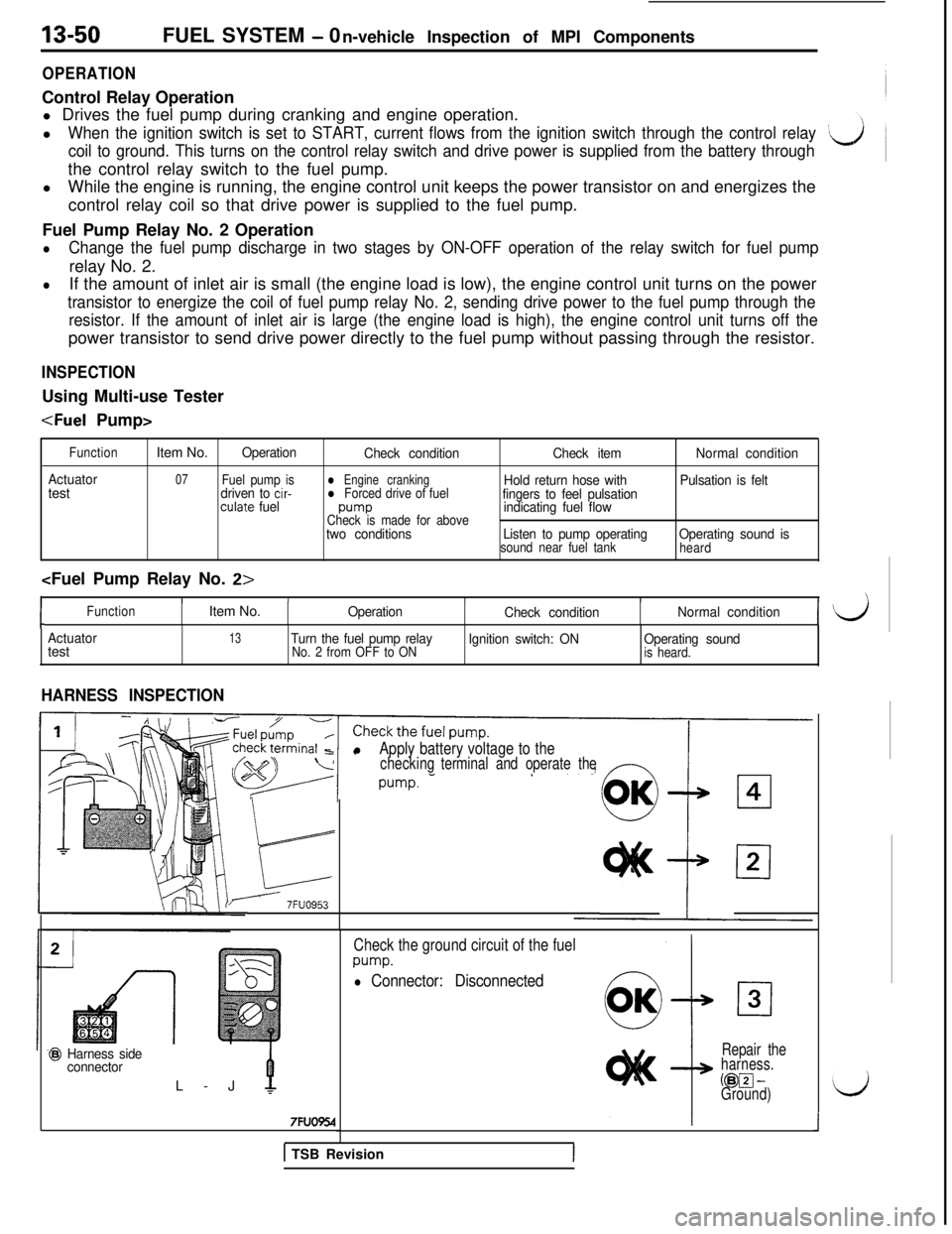
OPERATIONControl Relay Operation
l Drives the fuel pump during cranking and engine operation.
l
When the ignition switch is set to START, current flows from the ignition switch through the control relay
coil to ground. This turns on the control relay switch and drive power is supplied from the battery throughthe control relay switch to the fuel pump.
lWhile the engine is running, the engine control unit keeps the power transistor on and energizes the
control relay coil so that drive power is supplied to the fuel pump.
Fuel Pump Relay No. 2 Operation
lChange the fuel pump discharge in two stages by ON-OFF operation of the relay switch for fuel pumprelay No. 2.
lIf the amount of inlet air is small (the engine load is low), the engine control unit turns on the power
transistor to energize the coil of fuel pump relay No. 2, sending drive power to the fuel pump through the
resistor. If the amount of inlet air is large (the engine load is high), the engine control unit turns off thepower transistor to send drive power directly to the fuel pump without passing through the resistor.
INSPECTIONUsing Multi-use Tester
Function
ActuatortestItem No.
Operation
Check conditionCheck itemNormal condition
07Fuel pump isdriven to cir-l Engine crankingHold return hose withl Forced drive of fuelPulsation is felt
culate fuelfingers to feel pulsationpump
Check is made for aboveindicating fuel flow
two conditionsListen to pump operating
sound near fuel tankOperating sound isheard
I/IIII
cFunctionItem No.Operation
Check conditionNormal condition
Actuatortest
13Turn the fuel pump relayNo. 2 from OFF to ONIgnition switch: ONOperating soundis heard.
HARNESS INSPECTION
k
J------ 7FUO953
lApply battery voltage to thecheckingterminal and operate the
Check the ground circuit of the fuel
pump.
l Connector: Disconnected
@I Harness side
connectorL-J
7FUO554
Repair the
harness.
@pJ-Ground)
J
1 TSB Revision
Page 157 of 1146
FUEL SYSTEM- On-vehicle Inspection of MPI Components13-51
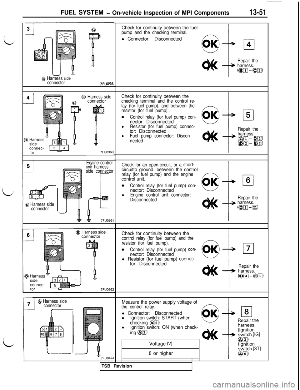
Check for continuity between the fuelpump and the checking terminal.-I
l Connector: Disconnected
@N+ 14
Repair the
harness.
(@lig-@g)
@ Harness srdeconnector7FUO95:
Check for continuity between thechecking terminal and the control re-
lay (for fuel pump), and between the
resistor (for fuel pump).
0Control relay (for fuel pump) con-nector: DisconnectedlResistor (for fuel pump) connec-tor: DisconnectedlFuel pump connector: Discon-
nected
Harness side
connector
7FUO960
0
OK
Repair the
harness.
(Cm- Da)!~m-- E@J)8 8
Enaine controlCheck for an open-circuit, or a short-circuitto ground, between the controlrelay (for fuel pump) and the enginecontrol unit.
0Control relay (for fuel pump) con-nector: Disconnected
un? harness
side connector
lEngine control unit connector:
DisconnectedRepair the
harness.
(@J-m@ Harness side
connector
Check for continuity between thecontrol relay (for fuel pump) and the
resistor (for fuel pump).
0Control relay (for fuel pump) con-nectar: Disconnectedl Resistor (for fuel pump) connec-tor: DisconnectedRepair the
harness.
(@pJ-@iJ)
7FUO962
Measure the power supply voltage ofthe control relay.
@I Harness side
connector
rl Connector: DisconnectedlIgnition switch: START (when
checking
@@IlIgnition switch: ON (when check-
ing
@@IVoltage
(VI8 or higher
1 ‘7FUO47fITSB Revision
Page 158 of 1146
13-52FUEL SYSTEM - 0
n-vehicle Inspection of MPI Components
-i8
@ Harness side
connector
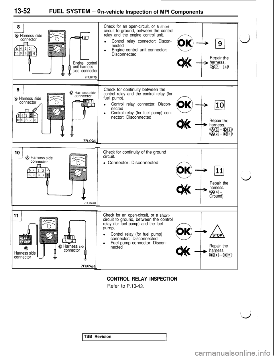
Check for an open-circuit, or a short-circuit to ground, between the controlrelay and the engine control unit.l
Control relay connector: Discon-
nectedl
Engine control unit connector:
Disconnected
Engine controlunit harness
side connector
7FUO475g
/Check for continuity between thecontrol relay and the control relay (for
fuel pump).l
Control relay connector: Discon-
nectedl
Control relay (for fuel pump) con-nector: Disconnected
zonnector8 Harness side
connector
/
7FUO96:
T
Check for continuity of the ground
circuit.l Connector: Disconnected
!
Repair the
harness.
@pJ-Ground)
7FUO476
Check for an open-circuit, or a short-circuit to ground, between the controlrelay (for fuel pump) and the fuel
pump.l
Control relay (for fuel pump)connector: DisconnectedlFuel pump connector: Discon-nectedRepair the
harness.
(@@-@lTJ)
@I Harness sidtconnector@Harness side
connector
I7FUO964
CONTROL RELAY INSPECTIONRefer to
P.13-43.TSB Revision
1
Page 159 of 1146
FUEL SYSTEM - On-vehicle Inspection of MPI Components13-53
7FU104:
Fuel pump /resistor
///I/ \\/7FU1041
7FU1043
I-TSB I
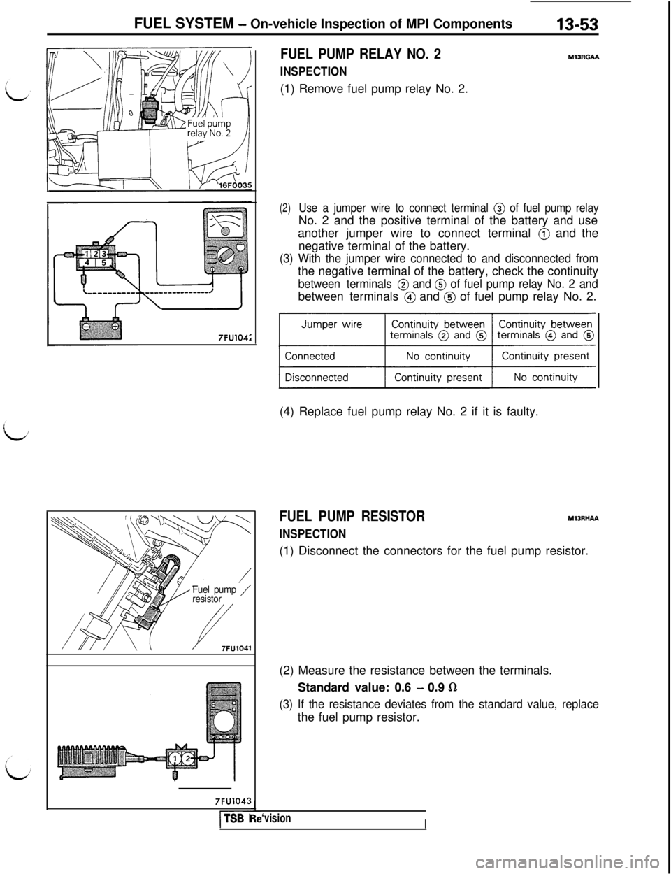
FUEL PUMP RELAY NO. 2
INSPECTION(1) Remove fuel pump relay No. 2.
M13RGAh
(2)Use a jumper wire to connect terminal @ of fuel pump relayNo. 2 and the positive terminal of the battery and use
another jumper wire to connect terminal
@ and the
negative terminal of the battery.
(3) With the jumper wire connected to and disconnected fromthe negative terminal of the battery, check the continuity
between terminals @ and @ of fuel pump relay No. 2 andbetween terminals
@ and @ of fuel pump relay No. 2.
(4) Replace fuel pump relay No. 2 if it is faulty.
FUEL PUMP RESISTOR
INSPECTION
MlBRHAA(1) Disconnect the connectors for the fuel pump resistor.
(2) Measure the resistance between the terminals.
Standard value: 0.6
- 0.9 LR
(3) If the resistance deviates from the standard value, replacethe fuel pump resistor.
‘visionI
Page 160 of 1146
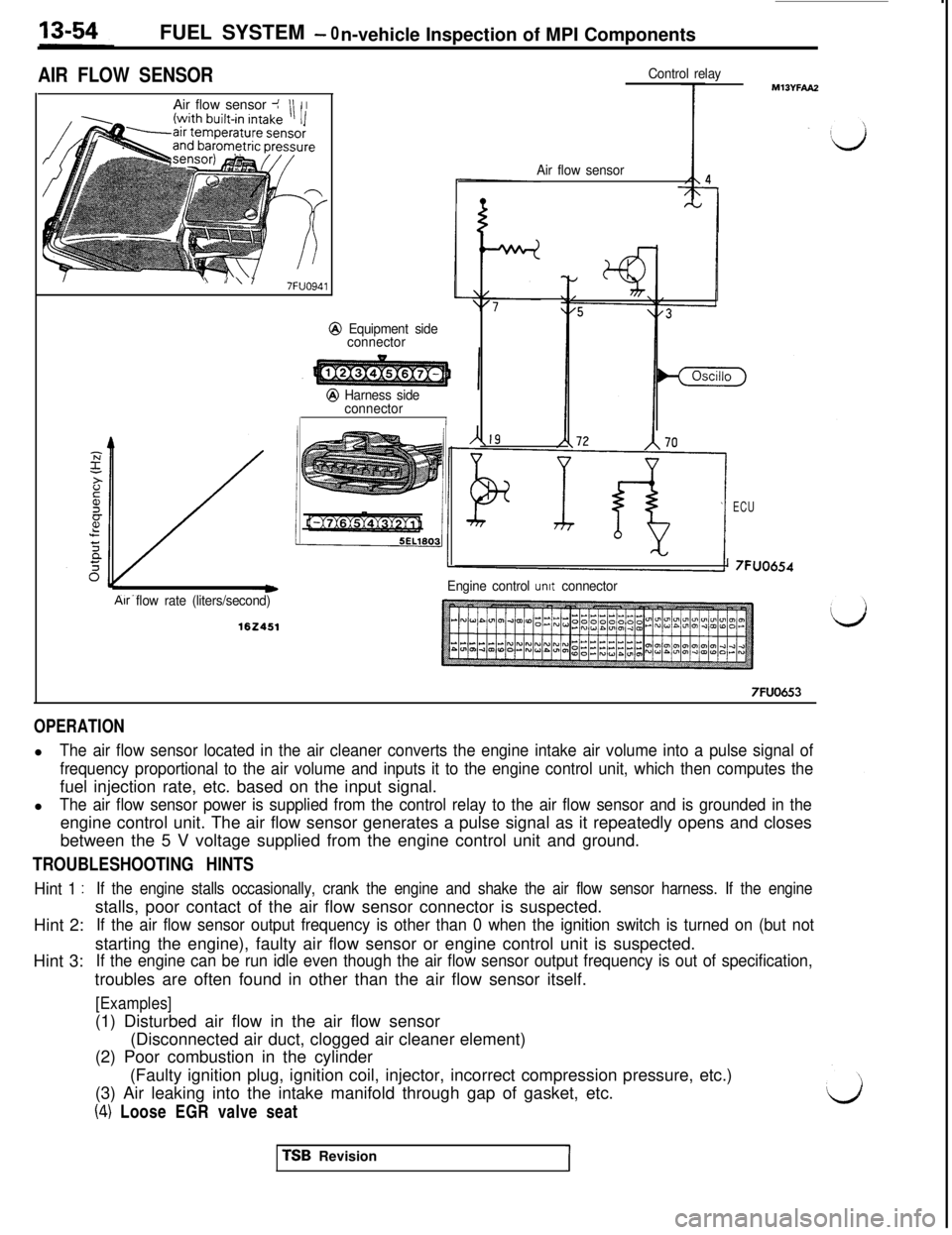
FUEL SYSTEM - 0
n-vehicle Inspection of MPI Components
AIR FLOW SENSORAir flow sensor J
III I
\I\Y7FUO941
@ Equipment side
connector
Air flow rate (liters/second)
@ Harness side
connector
I
Control relay
I
Air flow sensor
ECU
’ 7FUO654
Engine control
unit connector
7FUO653
OPERATIONl
The air flow sensor located in the air cleaner converts the engine intake air volume into a pulse signal of
frequency proportional to the air volume and inputs it to the engine control unit, which then computes thefuel injection rate, etc. based on the input signal.
l
The air flow sensor power is supplied from the control relay to the air flow sensor and is grounded in theengine control unit. The air flow sensor generates a pulse signal as it repeatedly opens and closes
between the 5 V voltage supplied from the engine control unit and ground.
TROUBLESHOOTING HINTS
Hint 1 :If the engine stalls occasionally, crank the engine and shake the air flow sensor harness. If the engineHint 2:stalls, poor contact of the air flow sensor connector is suspected.
If the air flow sensor output frequency is other than 0 when the ignition switch is turned on (but notHint 3:starting the engine), faulty air flow sensor or engine control unit is suspected.
If the engine can be run idle even though the air flow sensor output frequency is out of specification,troubles are often found in other than the air flow sensor itself.
[Examples](1) Disturbed air flow in the air flow sensor
(Disconnected air duct, clogged air cleaner element)
(2) Poor combustion in the cylinder
(Faulty ignition plug, ignition coil, injector, incorrect compression pressure, etc.)
(3) Air leaking into the intake manifold through gap of gasket, etc.
(4) Loose EGR valve seatTSB Revision