MITSUBISHI 3000GT 1991 Service Manual
Manufacturer: MITSUBISHI, Model Year: 1991, Model line: 3000GT, Model: MITSUBISHI 3000GT 1991Pages: 1146, PDF Size: 76.68 MB
Page 181 of 1146
FUEL SYSTEM - On-vehicle Inspection of MPI Components
L
L
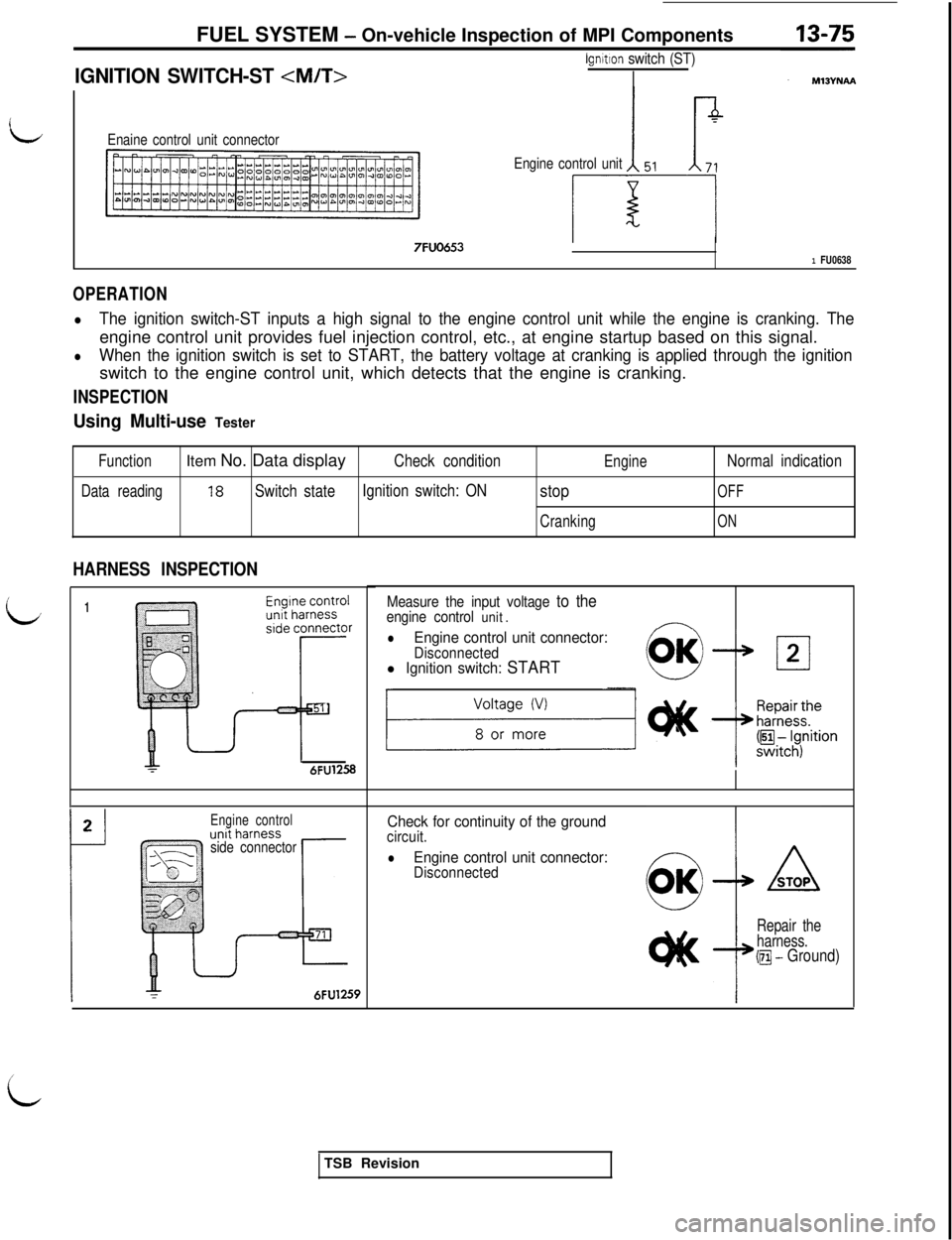
IGNITION SWITCH-ST
lgnitlon switch (ST)
I
Enaine control unit connector
7FUO653
Engine control unit
1 FU0638
OPERATION
lThe ignition switch-ST inputs a high signal to the engine control unit while the engine is cranking. Theengine control unit provides fuel injection control, etc., at engine startup based on this signal.
lWhen the ignition switch is set to START, the battery voltage at cranking is applied through the ignitionswitch to the engine control unit, which detects that the engine is cranking.
INSPECTION
Using Multi-use Tester
FunctionItem No. Data displayCheck conditionEngineNormal indication
Data reading18Switch stateIgnition switch: ONstopOFF
CrankingON
HARNESS INSPECTION
1
L6FU1258
2
1
Engine control
side connector
IY-6FU1259
Measure the input voltage to theengine control unit.nlEngine control unit connector:Disconnectedl Ignition switch: START
Check for continuity of the groundcircuit.
lEngine control unit connector:Disconnected
Repair the
harness.
(m - Ground)
iTSB Revision
Page 182 of 1146
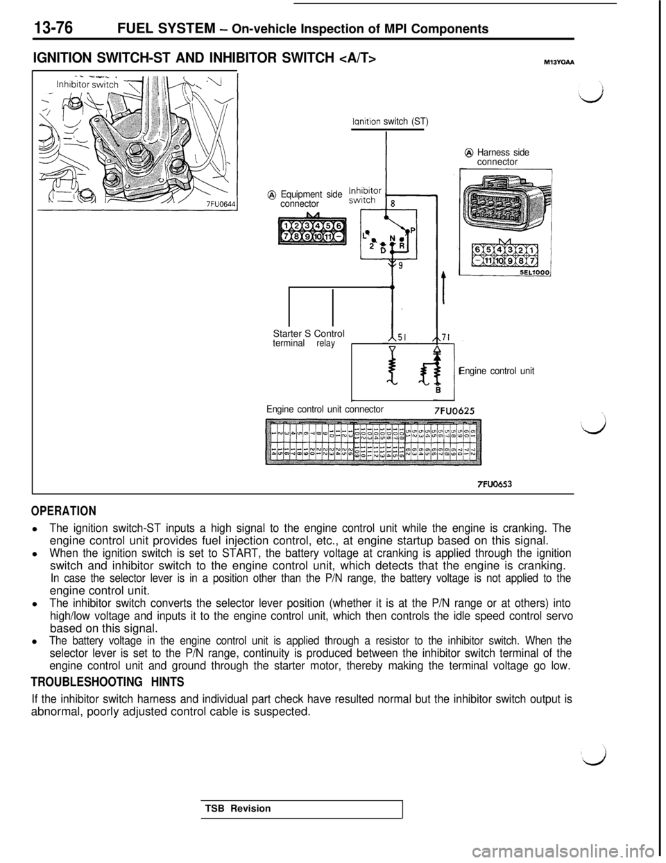
Page 183 of 1146
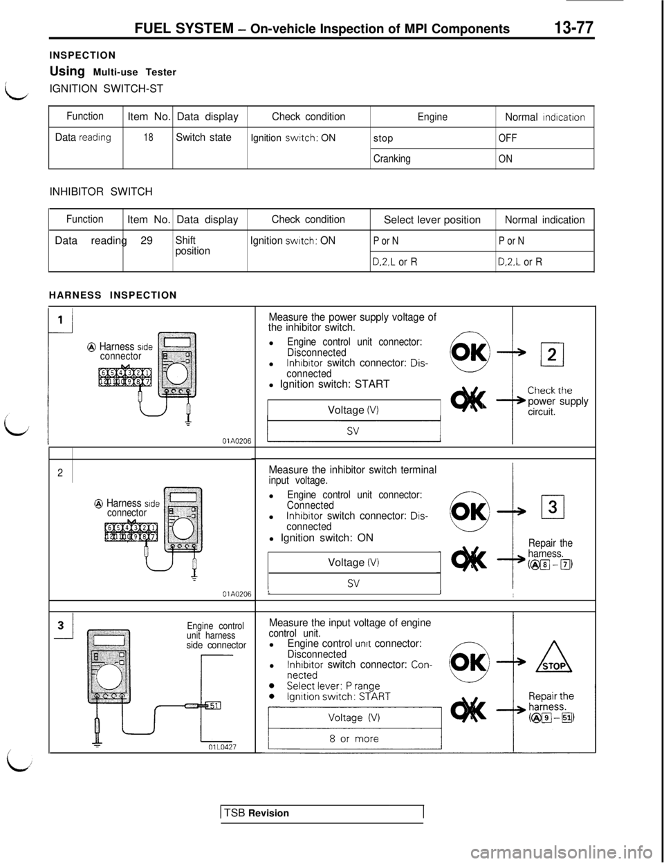
FUEL SYSTEM - On-vehicle Inspection of MPI Components13-77INSPECTION
Using Multi-use Tester
LIGNITION SWITCH-ST
FunctionItem No. Data displayCheck conditionEngineNormal rndrcation
Data reading18Switch stateIgnition switch: ON
stopOFF
CrankingONINHIBITOR SWITCH
FunctionItem No. Data displayCheck conditionSelect lever positionNormal indicationData reading 29
Shift
Ignition switch: ONP or NP or Nposition
D.2,L or RD.2.L or RHARNESS INSPECTION
@ Harness sideconnector
OlA0206
2
@ Harness srdeconnectorl
Engine control unit connector:
Connectedl
InhibItor switch connector: Dis-6a
L-J
cl3
connectedl Ignition switch: ON
Repair the
harness.Voltage
(VI@El - El)
OlA0206LII
Engine control
unit harness
side connector
Measure the power supply voltage of
the inhibitor switch.
-lEngine control unit connector:
Disconnectedl
lnhibrtor switch connector: Dis-
connectedl Ignition switch: START
Voltage
(V)
rLlltXK IlIt:Lpower supplycircuit.
Measure the inhibitor switch terminalinput voltage.
Measure the input voltage of enginecontrol unit.lEngine control unrt connector:DisconnectedlFer;it;r switch connector: Con-
1 TSB Revision
Page 184 of 1146
![MITSUBISHI 3000GT 1991 Service Manual 13-78FUEL SYSTEM - 0n-vehicleInspection of MPI Components
VEHICLE SPEED SENSORMIBYPM
Vehrcle speed sensor
(reed switch\)Speedometer
Terminal voltage
(V)
@ Equipment side
Vehicle speed [km/h (mph)]
16 MITSUBISHI 3000GT 1991 Service Manual 13-78FUEL SYSTEM - 0n-vehicleInspection of MPI Components
VEHICLE SPEED SENSORMIBYPM
Vehrcle speed sensor
(reed switch\)Speedometer
Terminal voltage
(V)
@ Equipment side
Vehicle speed [km/h (mph)]
16](/img/19/57085/w960_57085-183.png)
13-78FUEL SYSTEM - 0n-vehicleInspection of MPI Components
VEHICLE SPEED SENSORMIBYPM
Vehrcle speed sensor
(reed switch\)Speedometer
Terminal voltage
(V)
@ Equipment side
Vehicle speed [km/h (mph)]
162461
Engine control unit
7FUO925
Engine control unit connector7FUO653
OPERATION
lThe vehicle speed sensor which is located in the speedometer converts the vehicle speed into a pulse
signal and inputs it to the engine control unit, which then provides the idle speed control, etc. based on
this signal.
lThe vehicle speed sensor generates the vehicle speed signal by repeatedly opening and closing betweenthe voltage of about 5 V applied from the engine control unit and ground using a reed switch.
TROUBLESHOOTING HINTS
If there is an open or short circuit in the vehicle speed sensor signal circuit, the engine may stall when thevehicle is decelerated to stop.
HARNESS INSPECTION
unit harness
side connectorCheck the vehicle speed sensor out-
put circuit for continuity.
lEngine control unit connector:
Disconnected
lMove the vehicle.
TSB Revision
1
d
Page 185 of 1146
FUEL SYSTEM - On-vehicle lnwection of MPI ComDonents
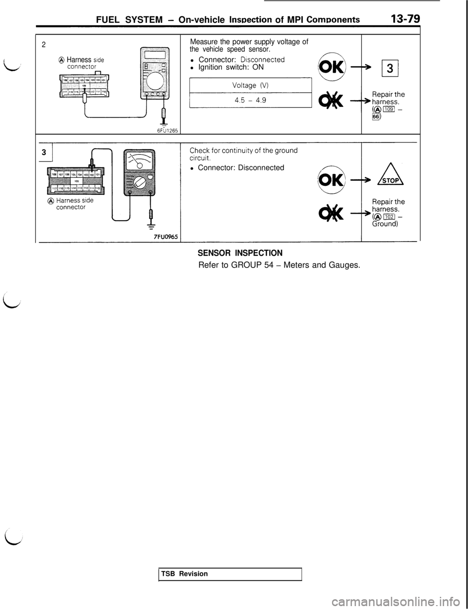
2Measure the power supply voltage ofthe vehicle speed sensor.
@ Harness sidel Connector: Dlsconnectedl Ignition switch: ON
8)
6FU1265l Connector: Disconnected
SENSOR INSPECTIONRefer to GROUP 54
- Meters and Gauges.
TSB Revision
Page 186 of 1146

13-80FUEL SYSTEM - 0
n-vehicle Inspection of MPI Components
POWER STEERING OIL PRESSURE SWITCHMlOYQAA
B
$-
Engine control unit
'107
@ Harness side
connector
ml-
Power steering oil
Pressure switch
7FUO536700-2.000 1.500-2.000(100-284) (213-284)Pressure [kPa (psi)]
0, l.oIu
OPERATIONl
The power steering oil pressure switch converts presence/absence of power steering load into low/high
voltage and inputs it to the engine control unit, which then controls the idle speed control servo based on
this signal.l The battery voltage in the engine control unit is applied through a resistor to the power steering oil
pressure switch. Steering operation causes the power steering oil pressure to increase, turning the
switch on. As a result, continuity is produced between the battery voltage applied and ground. This
causes the power steering oil pressure terminal voltage to go from high to low.
TSB Revision
Page 187 of 1146
FUEL SYSTEM- On-vehicle Inspection of MPI Components13-81
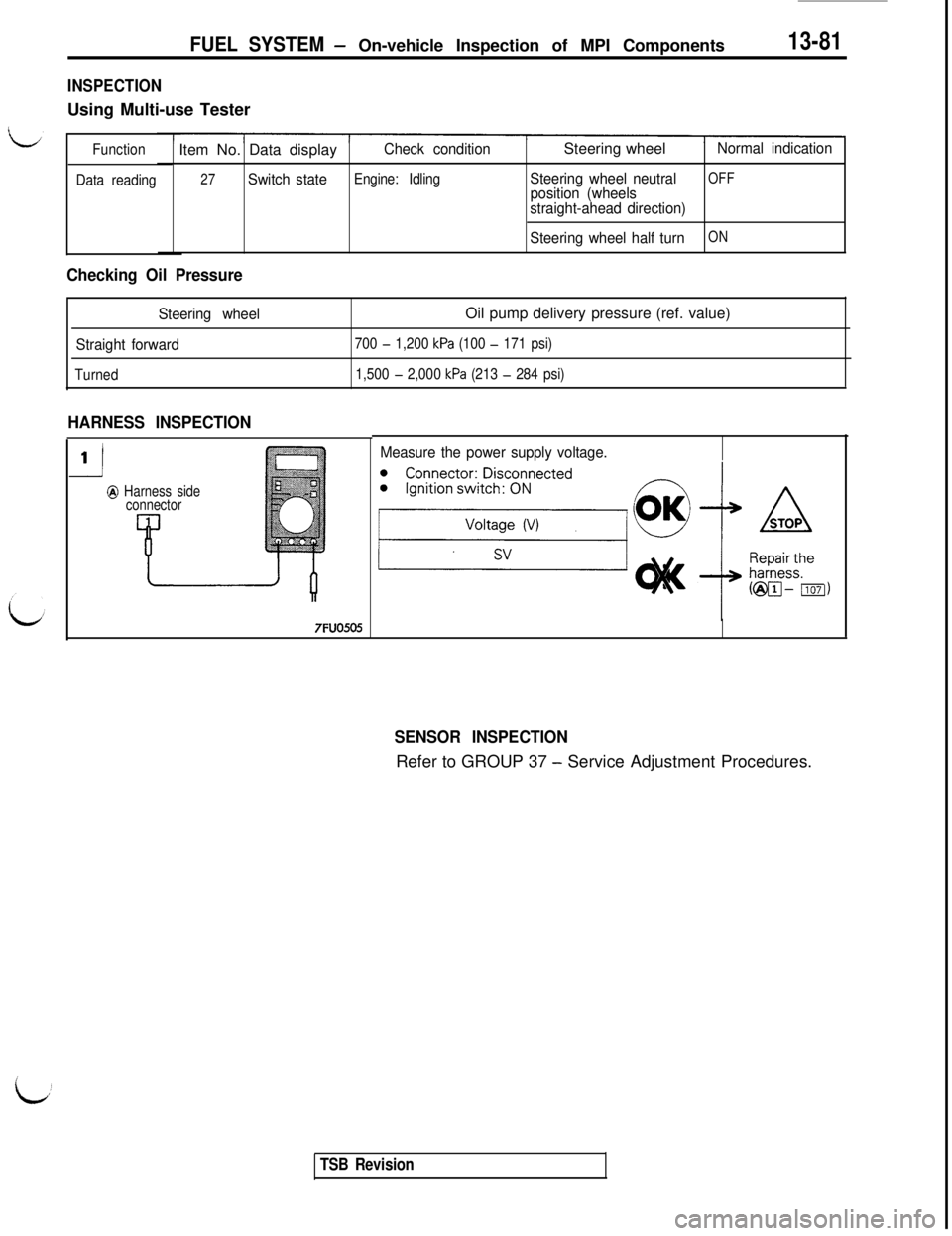
INSPECTIONUsing Multi-use Tester
Function
Data readingItem No. Data displayCheck conditionSteering wheelNormal indication
27Switch stateEngine: IdlingSteering wheel neutralOFFposition (wheels
straight-ahead direction)
Steering wheel half turn
ON
Checking Oil Pressure
Steering wheelOil pump delivery pressure (ref. value)
Straight forward700 - 1,200 kPa (100 - 171 psi)
Turned1,500
- 2,000 kPa (213 - 284 psi)
HARNESS INSPECTION
i1
@ Harness side
connector
Measure the power supply voltage.
SENSOR INSPECTIONRefer to GROUP 37
- Service Adjustment Procedures.
TSB Revision
Page 188 of 1146
13-82FUEL SYSTEM - On-vehicle Inspection of MPI Components
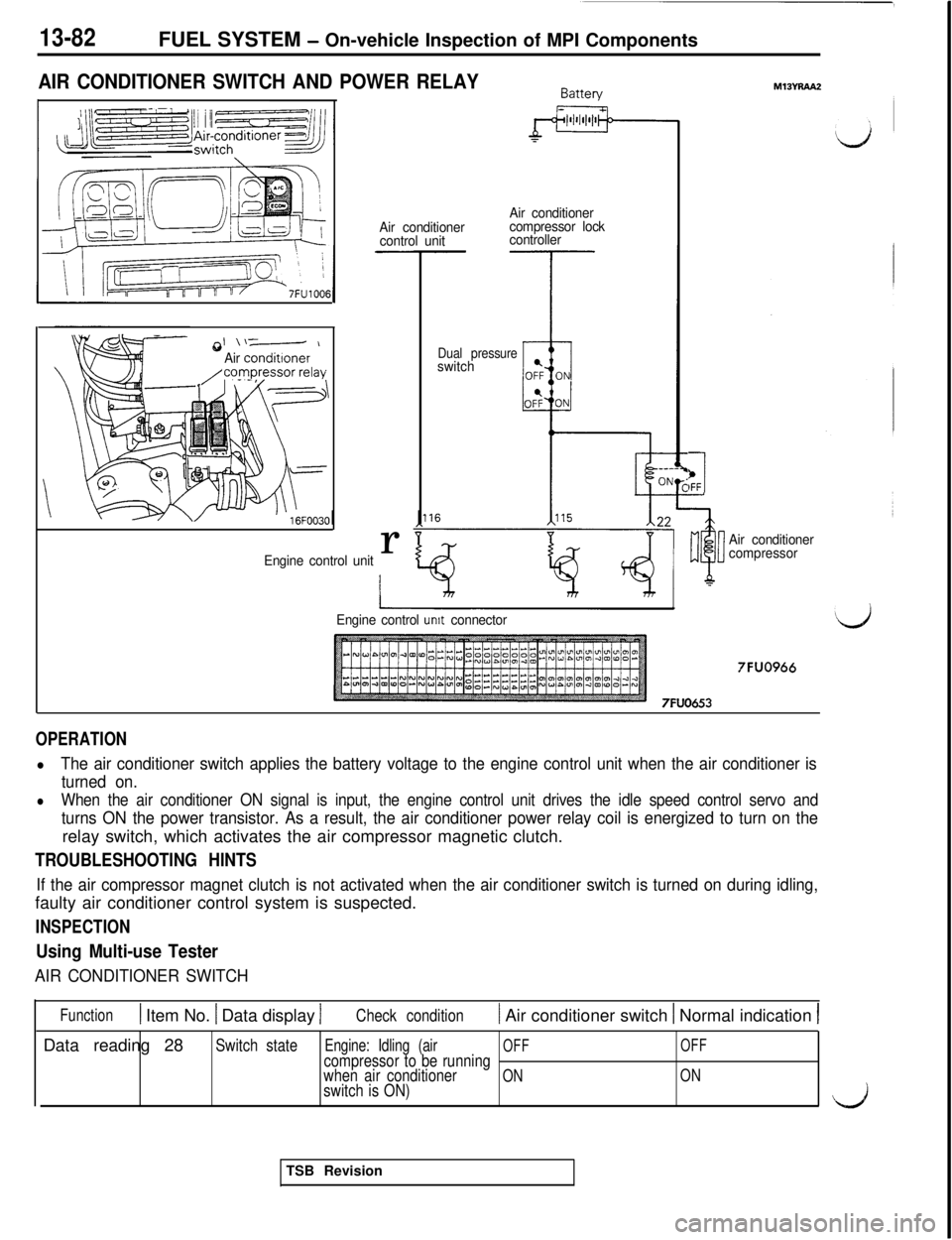
AIR CONDITIONER SWITCH AND POWER RELAY
\
*I \\-- \
Air conditronerAir conditioner
control unitAir conditioner
compressor lock
controllerr
Engine control unit
Dual pressureswitch
M13YRAA2
b1IFF
Air conditioner
compressor
Engine control
unit connector
7FUO966
7FUO653
OPERATION
lThe air conditioner switch applies the battery voltage to the engine control unit when the air conditioner is
turned on.
lWhen the air conditioner ON signal is input, the engine control unit drives the idle speed control servo and
turns ON the power transistor. As a result, the air conditioner power relay coil is energized to turn on therelay switch, which activates the air compressor magnetic clutch.
TROUBLESHOOTING HINTS
If the air compressor magnet clutch is not activated when the air conditioner switch is turned on during idling,faulty air conditioner control system is suspected.
INSPECTION
Using Multi-use Tester
AIR CONDITIONER SWITCH
Function1 Item No. 1 Data display 1Check condition) Air conditioner switch 1 Normal indication IData reading 28
Switch stateEngine: Idling (airOFFOFFcompressor to be running
when air conditionerONONswitch is ON)\k”JTSB Revision
Page 189 of 1146
FUEL SYSTEM - On-vehicle Inspection of MPI Components
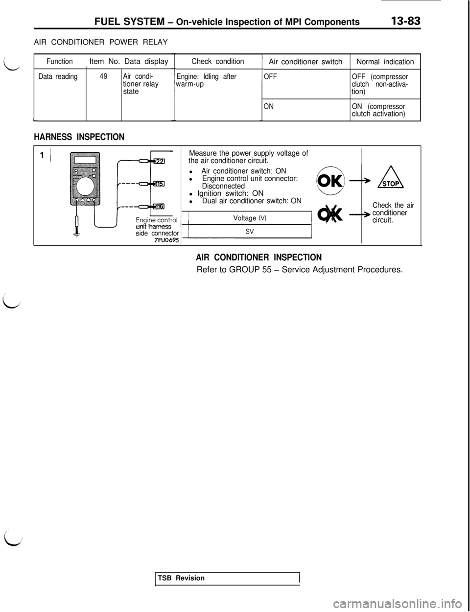
AIR CONDITIONER POWER RELAY
L
FunctionItem No. Data display
Data reading49Air condi-tioner relay
stateCheck conditionEngine: Idling after
warm-up
HARNESS INSPECTIONAir conditioner switch
Normal indication
OFFOFF (compressor
clutch non-activa-
tion)
ONON (compressorclutch activation)
’ I
unit harness
side connector
7FUO695
Measure the power supply voltage of
the air conditioner circuit.l
Air conditioner switch: ONlEngine control unit connector:
Disconnectedl Ignition switch: ON
l
Dual air conditioner switch: ONVoltage
(V)IM
ASTOP
Check the airconditioner
circuit.
AIR CONDITIONER INSPECTIONRefer to GROUP 55
- Service Adjustment Procedures.
TSB Revision
Page 190 of 1146
13-84FUEL SYSTEM - 0n-vehicle Inspection of MPI Components
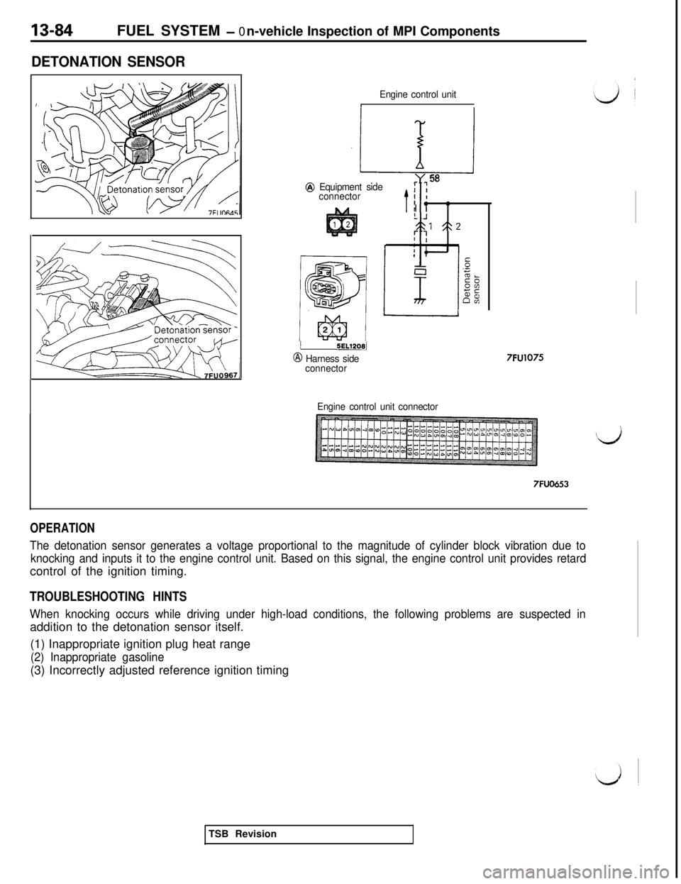
DETONATION SENSOR
Engine control unitN
/J-l
@ Equipment side58: :connectorI I
t- =I IL .J531 5:2::
i SEL1208j
@ Harness side
connector7FU1075
Engine control unit connector
7FUO653
OPERATION
The detonation sensor generates a voltage proportional to the magnitude of cylinder block vibration due to
knocking and inputs it to the engine control unit. Based on this signal, the engine control unit provides retardcontrol of the ignition timing.
TROUBLESHOOTING HINTS
When knocking occurs while driving under high-load conditions, the following problems are suspected inaddition to the detonation sensor itself.
(1) Inappropriate ignition plug heat range
(2) Inappropriate gasoline(3) Incorrectly adjusted reference ignition timing
TSB Revision