differential MITSUBISHI 3000GT 1991 User Guide
[x] Cancel search | Manufacturer: MITSUBISHI, Model Year: 1991, Model line: 3000GT, Model: MITSUBISHI 3000GT 1991Pages: 1146, PDF Size: 76.68 MB
Page 386 of 1146

22-6MANUAL TRANSAXLE
LUBRICANTS
M22CD-A
Items
Manual transmission oil
Drive shaft oil seal lip
Specified lubricant
Hypoid gear oil, SAE
75W-90 or75W-85W conforming to APIclassification GL-4 or higherQuantity lit.
(qts)
2.3 (2.4)
As required
SEALANTS AND ADHESIVES
Items
Transaxle case - clutch housing mating surfaces
Transaxle case
- rear cover mating surfaces
Differential drive gear bolts
Bearing retainer screw (flush head screw)
Reverse brake cone mounting screw bolts
MUCE- _
Specified sealants and adhesives
Mitsubishi genuine part No. 997740 or equivalent
3M Stud Locking part No. 4170 or equivalent
Air breather
3M ATD part No. 8001 or equivalent
SPECIAL TOOLSM22DA-A.
nstallation of spring pin and lock
MD998323-01TSB Revision
Page 387 of 1146

MANUAL TRANSAXLE
MD998348-0 1
Bearing remover
Removal of gears and bearings of input
shaft, intermediate gear and output shaft
andintermediate shaft lock nut
M
D998808-01Snap ring installerInstallation of input shaft rear snap ring
MD998822installer adapterInstallation of differential case bearings
iTSB Revision
Page 401 of 1146

MANUAL TRANSAXLE
15-22Nm5211-15
ft.lbs..I 53
-22Nm
-15 ftlbs.
67
litI63
62
51.Screw52.Bolt53.Bearing retainer54. Intermediate gear assembly
55. Input shaft assembly
56. Output shaft assembly
57. Differential gear assembly
58. Bearing outer race
59. Bearing outer race60.Oil guide61. Bearing outer race
62. Bearing outer race
** 63. Oil seall 464.Oil seal65.Magnet66.Magnet holder
67. Clutch housing assembly
TSB Revision
Page 405 of 1146
MANUAL TRANSAXLE
22-25
L
Slit
#Jl
Spring pin
/
II-+Shift rail1 I I201034
er
2150008
MD998325-01
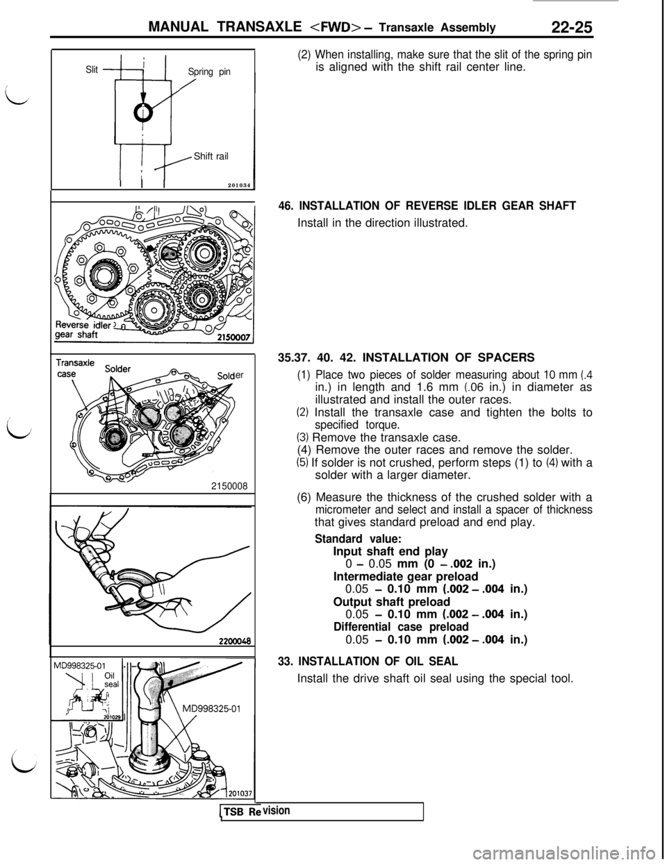
(2) When installing, make sure that the slit of the spring pinis aligned with the shift rail center line.
46. INSTALLATION OF REVERSE IDLER GEAR SHAFTInstall in the direction illustrated.
35.37. 40. 42. INSTALLATION OF SPACERS
(1) Place two pieces of solder measuring about 10 mm (.4in.) in length and 1.6 mm
(.06 in.) in diameter as
illustrated and install the outer races.
(2) Install the transaxle case and tighten the bolts to
specified torque.
(3) Remove the transaxle case.
(4) Remove the outer races and remove the solder.
(5) If solder is not crushed, perform steps (1) to (4) with a
solder with a larger diameter.
(6) Measure the thickness of the crushed solder with a
micrometer and select and install a spacer of thicknessthat gives standard preload and end play.
Standard value:Input shaft end play
0
- 0.05 mm (0 - .002 in.)
Intermediate gear preload
0.05
- 0.10 mm (.002 - .004 in.)
Output shaft preload
0.05
- 0.10 mm (.002 - .004 in.)
Differential case preload0.05
- 0.10 mm (.002 - .004 in.)
33. INSTALLATION OF OIL SEALInstall the drive shaft oil seal using the special tool.
visionI
Page 406 of 1146
22-26MANUAL TRANSAXLE .
Amountl-2 mm
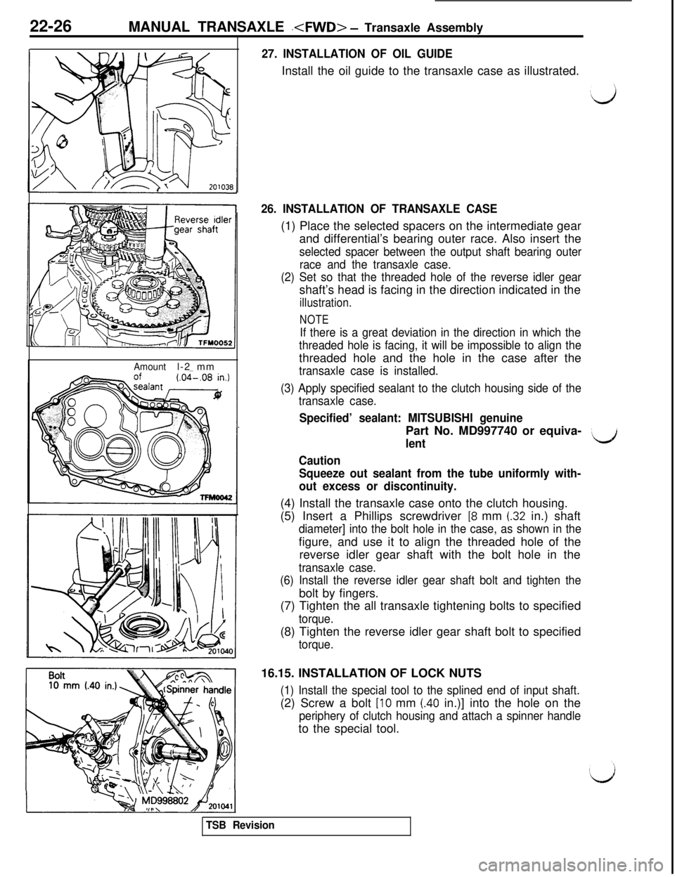
27. INSTALLATION OF OIL GUIDEInstall the oil guide to the transaxle case as illustrated.
26. INSTALLATION OF TRANSAXLE CASE(1) Place the selected spacers on the intermediate gear
and differential’s bearing outer race. Also insert the
selected spacer between the output shaft bearing outer
race and the transaxle case.
(2) Set so that the threaded hole of the reverse idler gearshaft’s head is facing in the direction indicated in the
illustration.
NOTE
If there is a great deviation in the direction in which the
threaded hole is facing, it will be impossible to align thethreaded hole and the hole in the case after the
transaxle case is installed.
(3) Apply specified sealant to the clutch housing side of the
transaxle case.
Specified’ sealant: MITSUBISHI genuinePart No. MD997740 or equiva-
lentLJ
Caution
Squeeze out sealant from the tube uniformly with-
out excess or discontinuity.(4) Install the transaxle case onto the clutch housing.
(5) Insert a Phillips screwdriver
[8 mm (.32 in.) shaft
diameter] into the bolt hole in the case, as shown in thefigure, and use it to align the threaded hole of the
reverse idler gear shaft with the bolt hole in the
transaxle case.
(6) Install the reverse idler gear shaft bolt and tighten thebolt by fingers.
(7) Tighten the all transaxle tightening bolts to specified
torque.(8) Tighten the reverse idler gear shaft bolt to specified
torque.16.15. INSTALLATION OF LOCK NUTS
(1) Install the special tool to the splined end of input shaft.(2) Screw a bolt
[lo mm (.40 in.)] into the hole on the
periphery of clutch housing and attach a spinner handleto the special tool.
TSB Revision
Page 423 of 1146
MANUAL TRANSAXLE
DIFFERENTIAL ASSEMBLY
IDISASSEMBLY AND REASSEMBLY
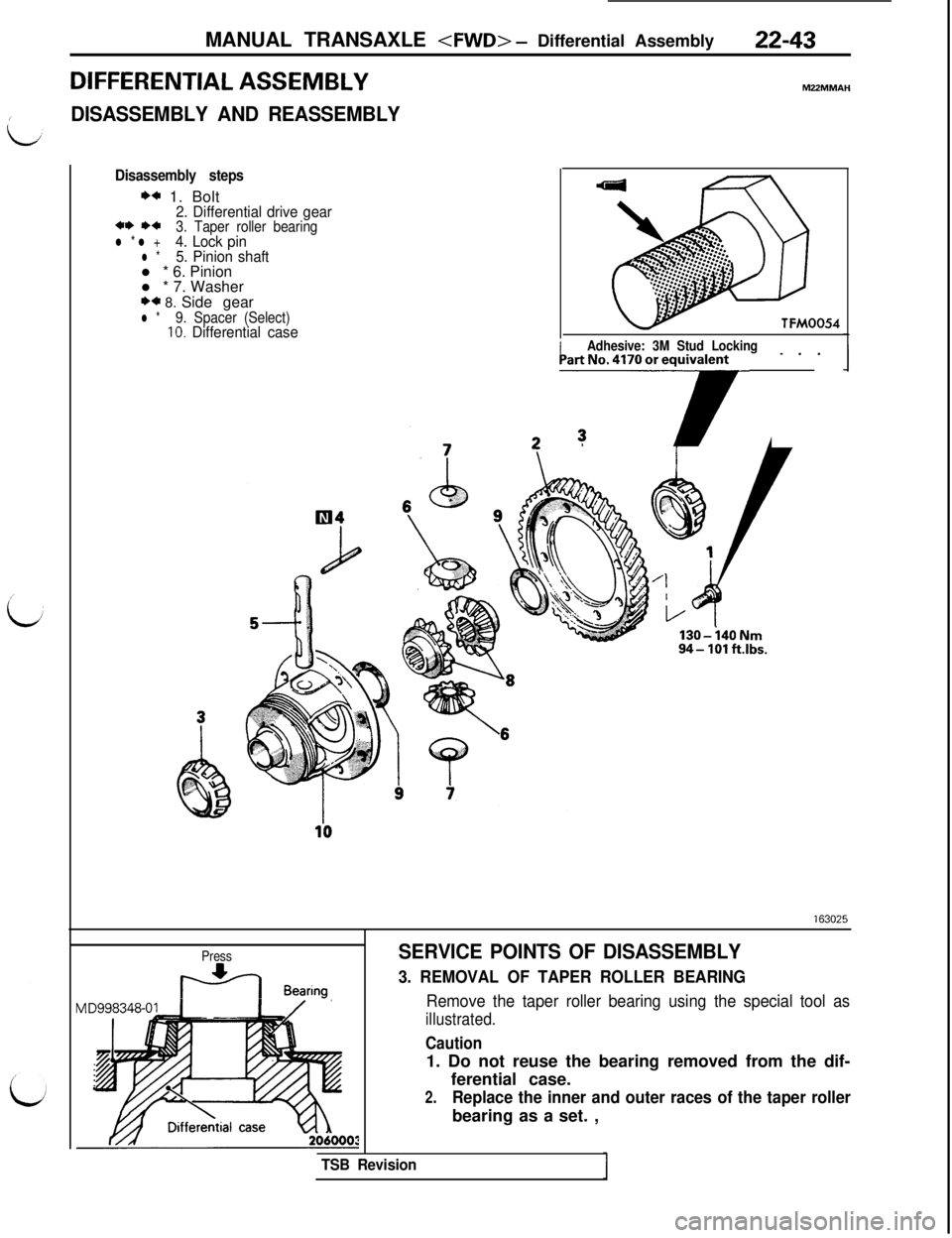
Disassembly steps
** 1. Bolt2. Differential drive gear** *+3. Taper roller bearingl * l +4. Lock pinl *5. Pinion shaftl * 6. Pinion
l * 7. Washer
** 8. Side gearl *9. Spacer (Select)10. Differential caseTFM0054
/Adhesive: 3M Stud Locking- . .] _PartNo.417Ooreqr
130-i40Nnl94- 101 ft.lbs.
Press
ti Bearmg
SERVICE POINTS OF DISASSEMBLY
3. REMOVAL OF TAPER ROLLER BEARING
Remove the taper roller bearing using the special tool as
illustrated.
Caution1. Do not reuse the bearing removed from the dif-
ferential case.
2.Replace the inner and outer races of the taper rollerbearing as a set. ,
TSB Revision
Page 424 of 1146
22-44MANUAL TRANSAXLE
Lock pin
Pinion shaft
2 150020160124
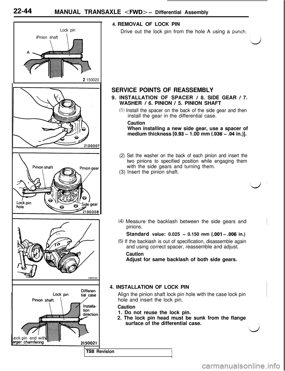
Differen-ock pinend with4. REMOVAL OF LOCK PIN
Drive out the lock pin from the hole A using a
punch.
:,,)
SERVICE POINTS OF REASSEMBLY9. INSTALLATION OF SPACER
/ 8. SIDE GEAR / 7.
WASHER
/ 6. PINION / 5. PINION SHAFT
(I 1 Install the spacer on the back of the side gear and theninstall the gear in the differential case.
CautionWhen installing a new side gear, use a spacer of
medium thickness
[0.93 - 1.00 mm (.036 - .04 in.)].
(2) Set the washer on the back of each pinion and insert the
two pinions to specified position while engaging themwith the side gears and turning them.
(3) Insert the pinion shaft.
(4) Measure the backlash between the side gears and
pinions.Standard value: 0.025
- 0.150 mm (.OOl - .006 in.)
(5) If the backlash is out of specification, disassemble againand using correct spacer, reassemble and adjust.
CautionAdjust for same backlash of both side gears.
4. INSTALLATION OF LOCK PIN
Align the pinion shaft lock pin hole with the case lock pin
hole and insert the lock pin.
Caution1. Do not reuse the lock pin.
2. The lock pin head must be sunk from the flange
surface of the differential case.
TSB Revision1
Page 425 of 1146
MANUAL TRANSAXLE
- ometer Driven Gear Assembly22-45
TFYOO4Q
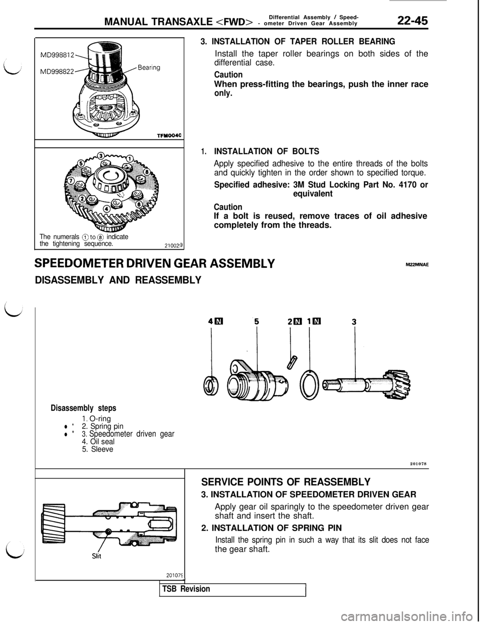
The numerals @to @ indicate
the tightening sequence.
9
SPEEDOMETER DRIVEN GEAR ASSEMBLY
DISASSEMBLY AND REASSEMBLY
3. INSTALLATION OF TAPER ROLLER BEARINGInstall the taper roller bearings on both sides of the
differential case.
CautionWhen press-fitting the bearings, push the inner race
only.
1.INSTALLATION OF BOLTS
Apply specified adhesive to the entire threads of the bolts
and quickly tighten in the order shown to specified torque.
Specified adhesive: 3M Stud Locking Part No. 4170 or
equivalent
CautionIf a bolt is reused, remove traces of oil adhesive
completely from the threads.MZ2MNAE
Disassembly steps
I. O-ringl *2. Spring pin
l *3. Speedometer driven gear4. Oil seal
5. Sleeve201078
201075
SERVICE POINTS OF REASSEMBLY3. INSTALLATION OF SPEEDOMETER DRIVEN GEAR
Apply gear oil sparingly to the speedometer driven gear
shaft and insert the shaft.
2. INSTALLATION OF SPRING PIN
Install the spring pin in such a way that its slit does not facethe gear shaft.
J
TSB RevisionI
Page 428 of 1146
22-48MANUAL TRANSAXLE
MANUAL TRANSAXLE
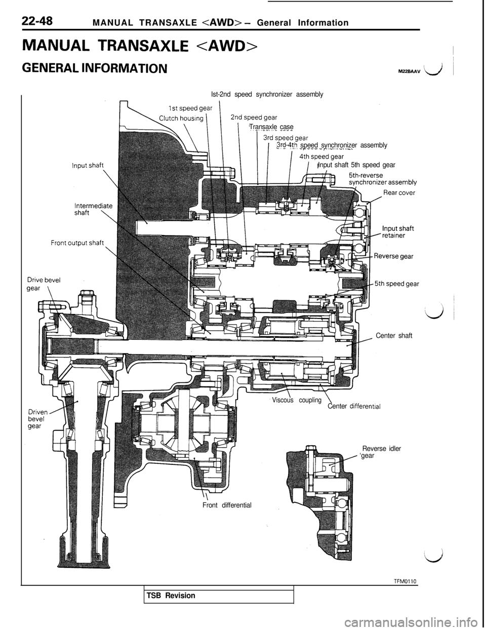
GENERAL INFORMATION~M22BAAV I\,i ~
Ist-2nd speed synchronizer assembly
Transaxle case
3rd-4th speed synchronizer assembly
Input shaft 5th speed gear
Center shaft
\Front differential
Viscous couplingCenter differentral
Reverse idler
‘gear
TFMOllO
TSB Revision
Page 429 of 1146
MANUAL TRANSAXLE
SPECIFICATIONS
22-49
MZZCA-B
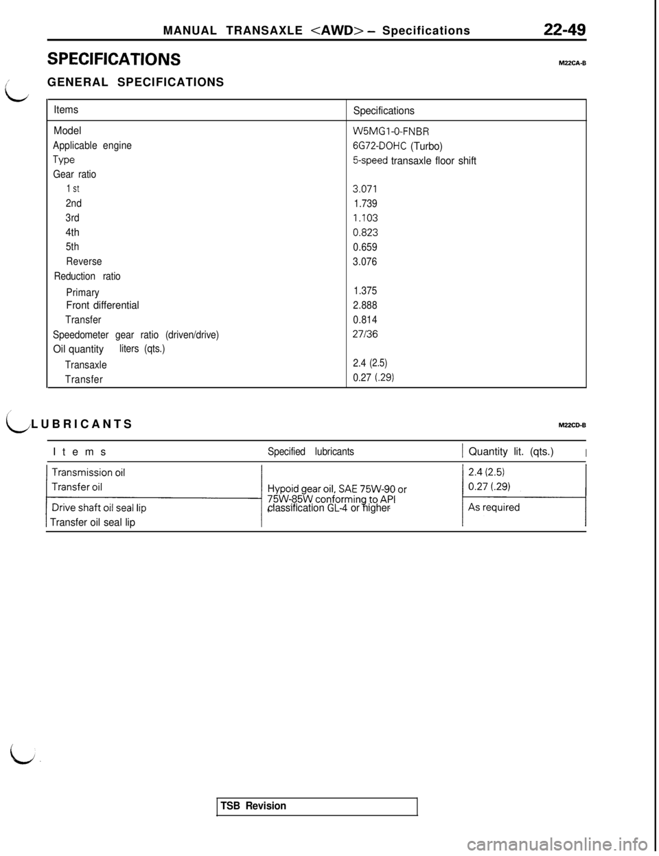
iGENERAL SPECIFICATIONS
L
Items
Model
Applicable engine
Type
Gear ratio
1 St
2nd
3rd
4th
5th
Reverse
Reduction ratio
Primary
Front differential
Transfer
Speedometer gear ratio (driven/drive)
Oil quantityliters (qts.)
Transaxle
Transfer
Specifications
W5MGl-0-FNBR
6G72-DOHC (Turbo)
5-speed transaxle floor shift
3.071
1.739
1.103
0.823
0.659
3.076
1.375
2.888
0.814
27136
2.4(2.5)
0.27(.29)
LLUBRICANTSMUCD-B
Items
Specified lubricants1 Quantity lit. (qts.)I
classification GL4 or higher
1 Transfer oil seal lip
a:
TSB Revision