MITSUBISHI 3000GT 1991 Service Manual
3000GT 1991
MITSUBISHI
MITSUBISHI
https://www.carmanualsonline.info/img/19/57085/w960_57085-0.png
MITSUBISHI 3000GT 1991 Service Manual
Trending: wheel, Drive belt, clutch, oil temperature, load capacity, recommended oil, engine oil
Page 421 of 1146
MANUAL TRANSAXLE - Output Shaft.Assembly22-41
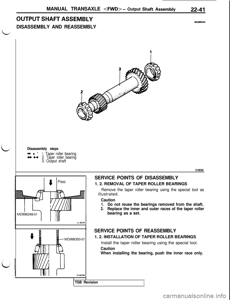
OUTPUT SHAFT ASSEMBLYMZZMKAH
DISASSEMBLY AND REASSEMBLY
L
/
id
I I
SERVICE POINTS OF DISASSEMBLY
8Press1. 2. REMOVAL OF TAPER ROLLER BEARINGS
Remove the taper roller bearing using the special tool asillustrated.
Caution
1.Do not reuse the bearings removed from the shaft.
2.Replace the inner and outer races of the taper rollerbearing as a set.
Disassembly steps**
l *I. Taper roller bearing*I) I)*2. Taper roller bearing3. Output shaft
210028
71 nn75
MD998350-01
SERVICE POINTS OF REASSEMBLY1. 2. INSTALLATION OF TAPER ROLLER BEARINGS
Install the taper roller bearing using the special tool.
Caution
When installing the bearing, push the inner race only.
TSB Revision1
Page 422 of 1146
22-42MANUAL TRANSAXLE - Shift Rails and Forks
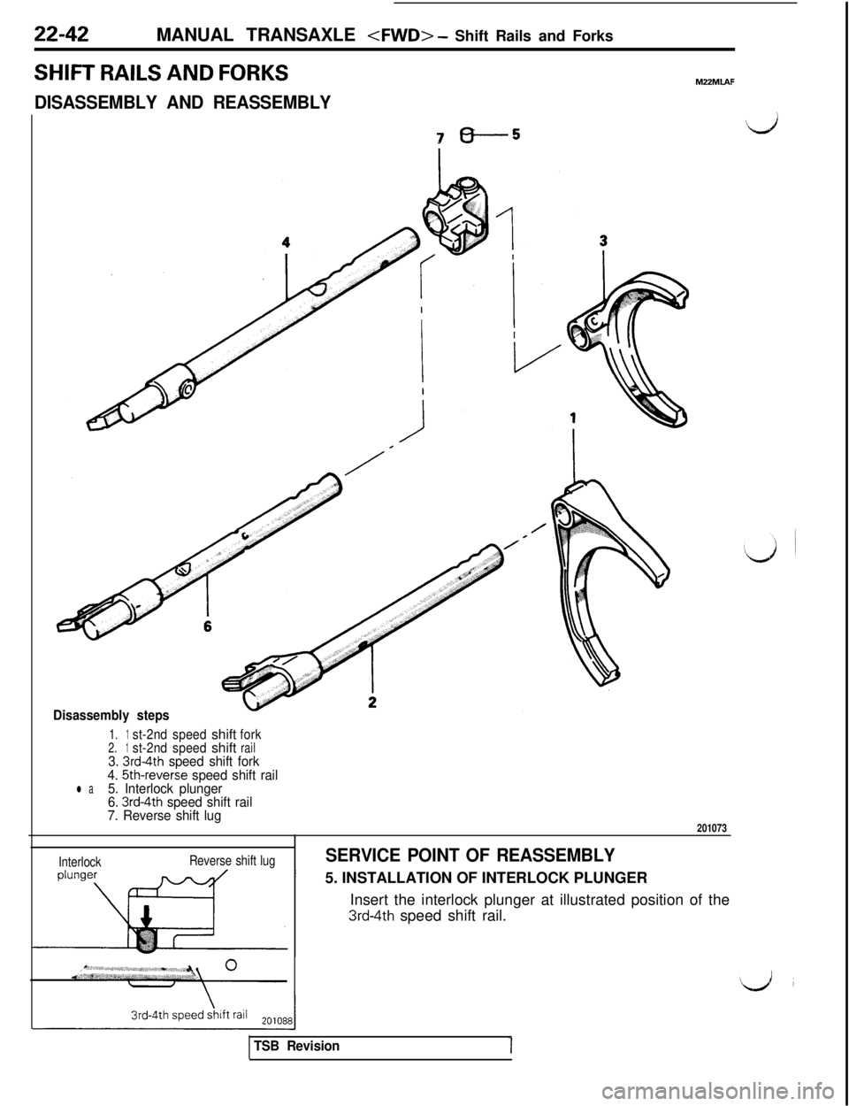
SHIFT RAILS AND FORKSMZZMLAF
DISASSEMBLY AND REASSEMBLY
7-5i-s
Disassembly steps
1.1st-2ndspeedshiftfork2.1st-2ndspeedshiftrail3. 3rd4th speed shift fork
4. 5th-reverse speed shift raill a5. Interlock plunger
6. 3rd-4th speed shift rail
7. Reverse shift lug
201073
InterlockReverse shift lugSERVICE POINT OF REASSEMBLY5. INSTALLATION OF INTERLOCK PLUNGER
Insert the interlock plunger at illustrated position of the
3rd-4th speed shift rail.
TSB Revision
Page 423 of 1146
MANUAL TRANSAXLE - Differential Assembly22-43
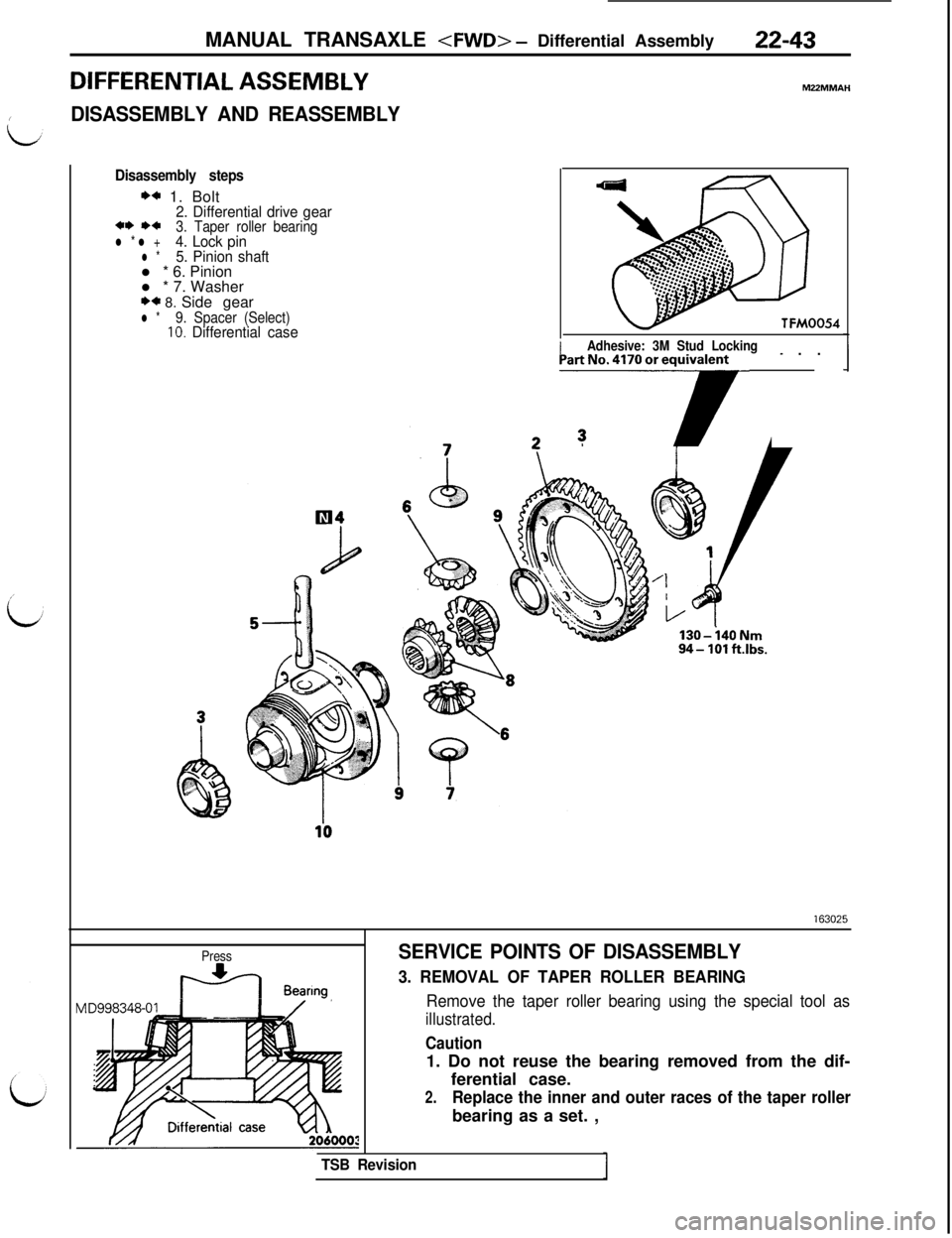
DIFFERENTIAL ASSEMBLY
IDISASSEMBLY AND REASSEMBLY
Disassembly steps
** 1. Bolt2. Differential drive gear** *+3. Taper roller bearingl * l +4. Lock pinl *5. Pinion shaftl * 6. Pinion
l * 7. Washer
** 8. Side gearl *9. Spacer (Select)10. Differential caseTFM0054
/Adhesive: 3M Stud Locking- . .] _PartNo.417Ooreqr
130-i40Nnl94- 101 ft.lbs.
Press
ti Bearmg
SERVICE POINTS OF DISASSEMBLY
3. REMOVAL OF TAPER ROLLER BEARING
Remove the taper roller bearing using the special tool as
illustrated.
Caution1. Do not reuse the bearing removed from the dif-
ferential case.
2.Replace the inner and outer races of the taper rollerbearing as a set. ,
TSB Revision
Page 424 of 1146
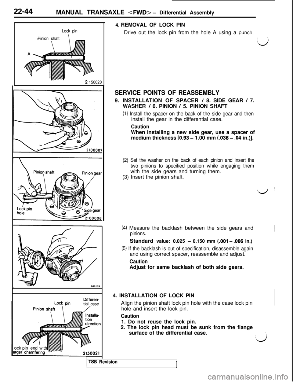
22-44MANUAL TRANSAXLE - Differential Assembly
Lock pin
Pinion shaft
2 150020160124
Differen-ock pinend with4. REMOVAL OF LOCK PIN
Drive out the lock pin from the hole A using a
punch.
:,,)
SERVICE POINTS OF REASSEMBLY9. INSTALLATION OF SPACER
/ 8. SIDE GEAR / 7.
WASHER
/ 6. PINION / 5. PINION SHAFT
(I 1 Install the spacer on the back of the side gear and theninstall the gear in the differential case.
CautionWhen installing a new side gear, use a spacer of
medium thickness
[0.93 - 1.00 mm (.036 - .04 in.)].
(2) Set the washer on the back of each pinion and insert the
two pinions to specified position while engaging themwith the side gears and turning them.
(3) Insert the pinion shaft.
(4) Measure the backlash between the side gears and
pinions.Standard value: 0.025
- 0.150 mm (.OOl - .006 in.)
(5) If the backlash is out of specification, disassemble againand using correct spacer, reassemble and adjust.
CautionAdjust for same backlash of both side gears.
4. INSTALLATION OF LOCK PIN
Align the pinion shaft lock pin hole with the case lock pin
hole and insert the lock pin.
Caution1. Do not reuse the lock pin.
2. The lock pin head must be sunk from the flange
surface of the differential case.
TSB Revision1
Page 425 of 1146
MANUAL TRANSAXLE Differential Assembly / Speed-
- ometer Driven Gear Assembly22-45
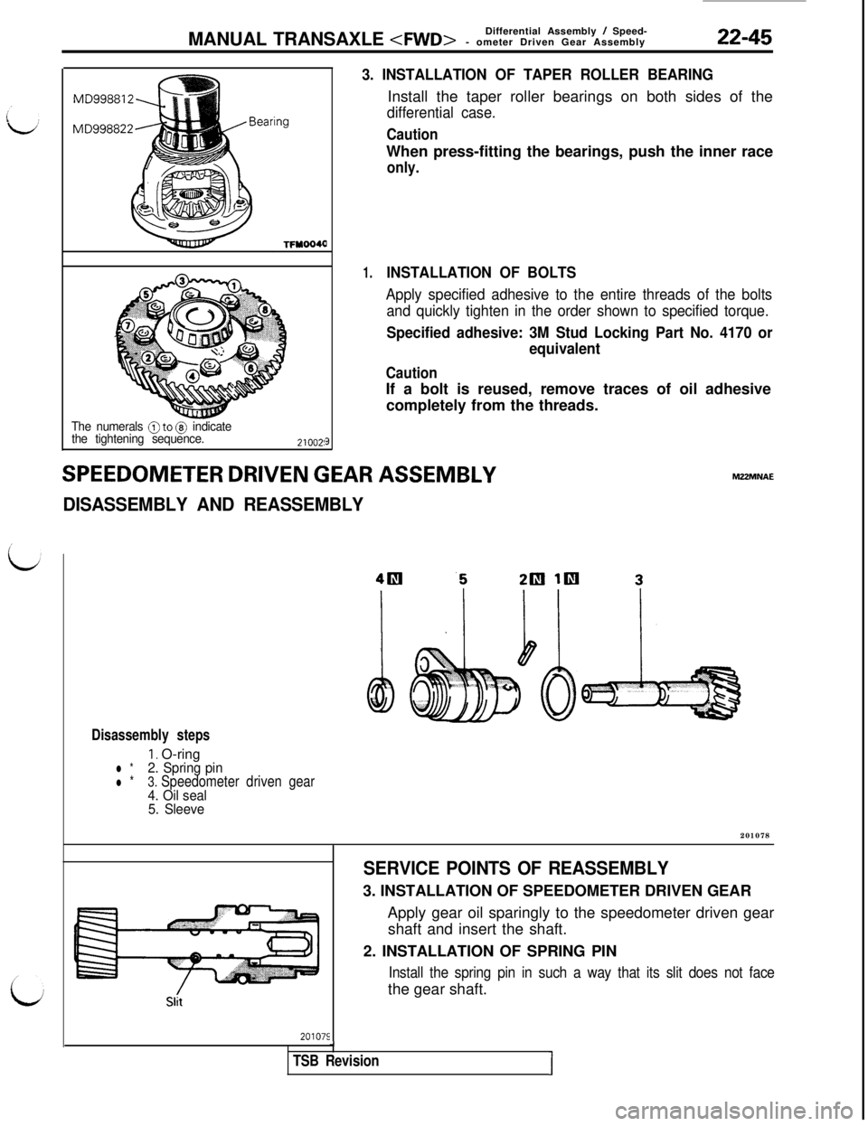
TFYOO4Q
The numerals @to @ indicate
the tightening sequence.
9
SPEEDOMETER DRIVEN GEAR ASSEMBLY
DISASSEMBLY AND REASSEMBLY
3. INSTALLATION OF TAPER ROLLER BEARINGInstall the taper roller bearings on both sides of the
differential case.
CautionWhen press-fitting the bearings, push the inner race
only.
1.INSTALLATION OF BOLTS
Apply specified adhesive to the entire threads of the bolts
and quickly tighten in the order shown to specified torque.
Specified adhesive: 3M Stud Locking Part No. 4170 or
equivalent
CautionIf a bolt is reused, remove traces of oil adhesive
completely from the threads.MZ2MNAE
Disassembly steps
I. O-ringl *2. Spring pin
l *3. Speedometer driven gear4. Oil seal
5. Sleeve201078
201075
SERVICE POINTS OF REASSEMBLY3. INSTALLATION OF SPEEDOMETER DRIVEN GEAR
Apply gear oil sparingly to the speedometer driven gear
shaft and insert the shaft.
2. INSTALLATION OF SPRING PIN
Install the spring pin in such a way that its slit does not facethe gear shaft.
J
TSB RevisionI
Page 426 of 1146
22-46MANUAL TRANSAXLE - Clutch Housing Assembly
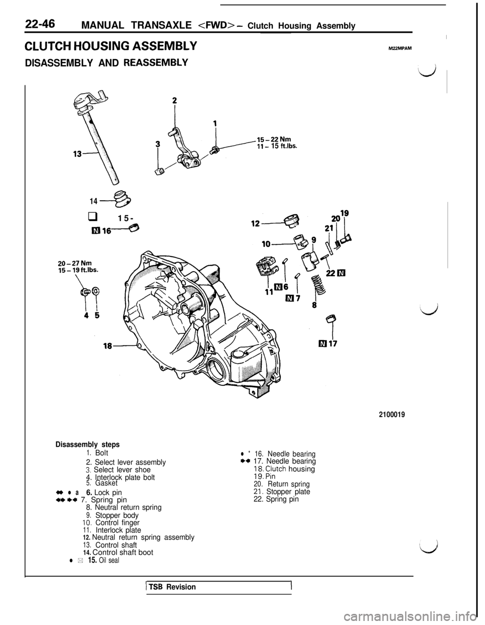
CLUTCH HOUSING ASSEMBLYM22MPAM
DISASSEMBLY AND REASSEMELY
iJ15-22Nm
II- 15 ft.lbs.
/
1443q 15-
m16----@20-27Nm
15- 19ft.lbs.
2100019
Disassembly steps
1.Bolt
2. Select lever assembly
3. Select lever shoe
4. Interlock plate bolt
5.Gasket
4~ l a6. Lock pin+* I)* 7. Spring pin8. Neutral return spring
9.Stopper body10.Control finger11.Interlock plate12. Neutral return spring assembly13.Control shaft14. Control shaft boot
l * 15. Oil seal
l *16.Needle
bearingI)+ 17. Needle bearing
; 98: F:;tch housing
20.Return
spring21. Stopper plate
22. Spring pin
1 TSB Revision1
Page 427 of 1146
MANUAL TRANSAXLE - Clutch Housing Assembly22-47
1
Oil sealSocketwrench
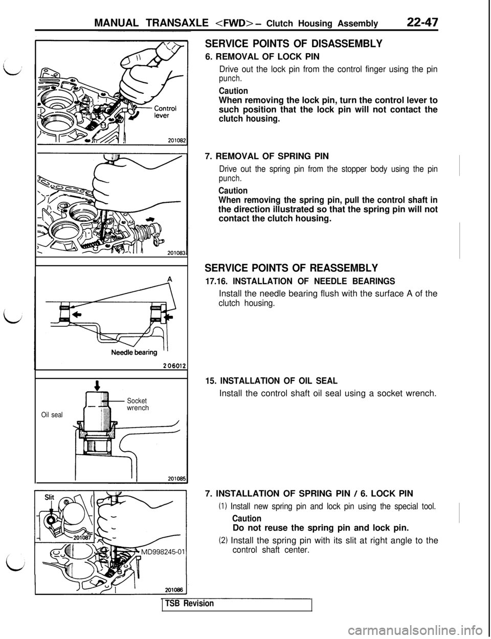
SERVICE POINTS OF DISASSEMBLY6. REMOVAL OF LOCK PIN
Drive out the lock pin from the control finger using the pin
punch.
CautionWhen removing the lock pin, turn the control lever to
such position that the lock pin will not contact the
clutch housing.7. REMOVAL OF SPRING PIN
Drive out the spring pin from the stopper body using the pin
punch.
Caution
When removing the spring pin, pull the control shaft inthe direction illustrated so that the spring pin will not
contact the clutch housing.
SERVICE POINTS OF REASSEMBLY
17.16. INSTALLATION OF NEEDLE BEARINGSInstall the needle bearing flush with the surface A of the
clutch housing.
15. INSTALLATION OF OIL SEALInstall the control shaft oil seal using a socket wrench.
7. INSTALLATION OF SPRING PIN
/ 6. LOCK PIN
(I) Install new spring pin and lock pin using the special tool.
CautionDo not reuse the spring pin and lock pin.
(2) Install the spring pin with its slit at right angle to the
control shaft center.
TSB Revision
Page 428 of 1146
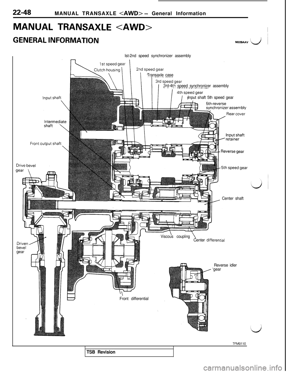
22-48MANUAL TRANSAXLE - General Information
MANUAL TRANSAXLE
GENERAL INFORMATION~M22BAAV I\,i ~
Ist-2nd speed synchronizer assembly
Transaxle case
3rd-4th speed synchronizer assembly
Input shaft 5th speed gear
Center shaft
\Front differential
Viscous couplingCenter differentral
Reverse idler
‘gear
TFMOllO
TSB Revision
Page 429 of 1146
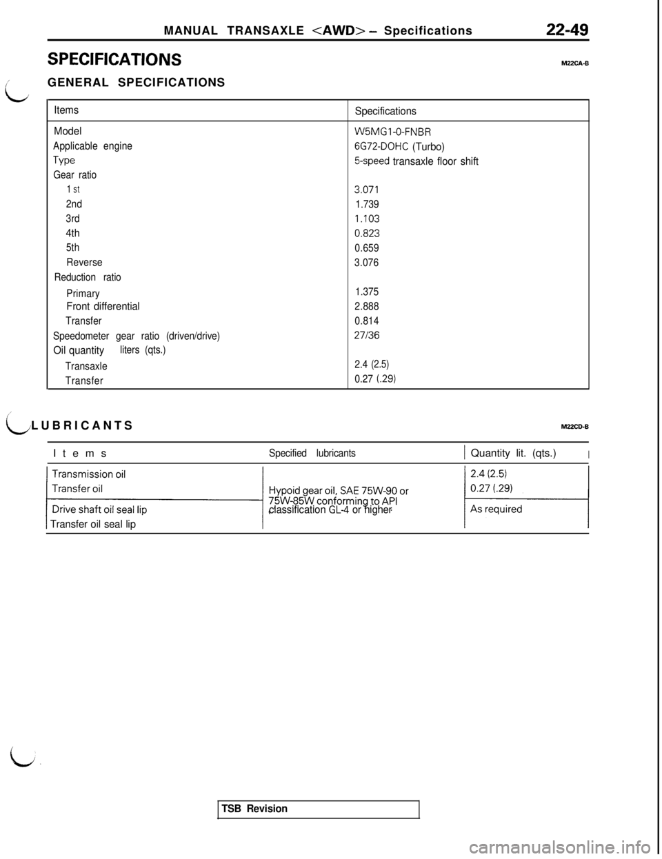
MANUAL TRANSAXLE - Specifications
SPECIFICATIONS
22-49
MZZCA-B
iGENERAL SPECIFICATIONS
L
Items
Model
Applicable engine
Type
Gear ratio
1 St
2nd
3rd
4th
5th
Reverse
Reduction ratio
Primary
Front differential
Transfer
Speedometer gear ratio (driven/drive)
Oil quantityliters (qts.)
Transaxle
Transfer
Specifications
W5MGl-0-FNBR
6G72-DOHC (Turbo)
5-speed transaxle floor shift
3.071
1.739
1.103
0.823
0.659
3.076
1.375
2.888
0.814
27136
2.4(2.5)
0.27(.29)
LLUBRICANTSMUCD-B
Items
Specified lubricants1 Quantity lit. (qts.)I
classification GL4 or higher
1 Transfer oil seal lip
a:
TSB Revision
Page 430 of 1146
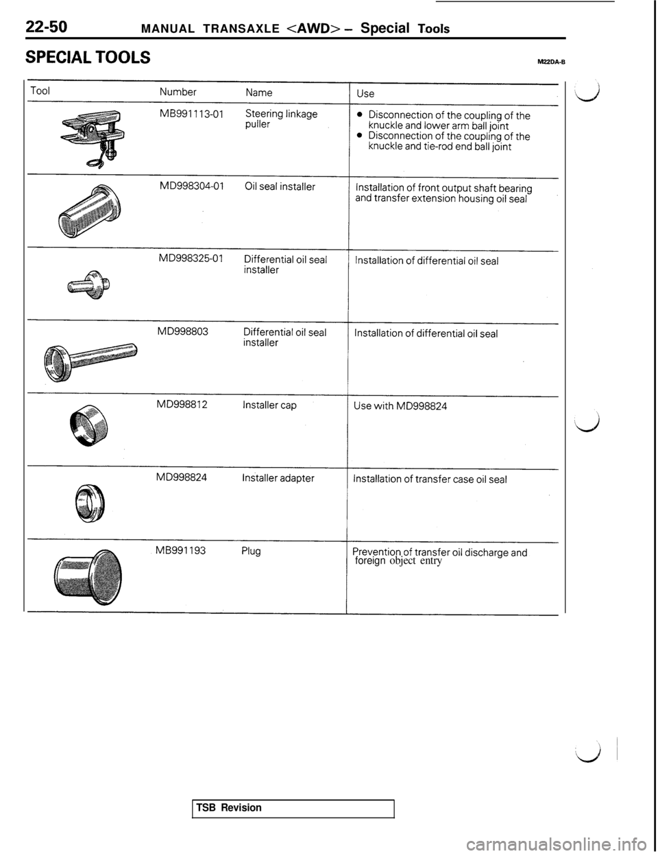
22-50MANUAL TRANSAXLE - Special T.ools
SPECIAL TOOLSMZZDA-B
foreign object entry
TSB Revision
Trending: fuel pressure, wheel bolts, gas type, suspension, dimensions, warning light, oil capacity
