MITSUBISHI 3000GT 1991 Service Manual
Manufacturer: MITSUBISHI, Model Year: 1991, Model line: 3000GT, Model: MITSUBISHI 3000GT 1991Pages: 1146, PDF Size: 76.68 MB
Page 391 of 1146
MANUAL TRANSAXLE
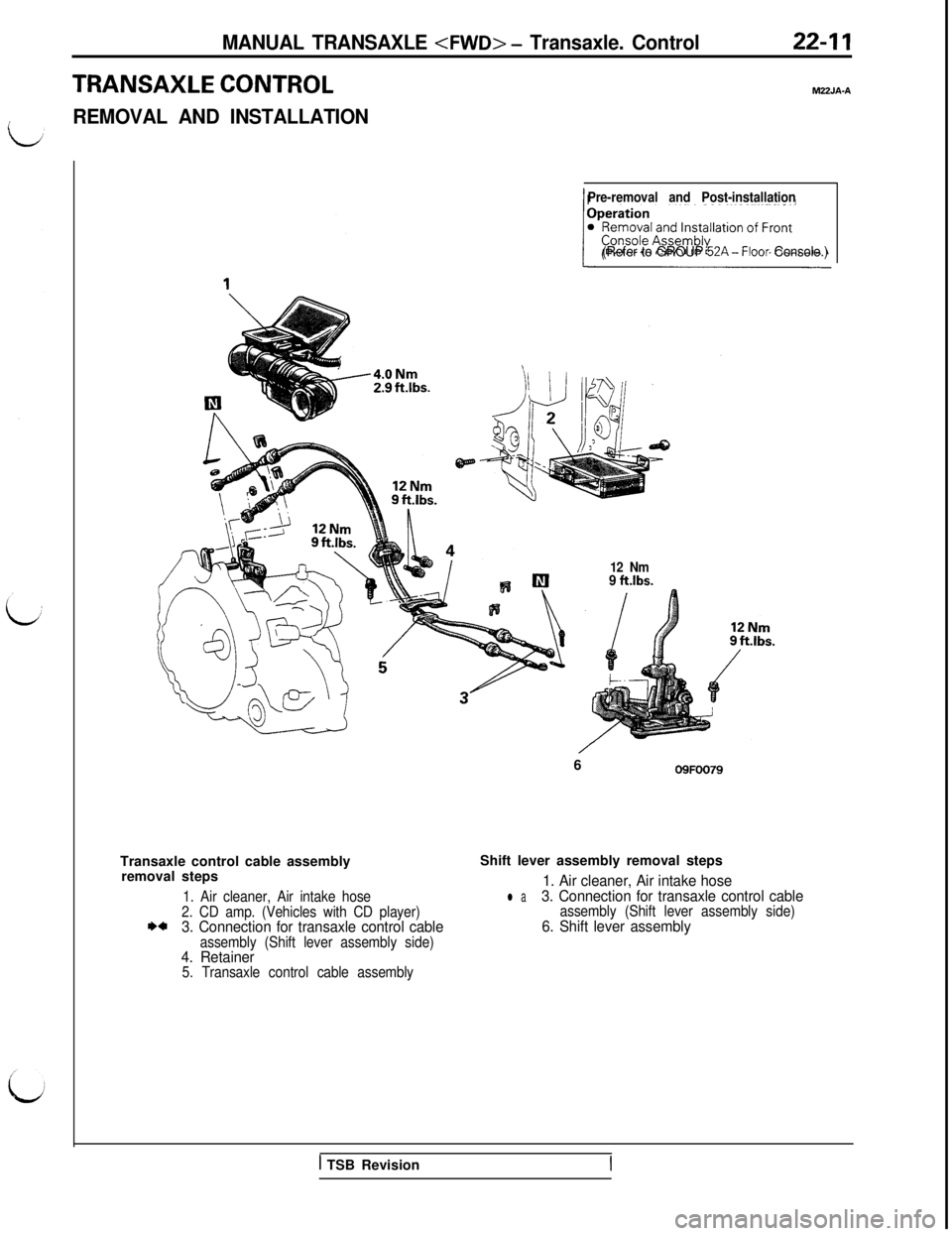
TRANSAXLE CONTROLM22JA-A
IREMOVAL AND INSTALLATION
Pre-removal and Post-installation
(Refer to GROUP 52A-Floor Console.)Transaxle control cable assembly
removal steps
1. Air cleaner, Air intake hose
2. CD amp. (Vehicles with CD player)
I)*3. Connection for transaxle control cableassembly (Shift lever assembly side)4. Retainer5. Transaxle control cable assembly12 Nm
9 ft.lbs.
/6
09FOO79Shift lever assembly removal steps
1. Air cleaner, Air intake hose
l a3. Connection for transaxle control cableassembly (Shift lever assembly side)6. Shift lever assembly
1 TSB Revision
Page 392 of 1146
22-12MANUAL TRANSAXLE
INSPECTIONM22JCAFl
lCheck the transaxle control cable assembly for function and
for damage.
l Check the boot for damage.
IlJ 1
lCheck each bushing for wear or abrasion, sticking, impeded
action, and damage.
0910023Lever B09FOO71
End of select cable
er B
Neutral position
OSFOOo8
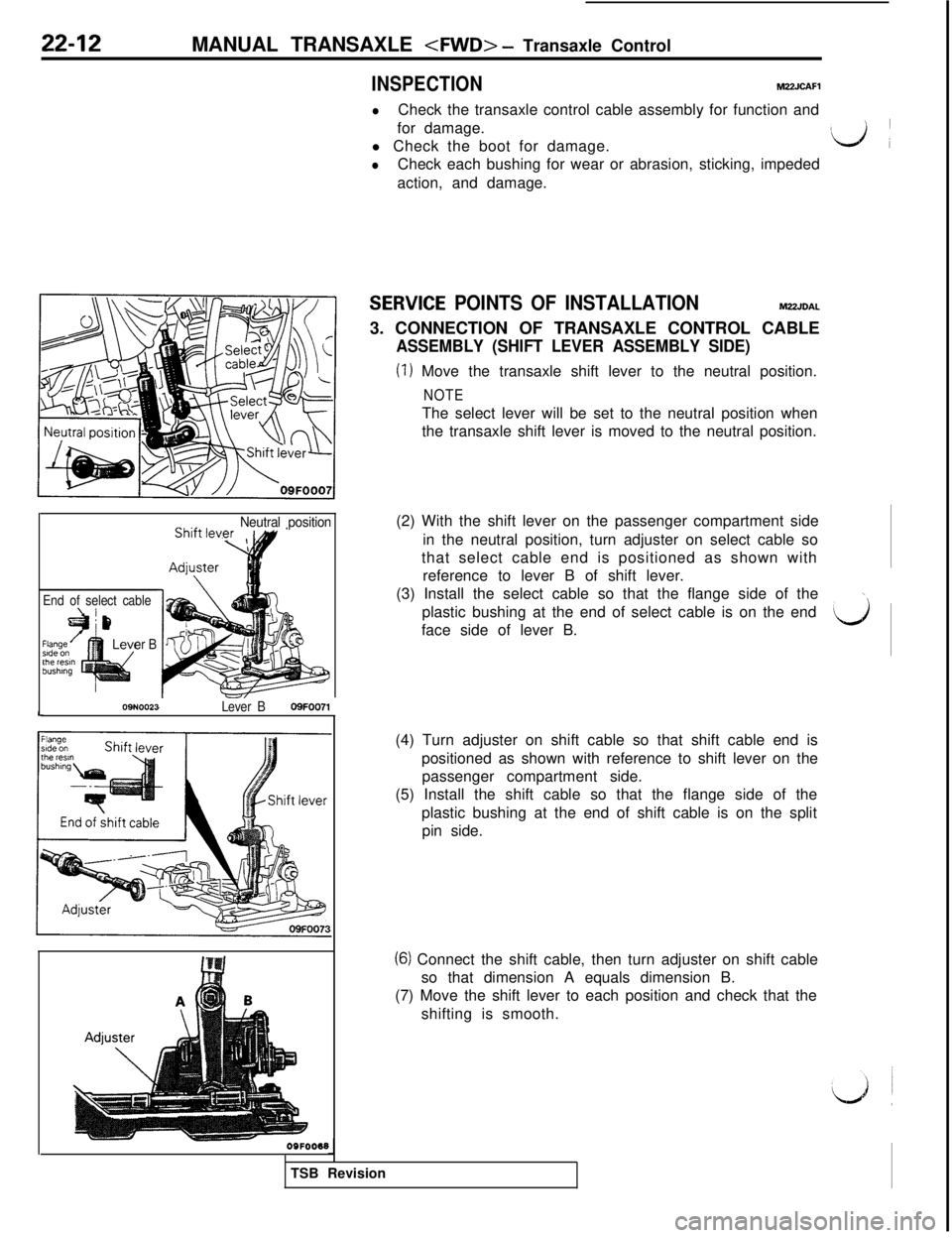
SERVlCE POINTS OF INSTALLATIONMUJDAL
3. CONNECTION OF TRANSAXLE CONTROL CABLE
ASSEMBLY (SHIFT LEVER ASSEMBLY SIDE)
(I) Move the transaxle shift lever to the neutral position.
NOTEThe select lever will be set to the neutral position when
the transaxle shift lever is moved to the neutral position.
(2) With the shift lever on the passenger compartment side
in the neutral position, turn adjuster on select cable so
that select cable end is positioned as shown with
reference to lever B of shift lever.
(3) Install the select cable so that the flange side of the
\plastic bushing at the end of select cable is on the end
face side of lever B.
d(4) Turn adjuster on shift cable so that shift cable end is
positioned as shown with reference to shift lever on the
passenger compartment side.
(5) Install the shift cable so that the flange side of the
plastic bushing at the end of shift cable is on the split
pin side.
(6) Connect the shift cable, then turn adjuster on shift cable
so that dimension A equals dimension B.
(7) Move the shift lever to each position and check that the
shifting is smooth.
TSB Revision
Page 393 of 1146
MANUAL TRANSAXLE
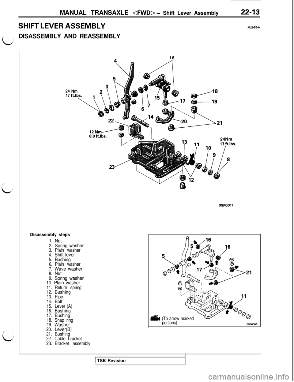
SHIFT LEVER ASSEMBLY
iDISASSEMBLY AND REASSEMBLY
2417Nmftlbs.
\Disassembly steps
1.Nut2.Spring washer3.Plain washer4.Shift lever5.Bushing6.Plain washer7.Wave washer8.Nut9.Spring washerIO. Plain washer11.Return spring12.Bushing13.Pipe14.Bolt15.Lever (A)16.Bushing17.Bushing18.Snap ring19.Washer20.Lever(B)21.Bushing22.Cable bracket
23.Bracket assembly16
24Nm
09FOO17
M22GE-A
(To arrow marked
portions)
OS%=0066
1 TSB Revision
Page 394 of 1146
22-14MANUAL TRANSAXLE
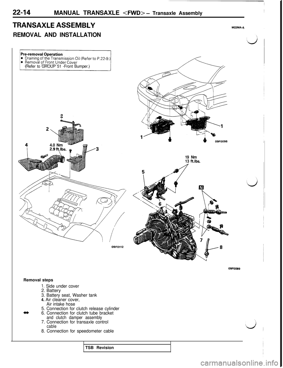
TRANSAXLE ASSEMBLY
REMOVAL AND INSTALLATION
(Refer to GROUP 51 -Front Bumper.)
4.0 Nm2.9ft$bs. t09FO112
19 Nm
13 ft.lbs.M22MA-A
Removal steps
1. Side under cover2. Battery
3. Battery seat, Washer tank
4. Air cleaner cover,
Air intake hose
5. Connection for clutch release cylinder
6. Connection for clutch tube bracket
and clutch damper assembly7. Connection for transaxle controlcable
8. Connection for speedometer cable09FOO89
TSB Revision
Page 395 of 1146
MANUAL TRANSAXLE
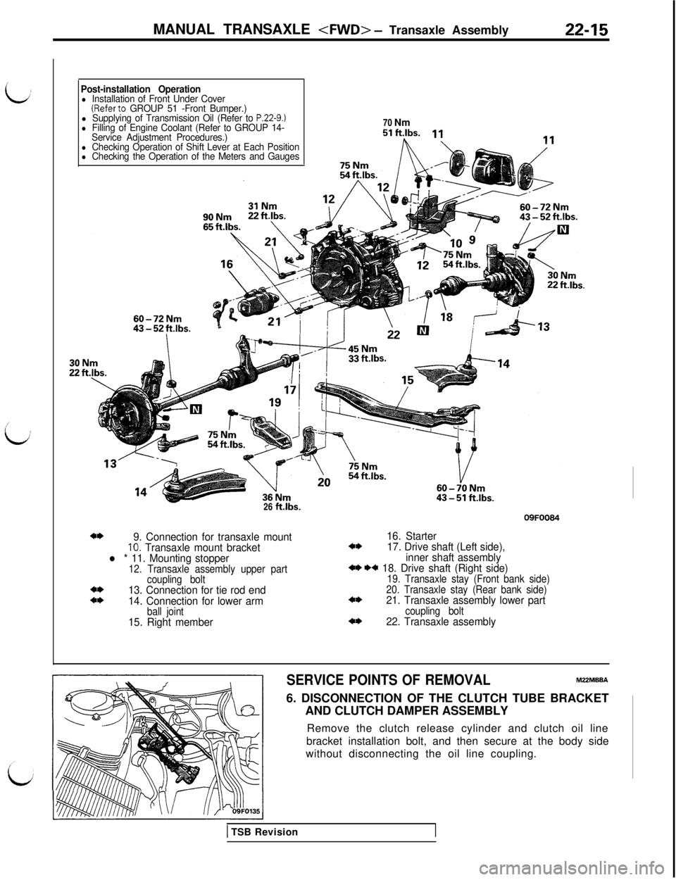
idPost-installation Operationl Installation of Front Under Cover(Referto GROUP 51 -Front Bumper.)l Supplying of Transmission Oil (Refer to P.22-9.)l Filling of Engine Coolant (Refer to GROUP 14-
Service Adjustment Procedures.)70 Nm
l Checking Operation of Shift Lever at Each Positionl Checking the Operation of the Meters and Gauges26
ft.lbs.09FOO84
4*9. Connection for transaxle mount16. Starter10. Transaxle mount bracket4*17. Drive shaft (Left side),
l * 11. Mounting stopperinner shaft assembly12. Transaxle assembly upper part+* ** 18. Drive shaft (Right side)
coupling bolt19. Transaxle stay (Front bank side)4*13. Connection for tie rod end20. Transaxle stay (Rear bank side)4*14. Connection for lower arm4*21. Transaxle assembly lower part
ball jointcoupling bolt15. Right member4*22. Transaxle assembly
SERVICE POINTS OF REMOVALMZZMBBA6. DISCONNECTION OF THE CLUTCH TUBE BRACKET
AND CLUTCH DAMPER ASSEMBLY
Remove the clutch release cylinder and clutch oil line
bracket installation bolt, and then secure at the body side
without disconnecting the oil line coupling.
1 TSB Revision
Page 396 of 1146
22-16MANUAL TRANSAXLE
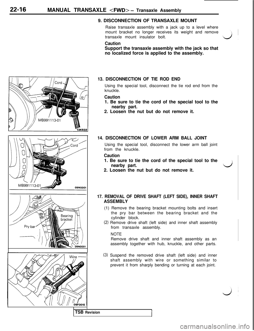
9. DISCONNECTION OF TRANSAXLE MOUNT
Raise transaxle assembly with a jack up to a level where
mount bracket no longer receives its weight and remove
transaxle mount insulator bolt.
CautionSupport the transaxle assembly with the jack so that
no localized force is applied to the assembly.
13. DISCONNECTION OF TIE ROD ENDUsing the special tool, disconnect the tie rod end from the
knuckle.
Caution1. Be sure to tie the cord of the special tool to the
nearby part.2. Loosen the nut but do not remove it.
14. DISCONNECTION OF LOWER ARM BALL JOINTUsing the special tool, disconnect the lower arm ball joint
from the knuckle.
Caution1. Be sure to tie the cord of the special tool to the
nearby part.2. Loosen the nut but do not remove it.
17. REMOVAL OF DRIVE SHAFT (LEFT SIDE), INNER SHAFT
ASSEMBLY(1) Remove the bearing bracket mounting bolts and insert
the pry bar between the bearing bracket and the
cylinder block.
(2) Remove drive shaft (left side) and inner shaft assembly
from transaxle assembly.
NOTERemove drive shaft and inner shaft assembly as an
assembly together with hub, knuckle, and other parts.
(3) Suspend the removed drive shaft (left side) and inner
shaft assembly with wire or something similar to
prevent it from sharply bending or turning at each joint.
TSB RevisionI
Page 397 of 1146
MANUAL TRANSAXLE
Transaxmount
bracket
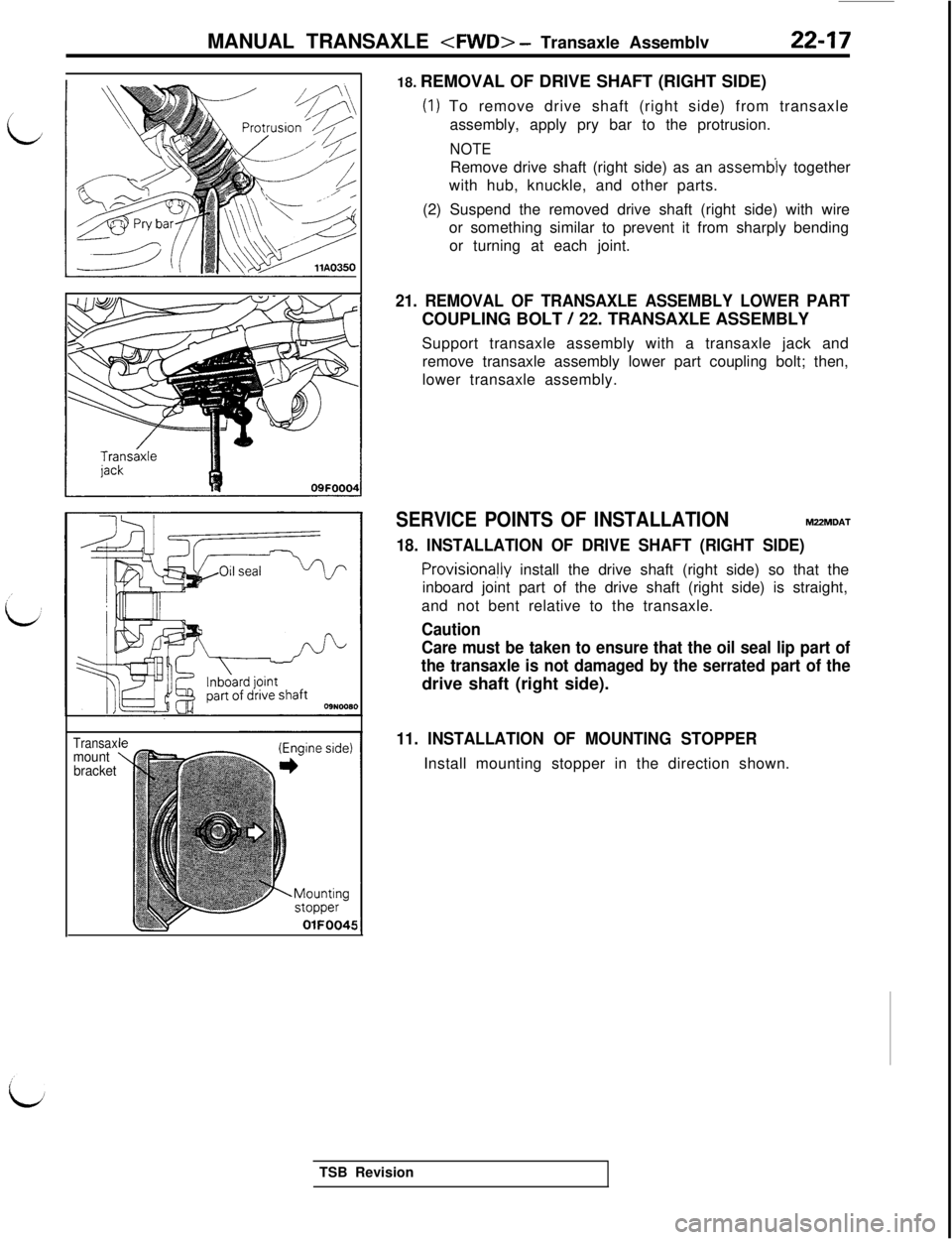
OlFOO4518. REMOVAL OF DRIVE SHAFT (RIGHT SIDE)
(1) To remove drive shaft (right side) from transaxle
assembly, apply pry bar to the protrusion.
NOTERemove drive shaft (right side) as an
assemb’ly together
with hub, knuckle, and other parts.
(2) Suspend the removed drive shaft (right side) with wire
or something similar to prevent it from sharply bending
or turning at each joint.
21. REMOVAL OF TRANSAXLE ASSEMBLY LOWER PARTCOUPLING BOLT
/ 22. TRANSAXLE ASSEMBLY
Support transaxle assembly with a transaxle jack and
remove transaxle assembly lower part coupling bolt; then,
lower transaxle assembly.
SERVICE POINTS OF INSTALLATIONM2ZMDAT
18. INSTALLATION OF DRIVE SHAFT (RIGHT SIDE)
ProvisionaHy install the drive shaft (right side) so that the
inboard joint part of the drive shaft (right side) is straight,
and not bent relative to the transaxle.
Caution
Care must be taken to ensure that the oil seal lip part of
the transaxle is not damaged by the serrated part of thedrive shaft (right side).
11. INSTALLATION OF MOUNTING STOPPERInstall mounting stopper in the direction shown.
TSB Revision
Page 398 of 1146
22-18MANUAL TRANSAXLE
TRANSAXLE ASSEMBLYIM22ME.A
I
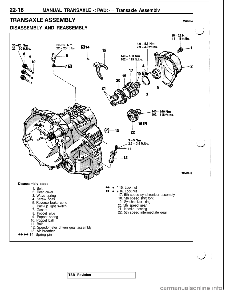
DISASSEMBLY AND REASSEMBLY
l5-22Nmdl
11 - 15 ftlbs.
-42 Nm
- 30 ftlbs.30-35 Nm
4.0 -5.5Nm
22
- 25 ft.lbs.lIll42.9 -3.9ftlbs.
/I18
J6140-160Nm1102-115ftlbs.
3-5Nm2.5 - 3.5 ftlbs.
11Disassembly steps
1.Bolt2.Rear cover3.Wave spring4.Screw bolts5. Reverse brake cone
6. Backup light switch
7.Gasket8.Poppet plug9.Poppet springIO. Poppet ball11.Bolt12. Speedometer driven gear assembly13.Air breather+* +* 14. Spring pin
*+ l * 15. Lock nut*+ l + 16. Lock nut17. 5th speed synchronizer assembly
18. 5th speed shift fork
19.Synchronizer ring20. 5th speed gear21.Needle bearing22. 5th speed intermediate gearTSB Revision
Page 399 of 1146
MANUAL TRANSAXLE
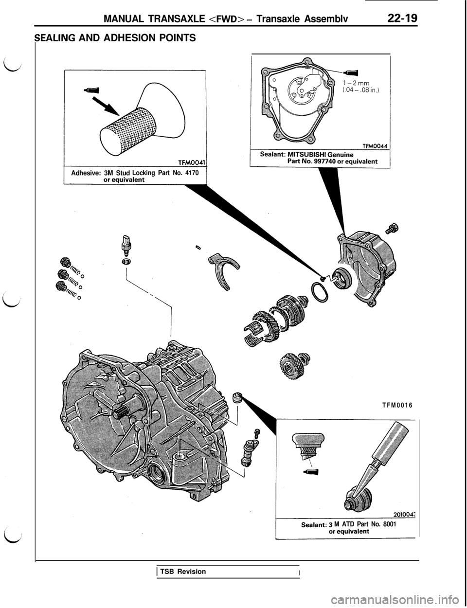
;EALING AND ADHESION POINTS
Adhesive: 3M StudLocking Part No. 4170TFM0016
M ATD Part No. 8001
1 TSB RevisionI
Page 400 of 1146
22-20MANUAL TRANSAXLE
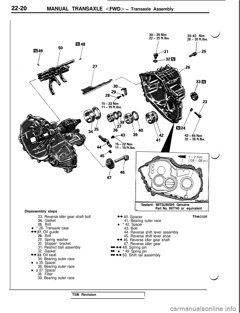
30-35Nm22 - 25ftlbs.35-42 Nm26 - 30ft.lbs.
43-55Nm32 - 39 ft.lbs.Disassembly steps
23. Reverse idler gear shaft bolt24.Gasket
25.Bolt
l * 26. Transaxle caseI)* 27. Oil guide28.Bolt29.Spring washer30.Stopper bracket31. Restrict ball assembly32.Gasket** 33. Oil seal34. Bearing outer racel a 35. Spacer36. Bearing outer racel a 37. Spacer38.Filter
39. Bearing outer raceSealant: MITSUBISHI Genuine
Part No. 997740 or equivalent
** 40. Spacer41. Bearing outer racel * 42. Spacer43. Bolt
44. Reverse shift lever assembly
45. Reverse shift lever shoe
** 46. Reverse idler gear shaft
47. Reverse idler gear
*I) I)+ 48. Spring pin*I) l * 49. Spring pin*,I) I)* 50. Shift rail assembly
TFMOlO9TSB Revision