MITSUBISHI 3000GT 1991 Service Manual
Manufacturer: MITSUBISHI, Model Year: 1991, Model line: 3000GT, Model: MITSUBISHI 3000GT 1991Pages: 1146, PDF Size: 76.68 MB
Page 851 of 1146
i
LSTEERING
- Power Steering Gear Box37A-23
13R054f
_ Needlebearing
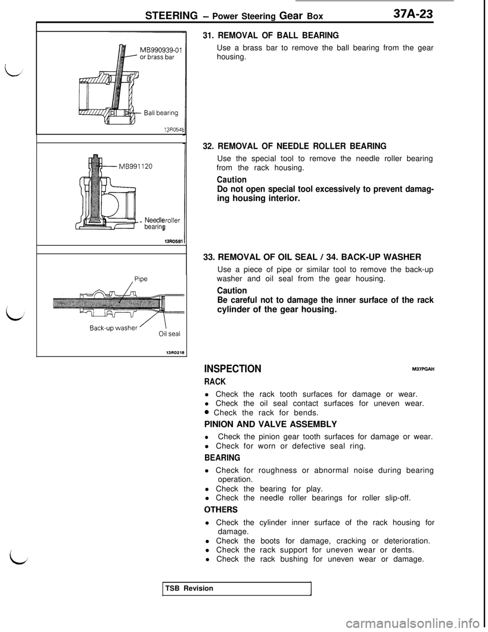
31. REMOVAL OF BALL BEARINGUse a brass bar to remove the ball bearing from the gear
housing.
32. REMOVAL OF NEEDLE ROLLER BEARINGUse the special tool to remove the needle roller bearing
from the rack housing.
Caution
Do not open special tool excessively to prevent damag-ing housing interior.
33. REMOVAL OF OIL SEAL
/ 34. BACK-UP WASHER
Use a piece of pipe or similar tool to remove the back-up
washer and oil seal from the gear housing.
Caution
Be careful not to damage the inner surface of the rackcylinder of the gear housing.
INSPECTION
RACK
M37PGAHl Check the rack tooth surfaces for damage or wear.
l Check the oil seal contact surfaces for uneven wear.
0 Check the rack for bends.
PINION AND VALVE ASSEMBLY
lCheck the pinion gear tooth surfaces for damage or wear.
l Check for worn or defective seal ring.
BEARINGl Check for roughness or abnormal noise during bearing
operation.
l Check the bearing for play.
l Check the needle roller bearings for roller slip-off.
OTHIERSl Check the cylinder inner surface of the rack housing for
damage.
l Check the boots for damage, cracking or deterioration.
l Check the rack support for uneven wear or dents.
l Check the rack bushing for uneven wear or damage.
TSB Revision
Page 852 of 1146
37A-24
STEERING - Power Steering Gear Box
/Oil seal
Back-up washer13A0181L
GuideNeedle roller
bearmg13R0547
MB990927-01
&
13R0378
Vent hole
SERVICE POINTS OF REASSEMBLYM37PHAW
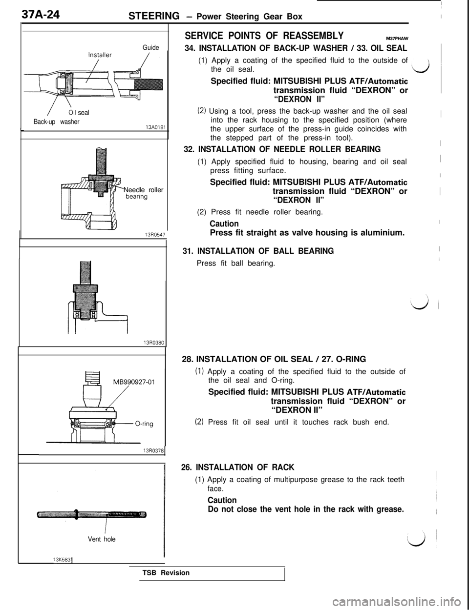
34. INSTALLATION OF BACK-UP WASHER / 33. OIL SEAL(1) Apply a coating of the specified fluid to the outside of
the oil seal.
LJSpecified fluid: MITSUBISHI PLUS
ATF/Automatictransmission fluid “DEXRON” or
“DEXRON II”
(2) Using a tool, press the back-up washer and the oil seal
into the rack housing to the specified position (whereIthe upper surface of the press-in guide coincides with
the stepped part of the press-in tool).
32. INSTALLATION OF NEEDLE ROLLER BEARINGI(1) Apply specified fluid to housing, bearing and oil seal
Ipress fitting surface.
ISpecified fluid: MITSUBISHI PLUS ATF/Automatictransmission fluid “DEXRON” or
I“DEXRON II”(2) Press fit needle roller bearing.
CautionIPress fit straight as valve housing is aluminium.
31. INSTALLATION OF BALL BEARINGPress fit ball bearing.
28. INSTALLATION OF OIL SEAL
/ 27. O-RING
(1) Apply a coating of the specified fluid to the outside of
the oil seal and O-ring.
Specified fluid: MITSUBISHI PLUS
ATF/Automatictransmission fluid “DEXRON” or
“DEXRON II”
(2) Press fit oil seal until it touches rack bush end.
26. INSTALLATION OF RACK(1) Apply a coating of multipurpose grease to the rack teeth
face.
Caution
Do not close the vent hole in the rack with grease.13K583(
TSB Revision
Page 853 of 1146
STEERING - Power Steering Gear Box37A-25
Back-up washer1360147
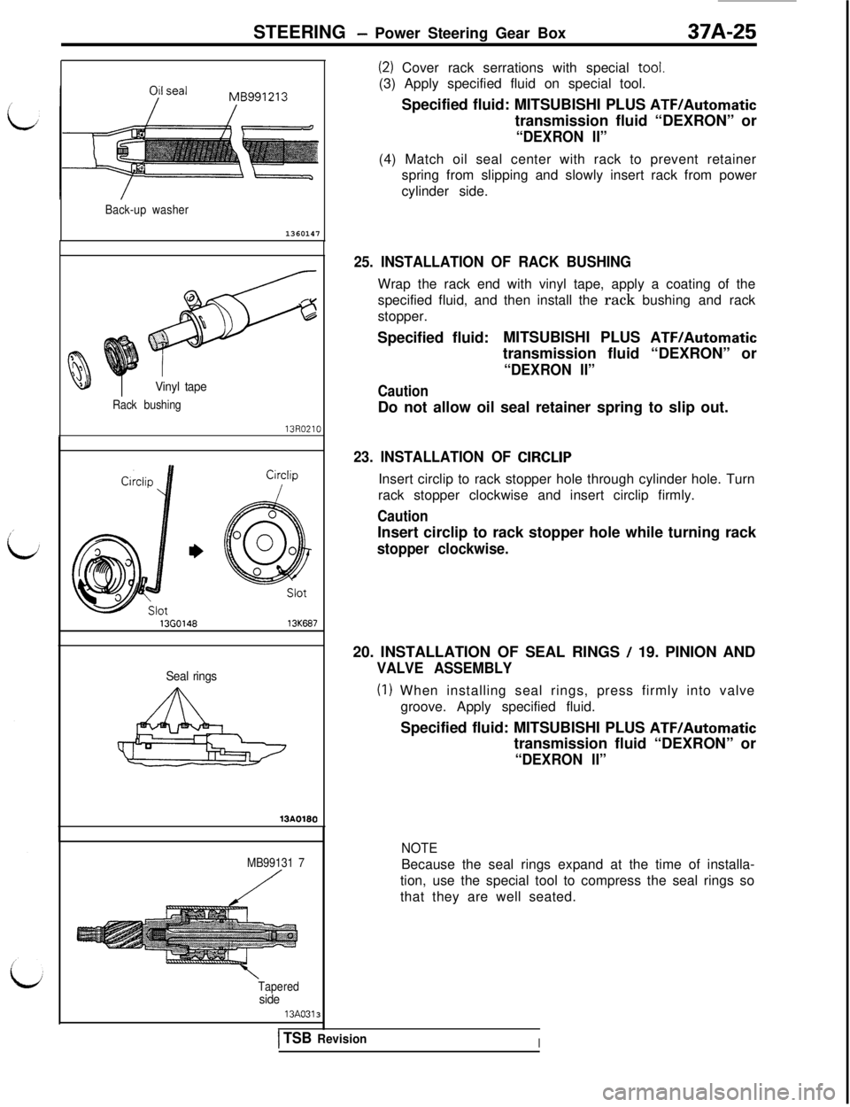
(2) Cover rack serrations with special tool.
(3) Apply specified fluid on special tool.
Specified fluid: MITSUBISHI PLUS
ATFIAutomatictransmission fluid “DEXRON” or
“DEXRON II”(4) Match oil seal center with rack to prevent retainer
spring from slipping and slowly insert rack from power
cylinder side.
Vinyl tape
Rack bushing
136014613K687
Seal rings
MB99131 7
Tapered
side13A0313
25. INSTALLATION OF RACK BUSHINGWrap the rack end with vinyl tape, apply a coating of the
specified fluid, and then install the rack bushing and rack
stopper.
Specified fluid:MITSUBISHI PLUS
ATF/Automatictransmission fluid “DEXRON” or
“DEXRON II”
CautionDo not allow oil seal retainer spring to slip out.
23. INSTALLATION OF CIRCLIPInsert circlip to rack stopper hole through cylinder hole. Turn
rack stopper clockwise and insert circlip firmly.
CautionInsert circlip to rack stopper hole while turning rack
stopper clockwise.20. INSTALLATION OF SEAL RINGS
/ 19. PINION AND
VALVE ASSEMBLY
(I) When installing seal rings, press firmly into valve
groove. Apply specified fluid.
Specified fluid: MITSUBISHI PLUS
ATF/Automatictransmission fluid “DEXRON” or
“DEXRON II”
NOTEBecause the seal rings expand at the time of installa-
tion, use the special tool to compress the seal rings so
that they are well seated.
ITSB RevisionI
Page 854 of 1146
37A-26
STEERING - Power Steerina Gear Box
Apply grease
Approx. 1 mm
l-(Approx. .040 in.)
Tool
13POO76
End plug
Sealant
13K130
’ IEnd plug
r=13K132
MB991 006-01
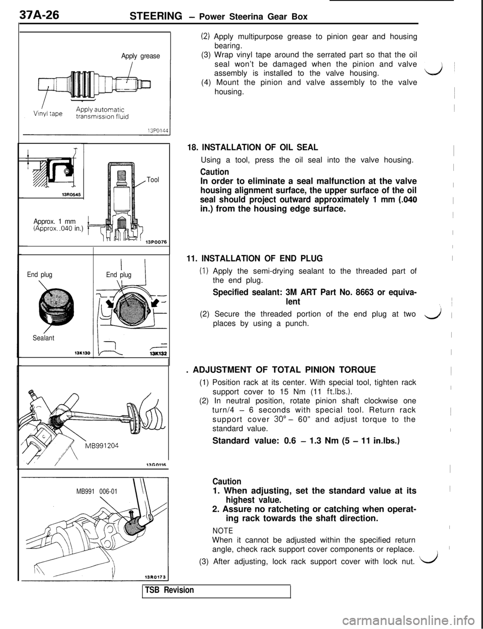
(2) Apply multipurpose grease to pinion gear and housing
bearing.(3) Wrap vinyl tape around the serrated part so that the oil
seal won’t be damaged when the pinion and valve
assembly is installed to the valve housing.
(4) Mount the pinion and valve assembly to the valve
housing.
18. INSTALLATION OF OIL SEALUsing a tool, press the oil seal into the valve housing.
CautionIn order to eliminate a seal malfunction at the valve
housing alignment surface, the upper surface of the oil
seal should project outward approximately 1 mm
(.040in.) from the housing edge surface.
11. INSTALLATION OF END PLUG
(1) Apply the semi-drying sealant to the threaded part of
the end plug.
Specified sealant: 3M ART Part No. 8663 or equiva-
lent(2) Secure the threaded portion of the end plug at two
places by using a punch.
. ADJUSTMENT OF TOTAL PINION TORQUE
(1) Position rack at its center. With special tool, tighten rack
support cover to 15 Nm (11
ft.lbs.1.(2) In neutral position, rotate pinion shaft clockwise one
turn/4
- 6 seconds with special tool. Return rack
support cover 30”
- 60” and adjust torque to the
standard value.
Standard value: 0.6
- 1.3 Nm (5 - 11 in.lbs.)
Caution1. When adjusting, set the standard value at its
highest value.2. Assure no ratcheting or catching when operat-
ing rack towards the shaft direction.
NOTEWhen it cannot be adjusted within the specified return
angle, check rack support cover components or replace.
ii1
I1
I
I
I
I1
I
I
I
I
yl (
I
I1
I1
I
I1
I
I\(3) After adjusting, lock rack support cover with lock nut.
i/
TSB Revision
Page 855 of 1146
STEERING - Power Steering Gear Box3/A-Z/
13A0175
LipMB990776-01
Sealant
I3Y56413AO259
190.6 -192.6mm(7:504 - 7.583in.)
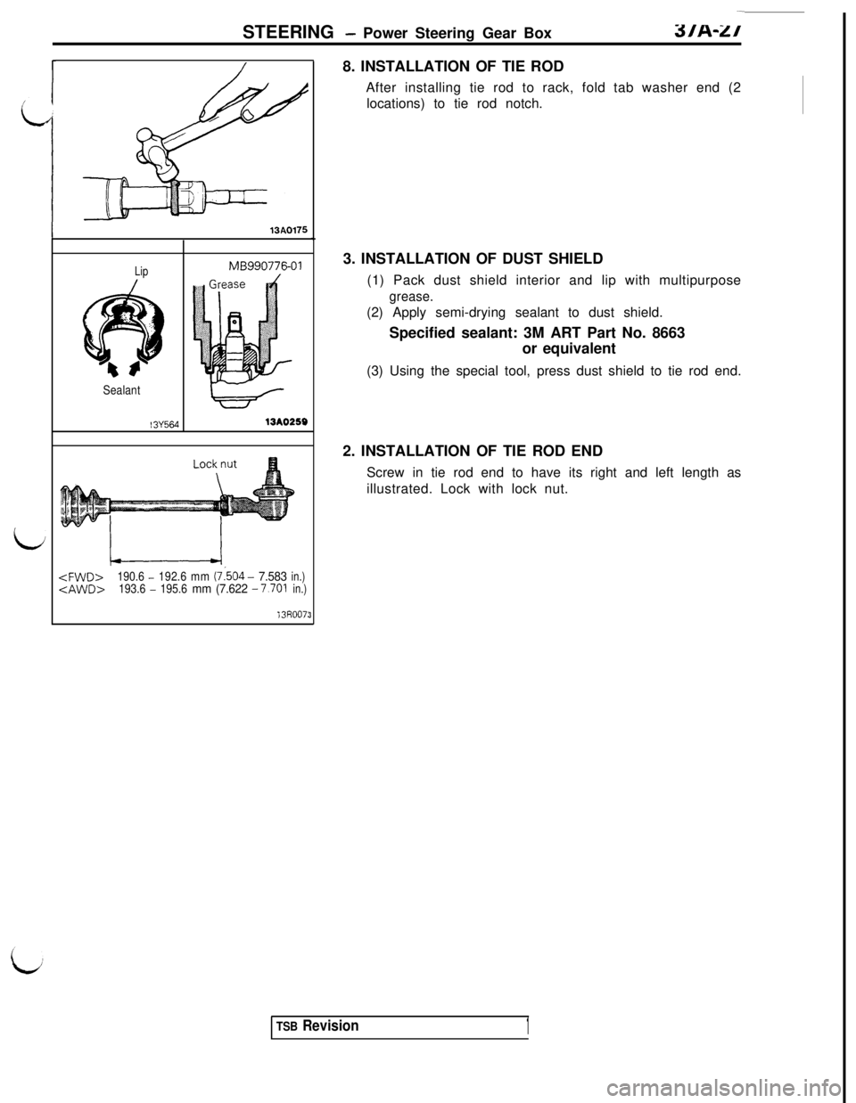
13R007:38. INSTALLATION OF TIE ROD
After installing tie rod to rack, fold tab washer end (2
locations) to tie rod notch.
3. INSTALLATION OF DUST SHIELD
(1) Pack dust shield interior and lip with multipurpose
grease.(2) Apply semi-drying sealant to dust shield.
Specified sealant: 3M ART Part No. 8663
or equivalent
(3) Using the special tool, press dust shield to tie rod end.
2. INSTALLATION OF TIE ROD END
Screw in tie rod end to have its right and left length as
illustrated. Lock with lock nut.
TSB Revision1
Page 856 of 1146
37A-28
STEERING - Power Steering Oil Pump
POWER STEERING OIL PUMP
REMOVAL AND INSTALLATION
I
M37RA-.
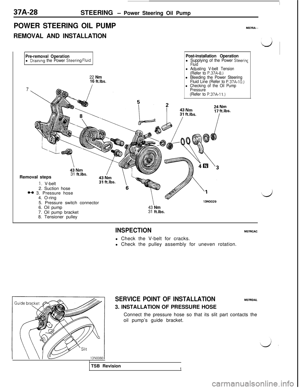
Pre-removal Operationl Draintng the Power Steenng Flurd
22 Nm
16 ft.lbs.
7
Post-installation Operationl Supplying of the Power Steering
Fluid
l Adjusting V-belt Tension(Refer to P.37A-8.)l Bleeding the Power Steering
Fluid Line (Refer to P.37A-10.)l Checking of the Oil Pump
Pressure
(Refer to P.37A-11.)Removal steps
31 ft.lbs.
1. V-belt
2. Suction hose
** 3. Pressure hose
4. O-ring
5. Pressure switch connector
6. Oil pump
7. Oil pump bracket
8. Tensioner pulley
43 Nm31 fklbs.
13N0029
Ij
INSPECTIONM37RCACl Check the V-belt for cracks.
l Check the pulley assembly for uneven rotation.
SERVICE POINT OF INSTALLATIONM37ROAL3. INSTALLATION OF PRESSURE HOSE
Connect the pressure hose so that its slit part contacts the
oil pump’s guide bracket.
TSB Revision
1
Page 857 of 1146
STEERING - Power Steering Oil Pump37A-29
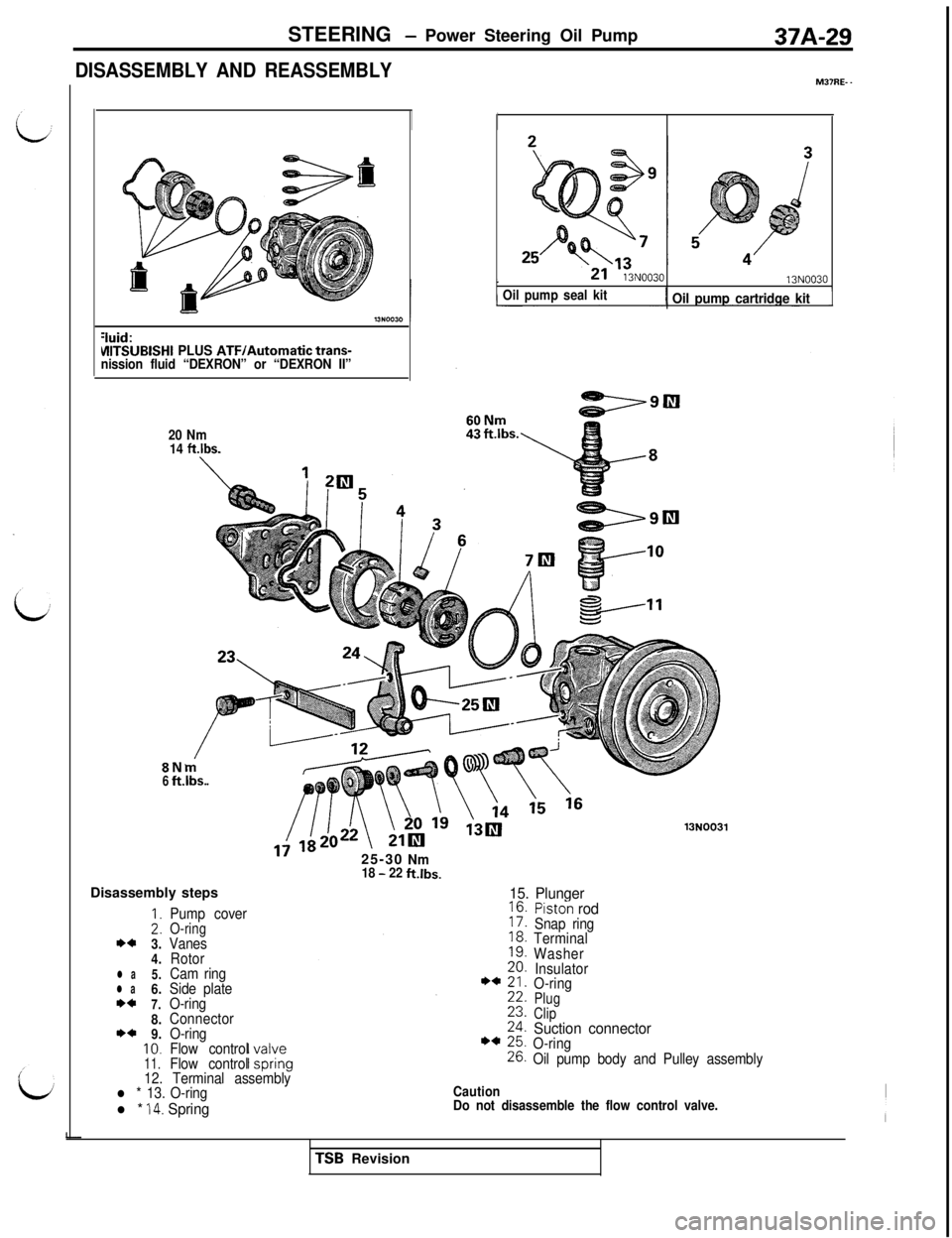
DISASSEMBLY AND REASSEMBLYMS’RE- -
:iuid:VllTSlJBlSHI PLUS ATF/Automatic trans-
nission fluid “DEXRON” or “DEXRON II”
20 Nm
14
ft.lbs.
13N0030
Oil pump seal kit1 Oil pump cartridge kit
8N6ft.lbs.
13N0031Disassembly steps25-30
Nm18 - 22ft.lbs.
15. Plunger
:I*a3.
4.
l a5.l a6.*a7.8.**9.10.
11.
Pump coverO-ringVanes
Rotor
Cam ring
Side plate
O-ring
Connector
O-ring
Flow control
Flow control
Piston rodSnap ring
Terminal
Washer
Insulator
O-ring
Plug
Clip
Suction connectorO-ring
Oil pump body and Pulley assembly
12. Terminal assembly
l * 13. O-ring
l * 14. Spring
Caution
Do not disassemble the flow control valve.TSB Revision
Page 858 of 1146
37A-30STEERING - Power Steering Oil Pump
13R0433
Connector
13K752
Terminal assembly
Side plate613N0059
Suction connector
mounting portion
of oil pump body
13K75313NOOSi
13FOO50
INSPECTIONM37RGAM
l Check the flow control spring for wear.
lCheck the shaft of the pulley for play and round movement.
l Check the groove of rotor vane for “stepped” wear.
l Check the contact surface of cam ring and vanes for
“stepped” wear.
l Check the vanes for breakage.
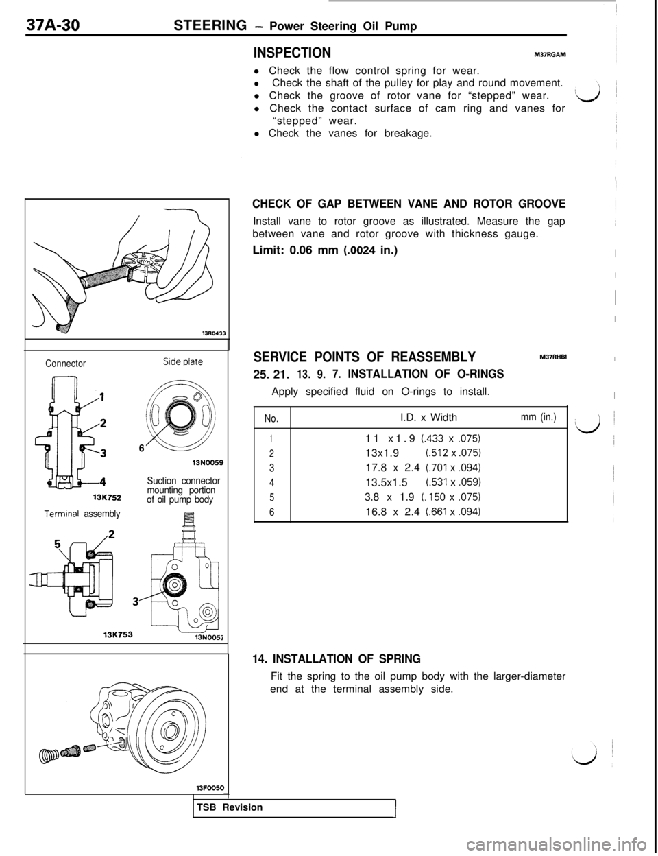
CHECK OF GAP BETWEEN VANE AND ROTOR GROOVEInstall vane to rotor groove as illustrated. Measure the gap
between vane and rotor groove with thickness gauge.
Limit: 0.06 mm
(.0024 in.)
M37RHBISERVICE POINTS OF REASSEMBLY25. 21.
13.9.7.INSTALLATION OF O-RINGSApply specified fluid on O-rings to install.
No.I.D. x Width
111 x1.9 (.433 x ,075)
213x1.9(.512 x ,075)
317.8 x 2.4
(.701 x ,094)
413.5x1.5
(.531 x .059)
53.8 x 1.9 (. 150 x ,075)
616.8 x 2.4
i.661 x ,094)
mm (in.)
I1
I
I
I
I
t i
14. INSTALLATION OF SPRINGFit the spring to the oil pump body with the larger-diameter
end at the terminal assembly side.
TSB Revision
I
Page 859 of 1146
STEERING - Power Steering Oil Pump37A-31 1
Dowel pin
131025i
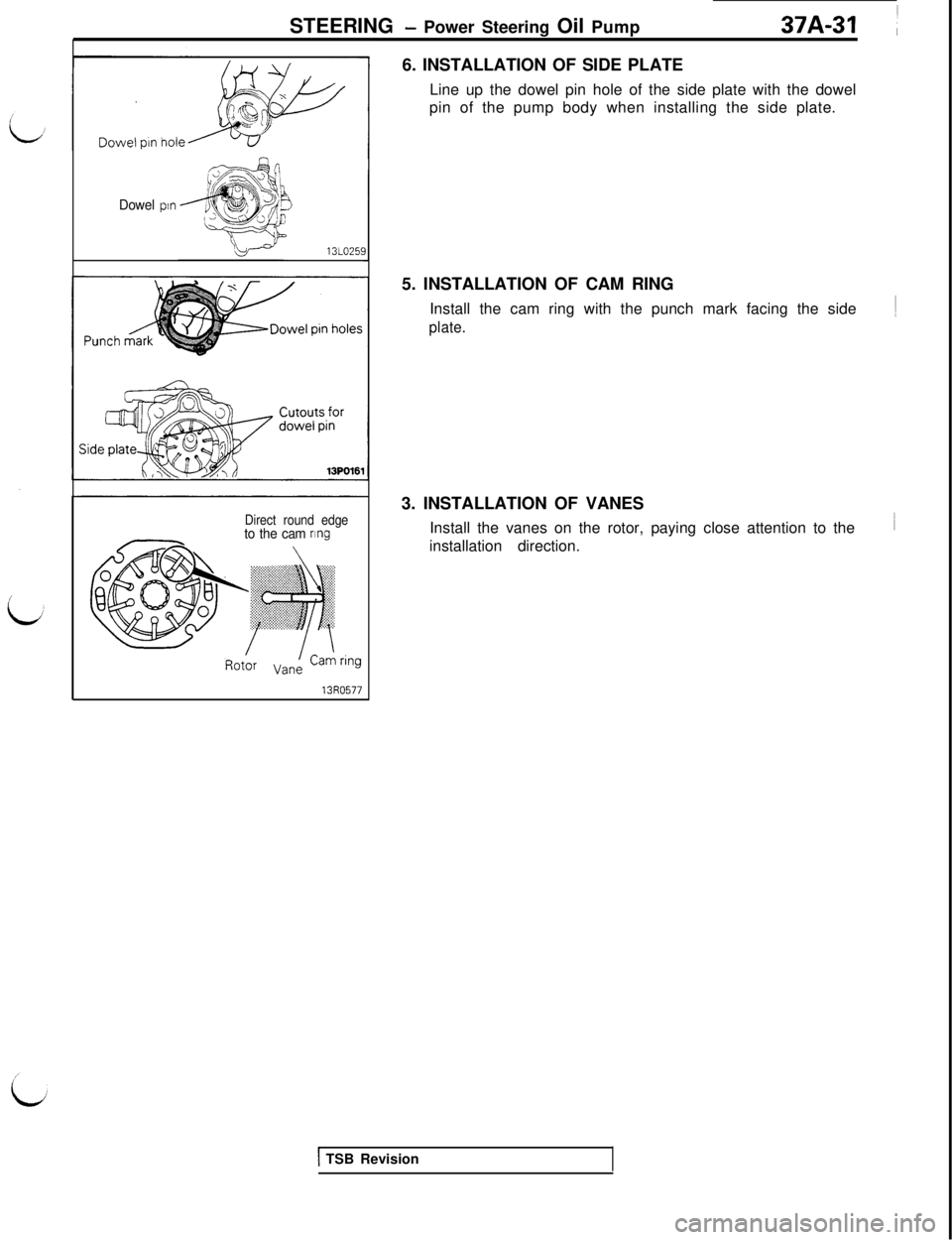
Direct round edgeto the cam nng6. INSTALLATION OF SIDE PLATE
Line up the dowel pin hole of the side plate with the dowel
pin of the pump body when installing the side plate.
5. INSTALLATION OF CAM RING
Install the cam ring with the punch mark facing the side
plate.3. INSTALLATION OF VANES
Install the vanes on the rotor, paying close attention to the
installation direction.
1 TSB Revision
Page 860 of 1146
37A-32STEERING - Power Steering Hoses
POWER STEERING HOSES
REMOVAL AND INSTALLATION
Pre-removal and Post-installation Operation
Il Draining, Supplying, and Bleeding of
the Power Steerina Fluid
(Refer to
P.37A-9,‘iO.)
12 Nm5Nm
8 ftlbs.4 ftlbs.
I12Nm
35Nm
12 Nm25ft.lbs.
8 ftlbs.2
I24 Nm
22 Nm17 f-tlbsad/16 ft.lbs.
11 klbs.
112/Nm8 ftlbs.M37TA.
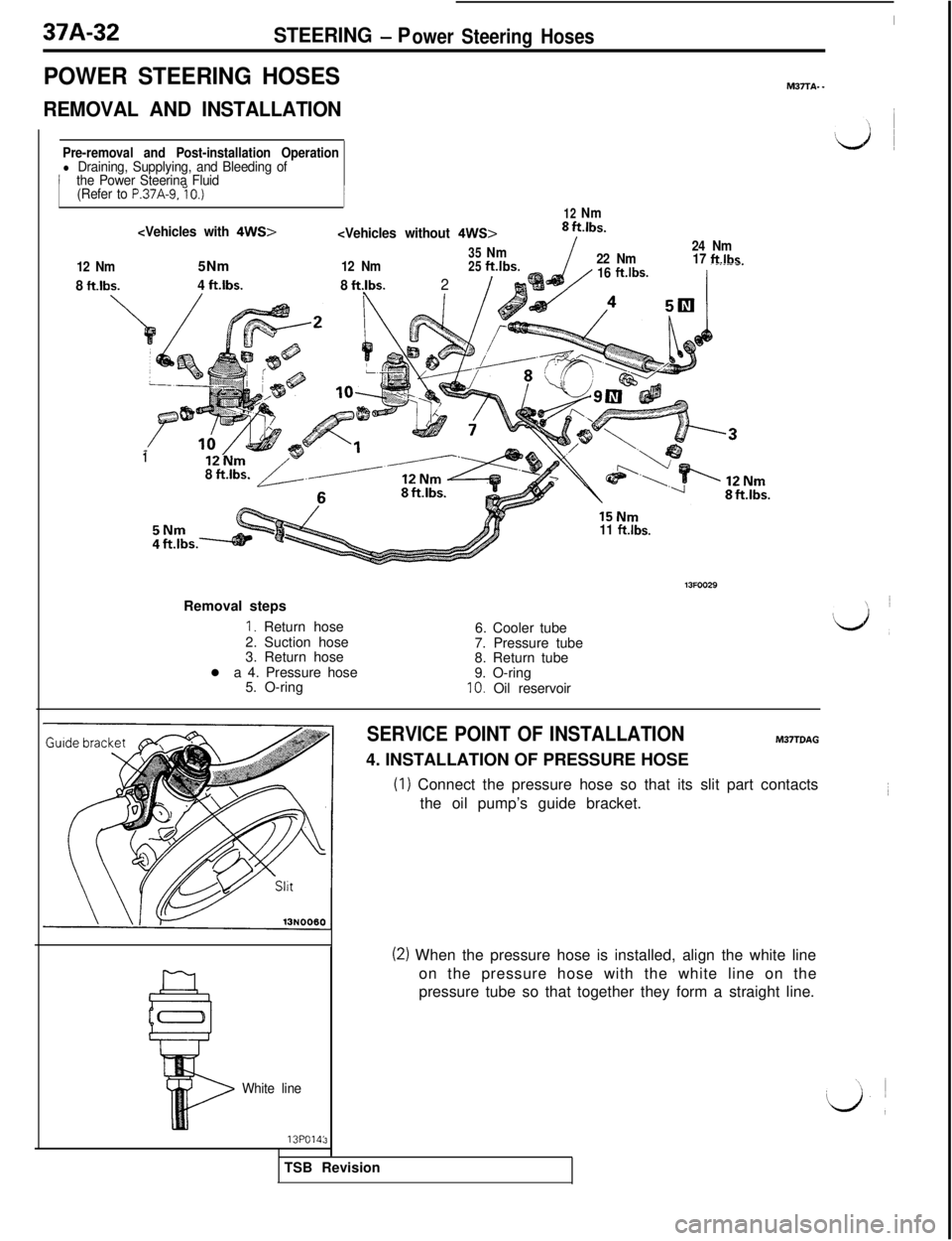
_Removal steps
I. Return hose
2. Suction hose
3. Return hose
l a 4. Pressure hose
5. O-ring6. Cooler tube
7. Pressure tube
8. Return tube
9. O-ring
IO. Oil reservoir
3
White line
13po14:
SERVICE POINT OF INSTALLATIONM3TTDAG
4. INSTALLATION OF PRESSURE HOSE
(1) Connect the pressure hose so that its slit part contacts
the oil pump’s guide bracket.
(2) When the pressure hose is installed, align the white line
on the pressure hose with the white line on the
pressure tube so that together they form a straight line.
TSB Revision