MITSUBISHI 3000GT 1991 Service Manual
3000GT 1991
MITSUBISHI
MITSUBISHI
https://www.carmanualsonline.info/img/19/57085/w960_57085-0.png
MITSUBISHI 3000GT 1991 Service Manual
Trending: oil dipstick, wiring diagram, tow, window, mileage, hood open, light
Page 891 of 1146
BODY -Engine Hood42-I Y18FOOW
!I
II
INSPECTION
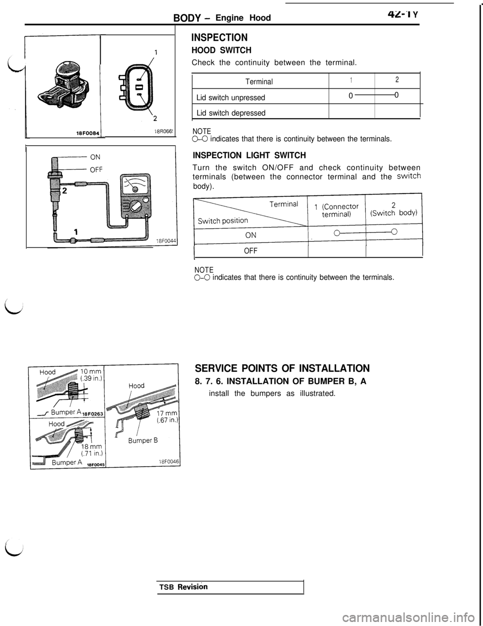
HOOD SWITCHCheck the continuity between the terminal.
Terminal
Lid switch unpressed
Lid switch depressed
1200
NOTEG-0 indicates that there is continuity between the terminals.
INSPECTION LIGHT SWITCHTurn the switch ON/OFF and check continuity between
terminals (between the connector terminal and the
switch
body).
IOFF
NOTE
O-0 indicates that there is continuity between the terminals.
t
SERVICE POINTS OF INSTALLATION8. 7. 6. INSTALLATION OF BUMPER B, A
install the bumpers as illustrated.
TSB
Revish
Page 892 of 1146
42-20BODY- Liftgate
LIFTGATEM420AAU
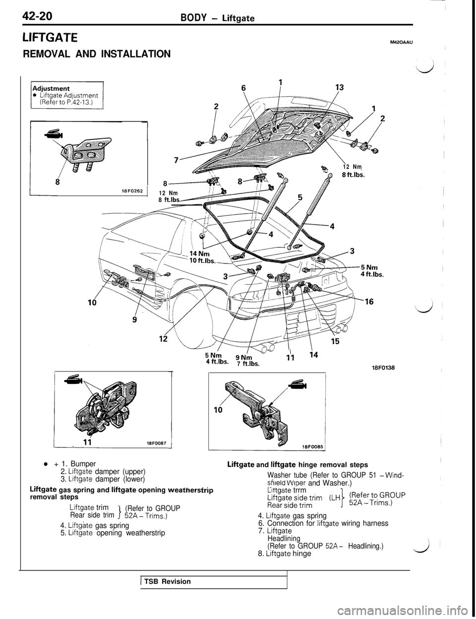
REMOVAL AND INSTALLATION8lSFO262
12 Nm8 ft.lbs.
%a12 Nm
18FOO87
l + 1. Bumper
2. Liftgate damper (upper)
3. Liftgate damper (lower)
1
4, ft.‘bs.1’1 ‘47 ftlbs.18FO138Liftgate and
liftgate hinge removal steps
Washer tube (Refer to GROUP 51 -Wind-
.
. .shield Wtper and Washer.). .._Liftgate gas spring and liftgate opening weatnerstrllp
removal steps
Liftgate trimRear side trim>
(Refer to GROUP52A-Trims.)
4. Liftgate gas spring
5. Liftgate opening weatherstrip
Lrttgate trrmi$ftft;e$d;nm (LH) !!-!-~~~G$)upi
4. Liftgate gas spring
6. Connection for liftgate wiring harness7. LiftgateHeadlining
(Refer to GROUP 52A- Headlining.)8. Liftgate hinge
1 TSB Revision
Page 893 of 1146
BODY - Liftgate42-21
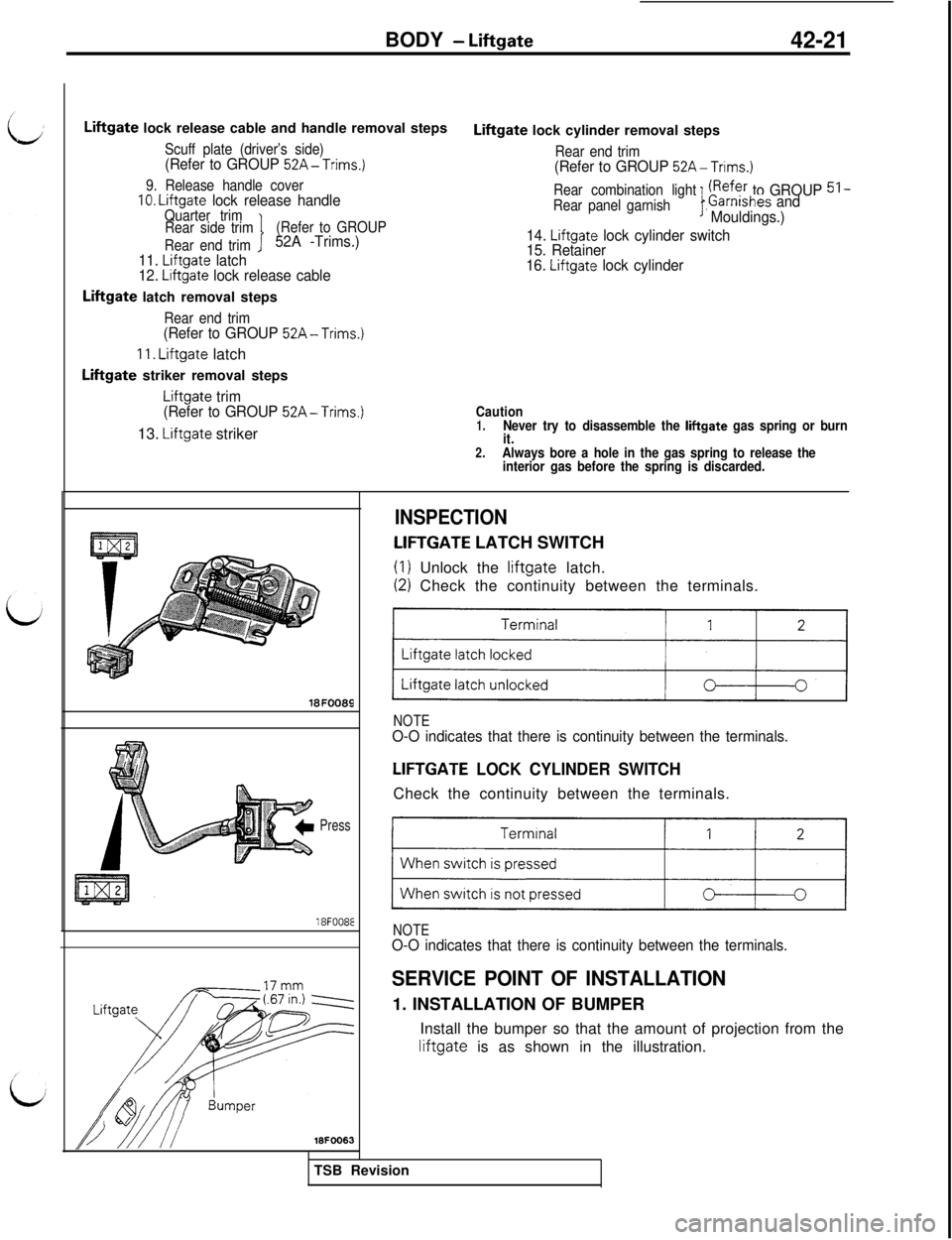
Liftgate lock release cable and handle removal steps
Scuff plate (driver’s side)(Refer to GROUP 52A-Trims.)
9. Release handle cover10. Liftgate lock release handleQuarter trim
Rear side trim(Refer to GROUP
Rear end trim
I52A -Trims.)
11.
Liftgate latch
12. Liftgate lock release cable
Liftgate latch removal steps
Rear end trim(Refer to GROUP 52A-Trims.)
11. Liftgate latch
Liftgate striker removal steps
Liftgate trim
(Refer to GROUP 52A-Trims.)13.
Liftgate strikerLiftgate lock cylinder removal steps
Rear end trim(Refer to GROUP 52A-Trims.)
Rear combination light
I
fRefer to GROUP 51 -Rear panel garnish,Garnishes and
Mouldings.)
14.
Liftgate lock cylinder switch
15. Retainer
16.
Liftgate lock cylinder
Caution1.Never try to disassemble the liftgate gas spring or burn
it.
2.Always bore a hole in the gas spring to release the
interior gas before the spring is discarded.
18FOO89
Press
18F008E
18FOO63
INSPECTION
LIFTGATE LATCH SWITCH
(I) Unlock the liftgate latch.
(2) Check the continuity between the terminals.
)I
NOTEO-O indicates that there is continuity between the terminals.
LIFTGATE LOCK CYLINDER SWITCHCheck the continuity between the terminals.
11
NOTEO-O indicates that there is continuity between the terminals.
SERVICE POINT OF INSTALLATION1. INSTALLATION OF BUMPER
Install the bumper so that the amount of projection from theliftgate is as shown in the illustration.
TSB Revision
Page 894 of 1146
42-22BODY - Fuel Tank Filler Door
FUEL TANK FILLER DOOR
REMOVAL AND INSTALLATION
M42JAAS
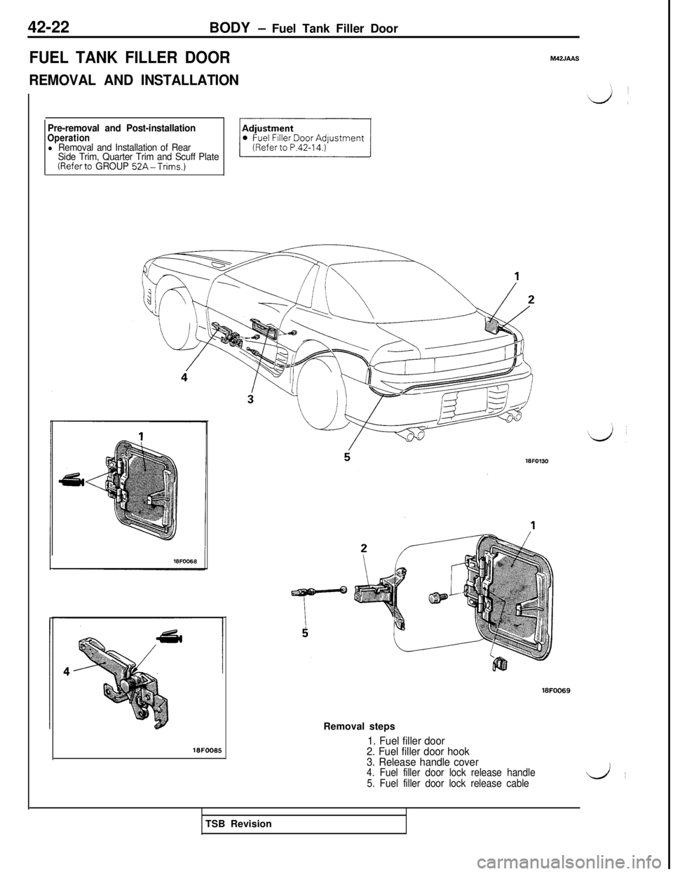
Pre-removal and Post-installationOperationl Removal and Installation of Rear
Side Trim, Quarter Trim and Scuff Plate
(Referto GROUP 52A-Trims.)
18FOO86
18FOO69Removal steps
1. Fuel filler door
2. Fuel filler door hook
3. Release handle cover
4. Fuel filler door lock release handle
5. Fuel filler door lock release cableLA’TSB Revision
Page 895 of 1146
BODY - Fender42-23
FENDER
L
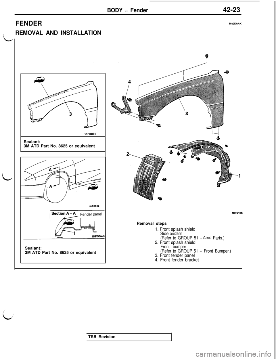
REMOVAL AND INSTALLATIONSealant:
16FOO613M ATD Part No. 8625 or equivalent
18FOO62Sealant:
3M ATD Part No. 8625 or equivalent
M42KAAX
16FO126Removal steps
1. Front splash shield
Side airdam(Refer to GROUP 51 -Aero Parts.)2. Front splash shieldFront bumper
(Refer to GROUP 51 - Front Bumper.)3. Front fender panel
4. Front fender bracketTSB Revision
Page 896 of 1146
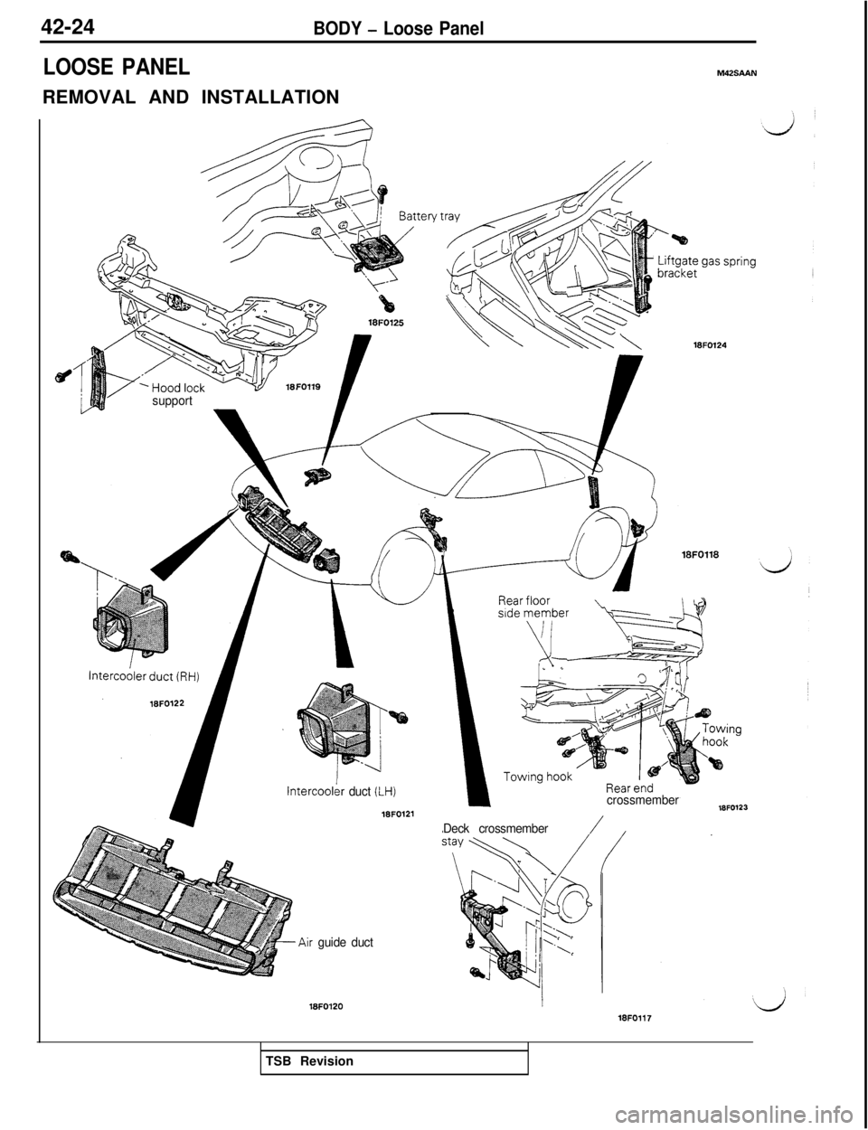
42-24BODY - Loose Panel
LOOSE PANELREMOVAL AND INSTALLATIONM42SAAN
FOllQ
support
lntercoolkr duct (1-H)
16FO121
&Air guide duct
16FOl20
16FO124
Deck crossmember/
crossmember18FO123
18FOll7TSB Revision
Page 897 of 1146
BODY - Window Glass
42-25
WINDOW GLASS
M42LAAL
/GENERAL
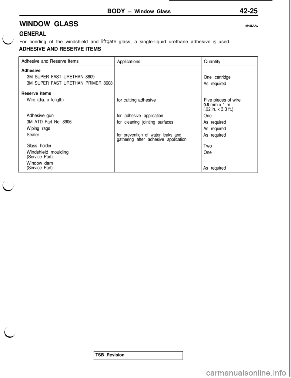
LiFor bonding of the windshield and liftgate glass, a single-liquid urethane adhesive is used.
ADHESIVE AND RESERVE ITEMS
Adhesive and Reserve ItemsApplicationsQuantityAdhesive
3M SUPER FAST URETHAN 8609
One cartridge
3M SUPER FAST URETHAN PRIMER 8608
As requiredReserve items
Wire (dia. x length)for cutting adhesiveFive pieces of wire
0.6 mm x 1 m
f.02 in. x 3.3 ft.)
Adhesive gun
for adhesive application
One
3M ATD Part No. 8906
for cleaning jointing surfaces
As required
Wiping rags
As required
Sealer
for prevention of water leaks and
gathering after adhesive applicationAs required
Glass holder
Two
Windshield moulding
One
(Service Part)
Window dam(Service Part)
As requiredTSB Revision
Page 898 of 1146
42-26
BODY - Window Glass
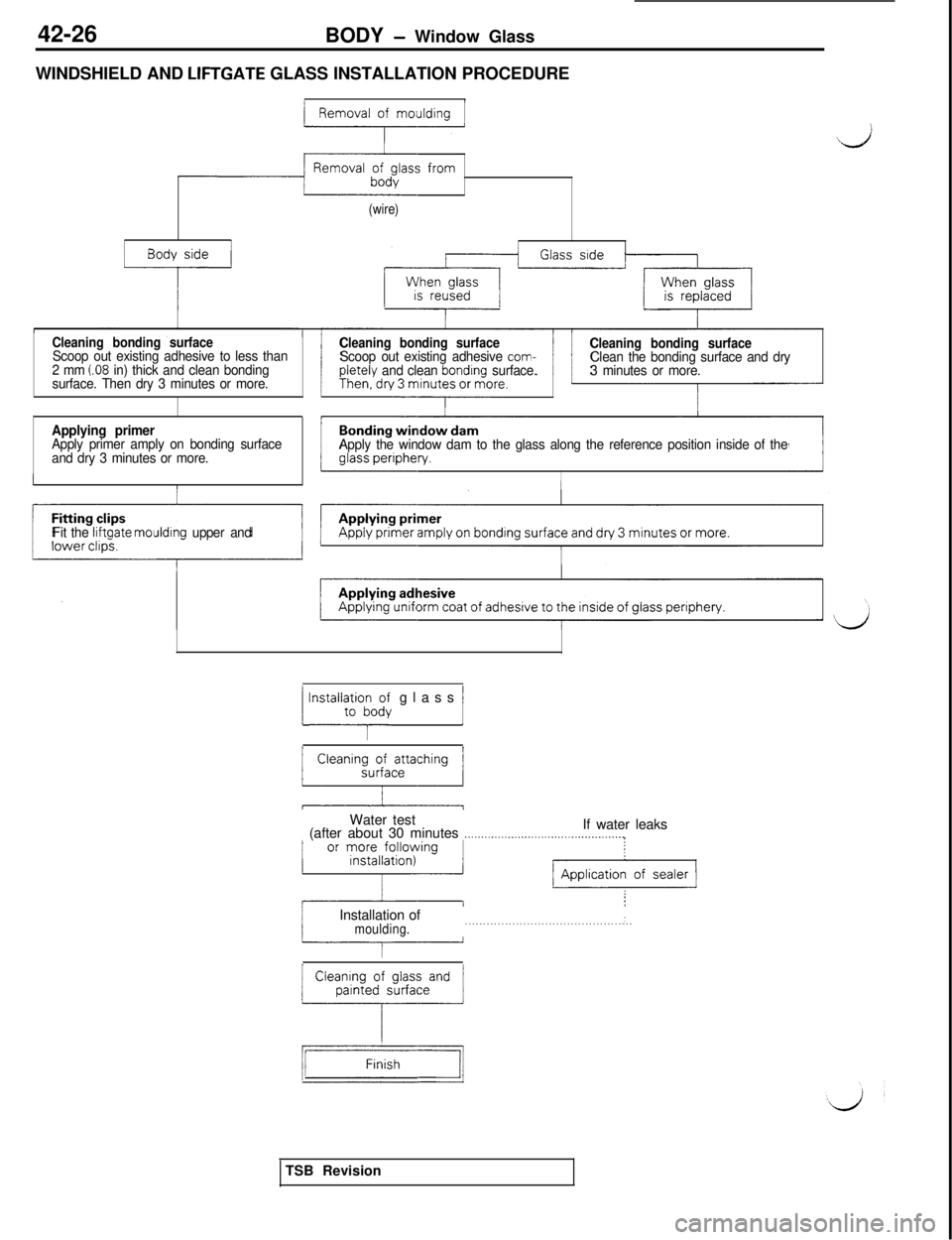
WINDSHIELD AND
LIFTGATE GLASS INSTALLATION PROCEDURE
Removal of
moutding
-4
(wire)
Body side
-i---
Cleaning bonding surfaceScoop out existing adhesive to less than
2 mm (.08 in) thick and clean bonding
surface. Then dry 3 minutes or more.
Cleaning bonding surfaceScoop out existing adhesive com-pletely and clean bondrng surface.
Cleaning bonding surfaceClean the bonding surface and dry
3 minutes or more.
Applying primerApply primer amply on bonding surface
and dry 3 minutes or more.Apply the window dam to the glass along the reference position inside of the
I
Fit the liftgate mouldrng upper and
1 lnstall;rtoio~;~ glass 1Water test
If water leaks
(after about 30 minutes
_............__,,,__........,........,.....,,,..,
IInstallation ofmoulding.. . . . . . . . . . . . . . . . . . . . . . . . . . . . . . . . . . . . . . . . . . . . . . ..~
Cleaning of glass andpainted surface
L
--ITSB Revision
Page 899 of 1146
BODY -Window Glass42-27
/
L
Recommended tool
Make the tool by
Sharpen the edge here4mm(.16in.)18UO161
emove here
lsuo16a/
Upper portion of moulding
Apply primer
Lower portion of moulding
Mou’ding v
18FOO51
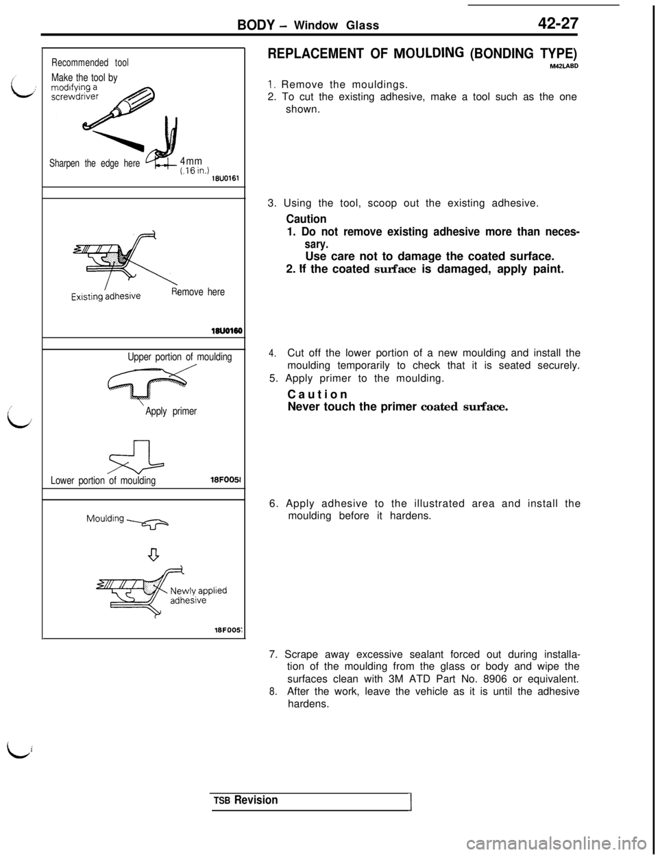
REPLACEMENT OF MOULDING (BONDING TYPE)M42LA80
1. Remove the mouldings.
2. To cut the existing adhesive, make a tool such as the one
shown.
3. Using the tool, scoop out the existing adhesive.
Caution
1. Do not remove existing adhesive more than neces-
sary.Use care not to damage the coated surface.
2.
If the coated surface is damaged, apply paint.
4.Cut off the lower portion of a new moulding and install the
moulding temporarily to check that it is seated securely.
5. Apply primer to the moulding.
Caution
Never touch the primer coated surface.
6. Apply adhesive to the illustrated area and install the
moulding before it hardens.
7. Scrape away excessive sealant forced out during installa-
tion of the moulding from the glass or body and wipe the
surfaces clean with 3M ATD Part No. 8906 or equivalent.
8.After the work, leave the vehicle as it is until the adhesive
hardens.
Li
TSB RevisionI
Page 900 of 1146
42-28
BODY - Windshield
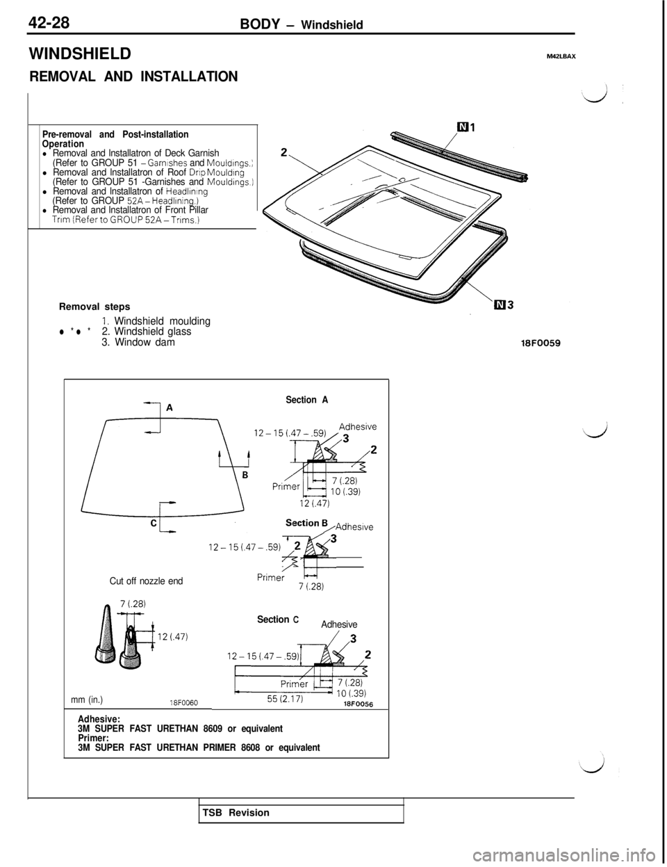
WINDSHIELD
REMOVAL AND INSTALLATION
M42LBAX
Pre-removal and Post-installation
Operation
l Removal and lnstallatron of Deck Garnish
(Refer to GROUP 51 - Garnrshes and Mouldrngs.;l Removal and lnstallatron of Roof Drop Mouldrng(Refer to GROUP 51 -Garnishes and Mouldings.]l Removal and lnstallatron of Headlrnrng(Refer to GROUP 52A- Headlrning.)l Removal and lnstallatron of Front PillarTrim (RefertoGROUP52A-Tnms.)
Removal steps
1. Windshield mouldingl * l *2. Windshield glass
3. Window dam
18FOO59
Cut off nozzle end
mm (in.)18FOO60
Section ASection =,Adheswe
12-l5..47-.59jT;F,<
/
Section CAdhesive
Adhesive:
3M SUPER FAST URETHAN 8609 or equivalent
Primer:
3M SUPER FAST URETHAN PRIMER 8608 or equivalentTSB Revision
Trending: jump start terminals, tires, mileage, oil viscosity, wiring diagram, window, remove seats
