MITSUBISHI 3000GT 1991 Service Manual
Manufacturer: MITSUBISHI, Model Year: 1991, Model line: 3000GT, Model: MITSUBISHI 3000GT 1991Pages: 1146, PDF Size: 76.68 MB
Page 821 of 1146
PARKING BRAKES - Parking Brake Lever and Parking Brake Cable
PARKING BRAKE LEVER AND PARKING BRAKE CABLE36-5
:
M36WA- _I
/REMOVAL AND INSTALLATION
i
r-remwal Operationl Removal of Front and Rear Console(Refer to GROUP 52A-Console Box.)
Post-installation Operationl Parking Brake Lever Stroke Adjustment
(Refer to P.36-4.)l Installation of Front and Rear Console(Refer to GROUP 52A-Console Box.)
14FOO67
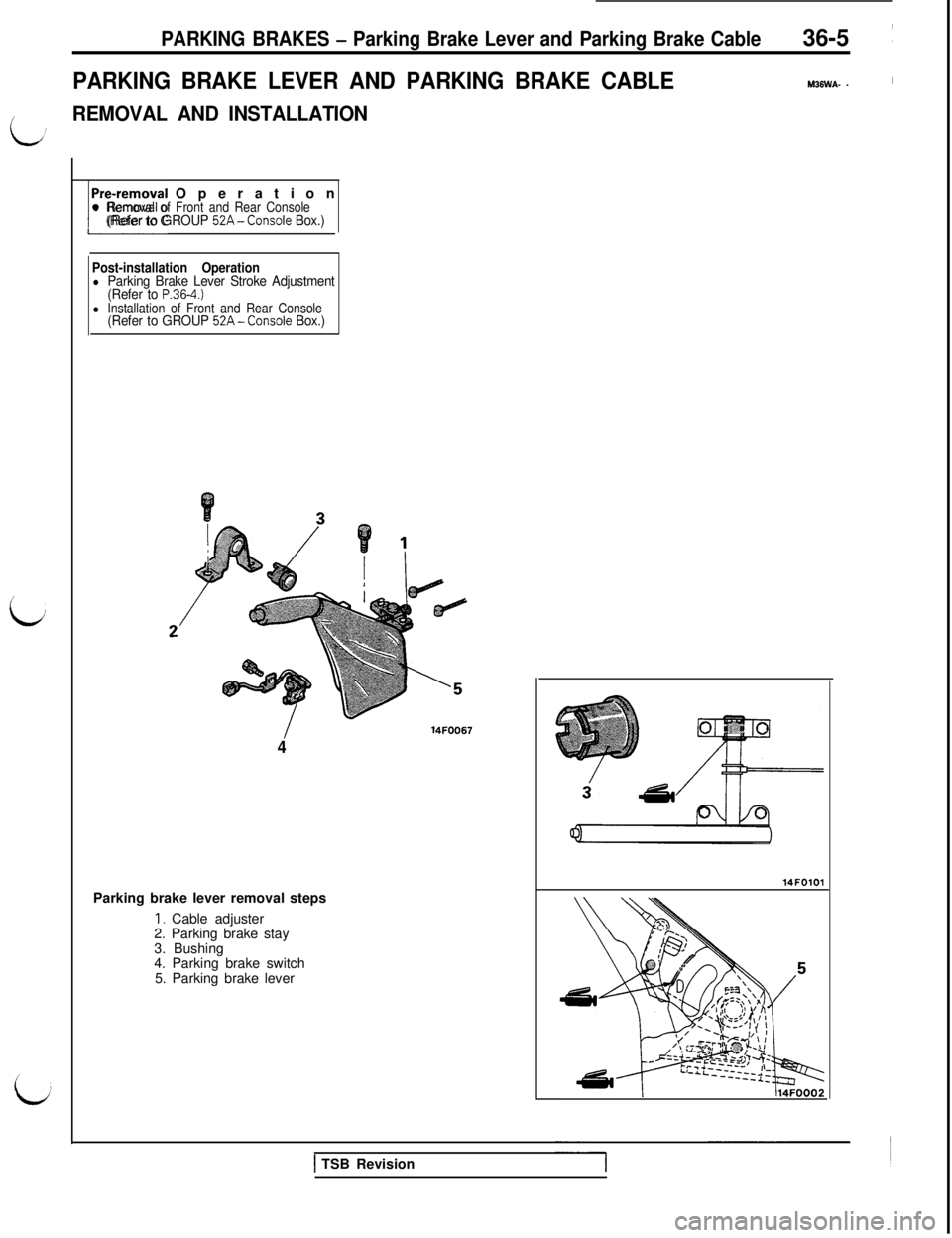
4Parking brake lever removal steps
1. Cable adjuster
2. Parking brake stay
3. Bushing
4. Parking brake switch
5. Parking brake lever14FOlOl
1 TSB Revision
Page 822 of 1146
36-6PARKING BRAKES - Parking Brake Lever and Parking Brake CableI
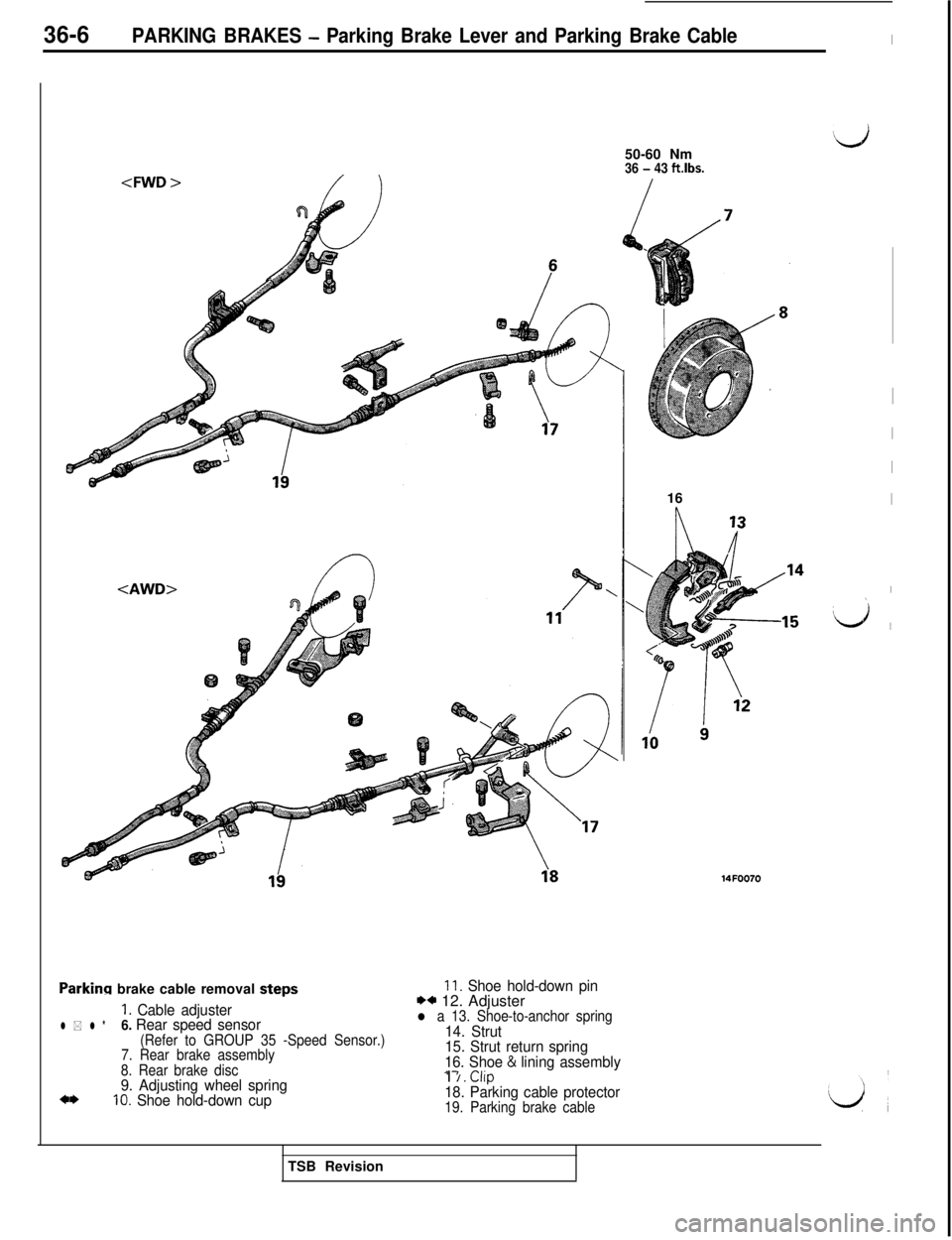
steDs11. Shoe hold-down pin.
1. Cable adjuster** 12. Adjuster
l * l *6. Rear speed sensorl a 13. Shoe-to-anchor spring
(Refer to GROUP 35 -Speed Sensor.)14. Strut
7. Rear brake assembly15. Strut return spring
8. Rear brake disc16. Shoe & lining assembly*-I PI’.
9. Adjusting wheel spring10. Shoe hold-down cupI
/. Llrp18. Parking cable protector19. Parking brake cable16
I
I
I
I
I\
‘d ~
14FOO70TSB Revision
Page 823 of 1146
PARKING BRAKES -Parking Brake Lever and Parking Brake Cable36-7
14N000'
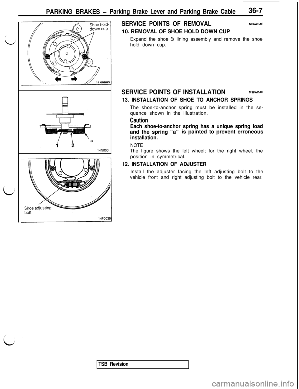
SERVICE POINTS OF REMOVALM36WBAE10. REMOVAL OF SHOE HOLD DOWN CUP
Expand the shoe & lining assembly and remove the shoe
hold down cup.
SERVICE POINTS OF INSTALLATIONMJBWOAH
13. INSTALLATION OF SHOE TO ANCHOR SPRINGSThe shoe-to-anchor spring must be installed in the se-
quence shown in the illustration.
Caution
Each shoe-to-anchor spring has a unique spring loadand the spring “a”is painted to prevent erroneous
installation.
NOTEThe figure shows the left wheel; for the right wheel, the
position in symmetrical.
12. INSTALLATION OF ADJUSTERInstall the adjuster facing the left adjusting bolt to the
vehicle front and right adjusting bolt to the vehicle rear.
TSB Revision
Page 824 of 1146
36-8PARKING BRAKES - Parking Brake
PARKING BRAKE
REMOVAL AND INSTALLATION
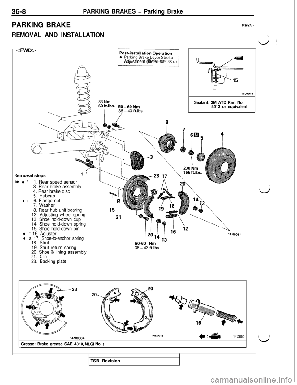
C* l *1. Rear speed sensor
3. Rear brake assembly
4. Rear brake disc
5.Hubcap
l +6. Flange nut7.Washer
8. Rear hub unit
beanng12. Adjusting wheel spring
13. Shoe hold-down cup
14. Shoe hold-down spring
15. Shoe hold-down pin
l * 16. Adjusterl a 17. Shoe-to-anchor spring18.Strut
19. Strut return spring
20. Shoe
& lining assembly21.Clip23.Backingplate
71
Adjustment (Refer to P.36.4.)
83 Nm60ft.lbS. 50-60Nm
36 - 43 ft.lbs.
/
M36YA- -
Sealant: 3M ATD Part No.
8513 or equivalent50-60 Nm
36 - 43 ftlbs.
14NOOll
L23
20
*
14N0004
Grease: Brake grease SAE J310, NLGI No. 1
14LOO15c:&14D650
d,
I
ITSB Revision
Page 825 of 1146
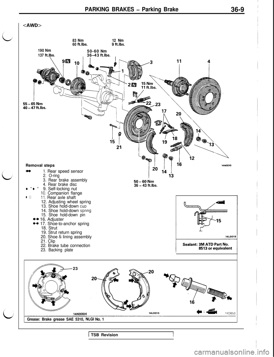
PARKING BRAKES - Parking Brake36-9
4WD>
190Nm
137ft.lbs.
83Nm12 Nm60ft.lbs.9 ft.lbs.50-60
Nm36 43-ft.lbs.Removal steps
+*I. Rear speed sensor2. O-ring
3. Rear brake assembly
4. Rear brake disc
50-60Nm36 - 43 ft.lbs.l * l *9. Self-locking nut10. Companion flangel *11. Rear axle shaft
12. Adjusting wheel spring
13. Shoe hold-down
CUD14. Shoe hold-down spnng15. Shoe hold-down pinI)* 16. AdjusterI)* 17. Shoe-to-anchor spring
18. Strut
19. Strut return spring
20. Shoe
& lining assembly
21. Clip
22. Brake tube connection
23. Backing plate23
Grease: Brake grease SAE 5310, NLGI No. 1
1 TSB Revision1
Page 826 of 1146
36-10PARKING BRAKES - Parking Brake
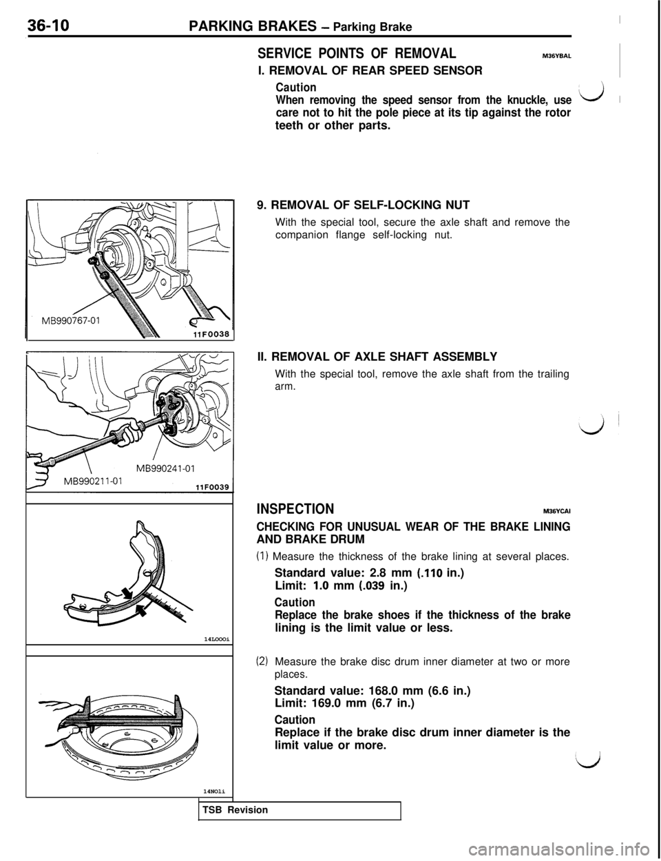
SERVICE POINTS OF REMOVALM36YBALI. REMOVAL OF REAR SPEED SENSOR
Caution
When removing the speed sensor from the knuckle, usei&J 1
care not to hit the pole piece at its tip against the rotorteeth or other parts.
11 FO03814LOOOi
14NOli9. REMOVAL OF SELF-LOCKING NUT
With the special tool, secure the axle shaft and remove the
companion flange self-locking nut.
II. REMOVAL OF AXLE SHAFT ASSEMBLY
With the special tool, remove the axle shaft from the trailing
arm.
INSPECTIONM36YCAI
CHECKING FOR UNUSUAL WEAR OF THE BRAKE LININGAND BRAKE DRUM
(1) Measure the thickness of the brake lining at several places.
Standard value: 2.8 mm
(.I10 in.)
Limit:
1.0 mm (.039 in.)
Caution
Replace the brake shoes if the thickness of the brakelining is the limit value or less.
(2)Measure the brake disc drum inner diameter at two or more
places.Standard value: 168.0 mm (6.6 in.)
Limit: 169.0 mm (6.7 in.)
CautionReplace if the brake disc drum inner diameter is the
limit value or more.
TSB Revision
Page 827 of 1146
PARKING BRAKES - Parking Brake36-11
14N000'
Spindle,
I’_14NOO05
SERVICE POINTS OF INSTALLATIONM36YDAP
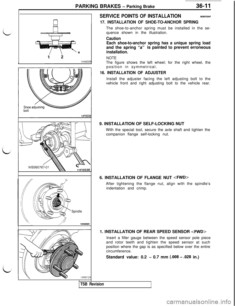
17. INSTALLATION OF SHOE-TO-ANCHOR SPRINGThe shoe-to-anchor spring must be installed in the se-
quence shown in the illustration.
Caution
Each shoe-to-anchor spring has a unique spring loadand the spring “a”is painted to prevent erroneous
installation.
NOTEThe figure shows the left wheel; for the right wheel, the
position in symmetrical.
16. INSTALLATION OF ADJUSTERInstall the adjuster facing the left adjusting bolt to the
vehicle front and right adjusting bolt to the vehicle rear.
9. INSTALLATION OF SELF-LOCKING NUT
With the special tool, secure the axle shaft and tighten the
companion flange self-locking nut.
6. INSTALLATION OF FLANGE NUT
indentation and crimp.
1. INSTALLATION OF REAR SPEED SENSOR
and rotor teeth and tighten the speed sensor at such
position where the gap is as specified below over the entire
circumference.
Standard value: 0.2
- 0.7 mm (.008 - .028 in.)
TSB Revision
Page 828 of 1146

Page 829 of 1146
37A-1
STEERING
CONTENTSM37AA-A
POWER STEERING GEAR BOX*....................17Steering Wheel Return to Center
Check................................................................8
POWER STEERING HOSES................................32Tie Rod End Ball Joint Startinq Torque
POWER STEERING OIL PUMP. .._....................28Check. . . . . . . . .._.............................. r . . . . . . . . ..I . . . . . .6Tie Rod End Ball Joint Variation Check
SERVICE ADJUSTMENT PROCEDURES5(Shaft direction)................................................5........
Bleeding............................................................10V-Belt Tension Check........................................8
Fluid Level Check............................................9SPECIAL TOOLS....................................................3Fluid Replacement
............................................9
/
bOil Pressure Switch Check
SPECIFICATIONS2............................12................................................Oil Pump Pressure Test
....................................1 1General Specifications....................................2Stationary Steering Effort Check
....................8Lubricants............................................................3Steering Angle Check
5Sealant and Adhesives....................................3........................................Steering Wheel Centering
6Service Specifications....................................2................................Steering Wheel Free Play Check
....................5STEERING WHEEL AND SHAFT*....................13
SUPPLEMENTAL RESTRAINT SYSTEM (SRS)
(1)A Supplemental Restraint System (SRS), which uses a driver-side air bag, has been installed in the 3000GT.(2)The SRS includes the following components: impact sensors, SRS diagnosis unit: SRS warning light, air bagmodule, clock spring, interconnecting wiring. Other SRS-related components (that may have to be
removed/installed in connection with SRS service or maintenance) are indicated in the table of contents byan asterisk (*).
WARNING!(I)Improper service or maintenance of any component of the SRS, or any SRS-related component, can lead to
personal injury or death to service personnel (from inadvertent firing of the air bag) or to the driver (from
rendering the SRS inoperative).
(2) Service or maintenance of any SRS component or SRS-related component must be performed only at an
authorized MITSUBISHI dealer.(3) MITSUBISHI dealer personnel must thoroughly review this manual, and especially its GROUP 52B
-Supplemental Restraint System (SRS), before beginning any service or maintenance of any component of theSRS or any SRS-related component.
Page 830 of 1146
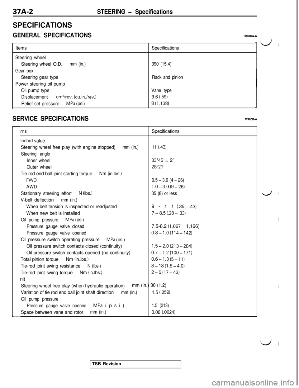
37A-2SPECIFICATIONS
STEERING - Specifications
GENERAL SPECIFICATIONS
M37CA-A
LA,Items
Steering wheel
Steering wheel O.D.
mm (in.)
Gear box
Steering gear type
Power steering oil pump
Oil pump type
Displacementcm3/rev. (cu.in./rev.)
Relief set pressureMPa (psi)
Specifications
390 (15.4)
Rack and pinion
Vane type
9.6 t.59)
8(1,138)
SERVICE SPECIFICATIONSM37CB-A
!msSpecifications
andard value
Steering wheel free play (with engine stopped)
mm (in.)11 (43)
Steering angle
Inner wheel33”45’ 2 2”
Outer wheel28”21’
Tie rod end ball joint starting torqueNm (in.lbs.)
FWD0.5 - 3.0 (4 - 26)
AWDl.O-3.0(9-26)
Stationary steering effortN (Ibs.)35 (8) or less
V-belt deflectionmm (in.)
When belt tension is inspected or readjusted9-11 (.35-.43)
When new belt is installed7 - 8.5 (.28 - .33)
Oil pump pressureMPa (psi)
Pressure gauge valve closed7.5-8.2 (1,067- 1,166)
Pressure gauge valve opened0.8-1.0(114-142)
Oil pressure switch operating pressureMPa (psi)
Oil pressure switch contacts closed (continuity)
1.5-2.0(213-284)
Oil pressure switch contacts opened (no continuity)0.7-1.2(100-171)
Total pinion torqueNm (in.lbs.)0.6-1.3(5-11)
Tie-rod joint swing resistanceN (Ibs.)8-18(1.8-4.0)
Tie-rod joint swing torqueNm (in.lbs.)2-5(17-43)nit
Steering wheel free play (when hydraulic operation)mm (in.) 30 (1.2)
Variation of tie rod end ball joint shaft direction
mm (in.)1.5 i.059)
Oil pump pressure
Pressure gauge valve opened
MPa (psi)1.5 (213)
Space between vane and rotormm (in.)0.06 (0024)
LJ’
I
I
L’l
1 TSB Revision