MITSUBISHI 3000GT 1991 Service Manual
Manufacturer: MITSUBISHI, Model Year: 1991, Model line: 3000GT, Model: MITSUBISHI 3000GT 1991Pages: 1146, PDF Size: 76.68 MB
Page 811 of 1146
L
SERVICE BRAKES - Wheel Speed Sensor (ABS)35-89
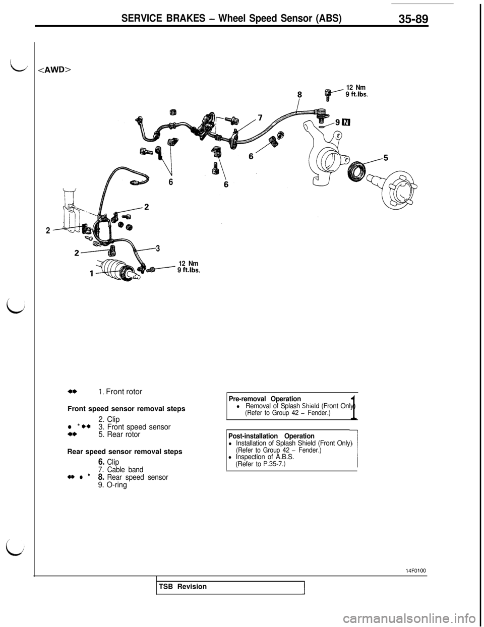
12 Nm9 ft.lbs.
6
2
3
12 Nm- 9 ft.lbs.
a*I, Front rotor
Front speed sensor removal steps
2. Clipl * I)*3. Front speed sensora*5. Rear rotorRear speed sensor removal steps
6. Clip
7. Cable band
+I) l *8. Rear speed sensor9. O-ringPre-removal Operation
lRemoval of Splash Shield (Front Only)(Refer to Group 42 - Fender.)1
Post-installation Operationl Installation of Splash Shield (Front Only)(Refer to Group 42 - Fender.)l Inspection of A.B.S.
(Refer to P.35-7.)14FOlOO
TSB Revision
Page 812 of 1146
SERVICE BRAKES - Wheel Speed Sensor (ABS)
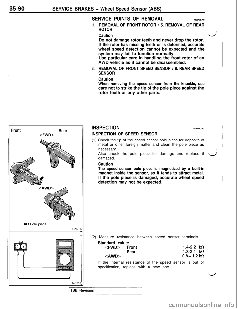
IFrontRear
+ : Pole piece14N016:14NOlO:
SERVICE POINTS OF REMOVALM35OBAC
1.REMOVAL OF FRONT ROTOR / 5. REMOVAL OF REAR
ROTOR
CautiondDo not damage rotor teeth and never drop the rotor.
If the rotor has missing teeth or is deformed, accuratewheel speed detection cannot be expected and the
system may fail to function normally.
Use particular care in handling the front rotor of an
AWD vehicle as it cannot be disassembled.
3.REMOVAL OF FRONT SPEED SENSOR / 8. REAR SPEED
SENSOR
Caution
When removing the speed sensor from the knuckle, usecare not to strike the tip of the pole piece against the
rotor teeth or any other parts.
INSPECTIONMJSOCAC
INSPECTION OF SPEED SENSOR(1) Check the tip of the speed sensor pole piece for deposits of
metal or other foreign matter and clean the pole piece as
necessary.
Also check the pole piece for damage and replace if
damaged.d
Caution
The speed sensor pole piece is magnetized by a built-in
magnet inside the sensor, so it tends to attract metal.If the pole piece is damaged, accurate wheel speed
detection may not be expected.
(2) Measure resistance between speed sensor terminals.
Standard value:
Rear
kR1.3-2.1
kR
0.8- 1.2 kfl
If the internal resistance of the speed sensor is out of
specification, replace with a new one.
Page 813 of 1146
SERVICE BRAKES - Wheel SDeed Sensor lABSI35-91
/
i
lARnlA6
14N012‘
3
(3) zue$ the speed sensor cable for open circuit and replace if
NOTERemove the cable clamp from the body and, while flexing
the cable near the clamp, check for temporary open circuit.
Also check connector connection and terminal insertion.
INSPECTION OF ROTORCheck the rotor for missing or worn teeth and replace if faulty.
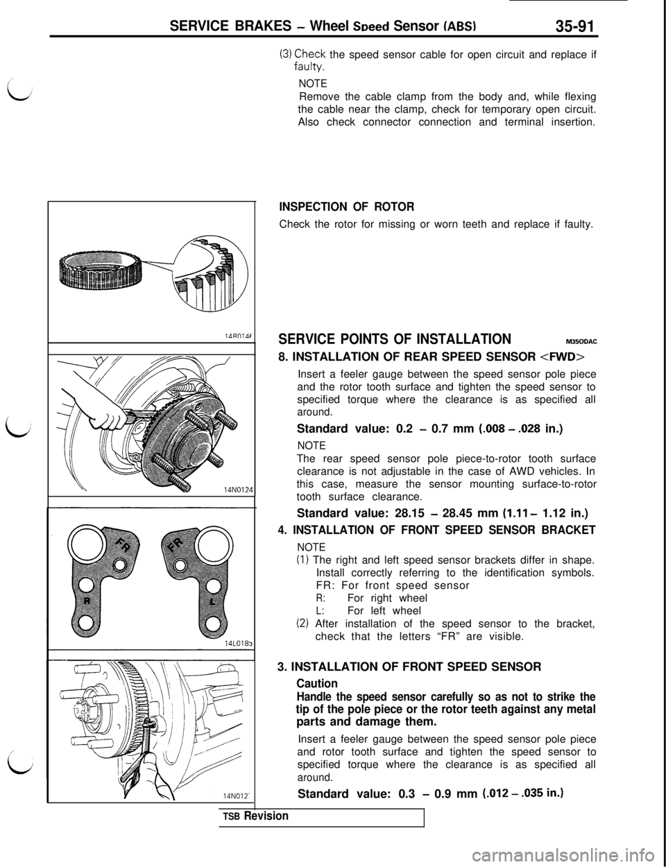
SERVICE POINTS OF INSTALLATIONM350DAC8. INSTALLATION OF REAR SPEED SENSOR
and the rotor tooth surface and tighten the speed sensor to
specified torque where the clearance is as specified all
around.Standard value: 0.2
- 0.7 mm (.008 - .028 in.)
NOTEThe rear speed sensor pole piece-to-rotor tooth surface
clearance is not adjustable in the case of AWD vehicles. In
this case, measure the sensor mounting surface-to-rotor
tooth surface clearance.
Standard value: 28.15
- 28.45 mm (1.11 - 1.12 in.)
4. INSTALLATION OF FRONT SPEED SENSOR BRACKET
NOTE
(I) The right and left speed sensor brackets differ in shape.
Install correctly referring to the identification symbols.
FR: For front speed sensor
R:For right wheel
L:For left wheel
(2) After installation of the speed sensor to the bracket,
check that the letters “FR” are visible.
3. INSTALLATION OF FRONT SPEED SENSOR
Caution
Handle the speed sensor carefully so as not to strike the
tip of the pole piece or the rotor teeth against any metalparts and damage them.
Insert a feeler gauge between the speed sensor pole piece
and rotor tooth surface and tighten the speed sensor to
specified torque where the clearance is as specified all
around.Standard value: 0.3
- 0.9 mm (.012 - .035 in.)
TSB Revision
Page 814 of 1146
35-92SERVICE BRAKES - G Sensor (AWD - ABS)
G SENSOR (AWD
- ABS)
REMOVALINSTALLATION
Pre-removal and Post-installation OperationRemoval and installation of Front
(Refer to Group 52A - Console Box.)
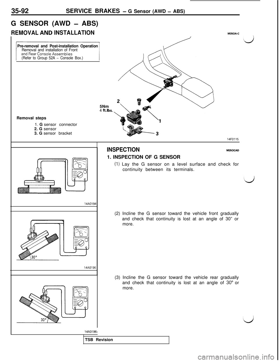
M35OA-C5Nm
4 ft.lbs.Removal steps
1. G sensor connector
2. G sensor
3. G sensor bracket14FO115
114A019)14A0195
14A0196I
INSPECTIONM350CAD1. INSPECTION OF G SENSOR
(I) Lay the G sensor on a level surface and check for
continuity between its terminals.
(2) Incline the G sensor toward the vehicle front gradually
and check that continuity is lost at an angle of 30” or
more.(3) Incline the G sensor toward the vehicle rear gradually
and check that continuity is lost at an angle of 30” or
more.TSB Revision
Page 815 of 1146
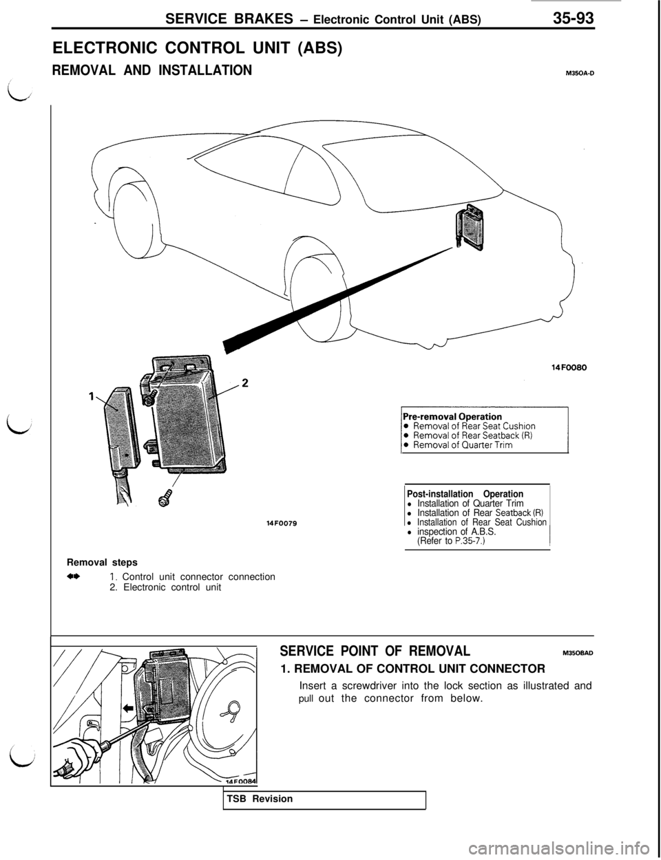
SERVICE BRAKES - Electronic Control Unit (ABS)
ELECTRONIC CONTROL UNIT (ABS)
REMOVAL AND INSTALLATION35-93M350A.D
14FOO79
Post-installation Operationl Installation of Quarter Triml Installation of Rear Seatback (R)l Installation of Rear Seat CushionRemoval steps
4*1, Control unit connector connection
2. Electronic control unit
l inspection of A.B.S.
(Refer to P.35-7.)
SERVICE POINT OF REMOVALM350BAD1. REMOVAL OF CONTROL UNIT CONNECTOR
Insert a screwdriver into the lock section as illustrated and
pull out the connector from below.
TSB Revision
Page 816 of 1146

Page 817 of 1146
36-1
PARKING
BRAKES
CONTENTSM36AA-.
PARKINGBRAKE. . . . . . . . . . . . . . . . . . . . . . . . . . . . . . . . . . . . . . . . . . . . . . . .8SPECIAL TOOLS . .._.._.............................................
PARKING BRAKE LEVER AND PARKINGSPECIFICATIONS................................................
BRAKE CABLE*....................................................5General Specifications....................................
SERVICE ADJUSTMENT PROCEDURES4Lubricants....................................................................Parking Brake Lever Stroke Check4Sealants
andAdhesives....................................................Parking Brake Switch Check
............................4Service Specifications....................................
TROUBLESHOOTING........................................
i
SUPPLEMENTAL RESTRAINT SYSTEM (SRS)
(1)A Supplemental Restraint System (SRS), which uses a driver-side air bag, has been installed in the 3000GT.(2)The SRS includes the following components: impact sensors, SRS diagnosis unit: SRS warning light, air bagmodule, clock spring, interconnecting wiring. Other SRS-related components (that may have to be
removed/installed in connection with SRS service or maintenance) are indicated in the table of contents byan asterisk (*).
WARNING!(1)Improper service or maintenance of any component of the SRS, or any SRS-related component, can lead to
personal injury or death to service personnel (from inadvertent firing of the air bag) or to the driver (fromrendering the SRS inoperative).(2) Service or maintenance of any SRS component or SRS-related component must be performed only at an
authorized MITSUBISHI dealer.(3) MITSUBISHI dealer personnel must thoroughly review this manual, and especially its GROUP 52B
-Supplemental Restraint System (SRS), before beginning any service or maintenance of any component of theSRS or any SRS-related component.
u
I
Page 818 of 1146

36-2PARKING BRAKES - Specifications
SPECIFICATIONSM36CA- -
GENERAL SPECIFICATIONS
ItemsSpecifications
iI”
Parking brakes
Type
Brake lever type
Cable arrangementMechanical brake acting on rear wheels
Lever type
V-type
SERVICE SPECIFICATIONSM36cB-.
Items
Standard value
Parking brake lever stroke
Brake lining thicknessmm (in.)
Brake drum I.D.mm (in.)
Clearance between th;$;;d) sensor pole pieceand the rotor tooth
Limit
Brake lining thicknessmm (in.)
Brake drum I.D.mm (in.)
Specifications
3 - 5 notches2.8
(.I 1)
168.0 (6.6)0.2
- 0.7 LOO8 - .028)
1 .o f.039)
169.0 (6.7)
LUBRICANTSM36CD- -
ditems
Rear brake shoe and backing plate contact surfaces
Contact surface between shoe & lining assembly’sstrut and adjusterSpecified lubricant
Brake grease SAE J310, NLGI No. 1
Contact surface between shoe & lining assembly and
shoe-adjustment bolt and shoe-support piece
SEALANTS AND ADHESIVES
ItemsSpecified sealant
Shoe hold-down pin installation surface3M ATD Part No. 8513 or equivalent
1 TSB Revision
Page 819 of 1146
PARKING BRAKES - Special Tools / Troubleshooting36-3
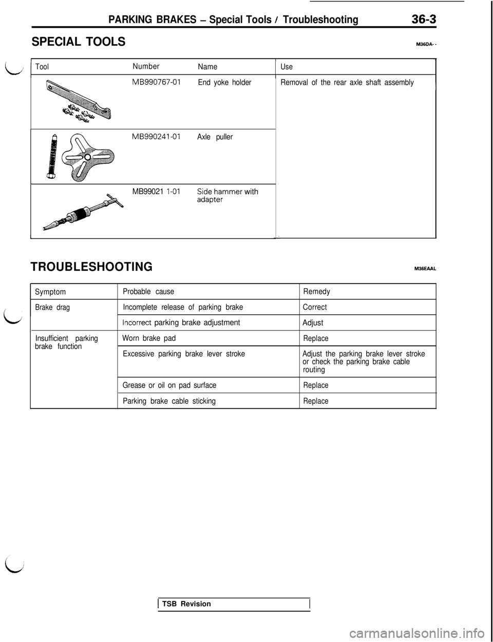
SPECIAL TOOLS
I/
i/ToolNumber
NameUse
IMB990767-01
End yoke holderRemoval of the rear axle shaft assembly1
L
MB990241-01
Axle puller
MB99021 I-01SL$p;;rmmer with
Ii
TROUBLESHOOTINGM36EAAL
Symptom
Brake drag
Insufficient parking
brake functionProbable cause
Incomplete release of parking brake
lndorrect parking brake adjustment
Worn brake padRemedy
Correct
Adjust
Replace
Excessive parking brake lever strokeAdjust the parking brake lever stroke
or check the parking brake cable
routing
Grease or oil on pad surface
Parking brake cable sticking
Replace
Replace
1 TSB Revision
Page 820 of 1146
36-4PARKING BRAKES - Service Adiustment Procedures
-
\Adjusting nut14u015:
un' 14FOO3SERVICE ADJUSTMENT PROCEDURES
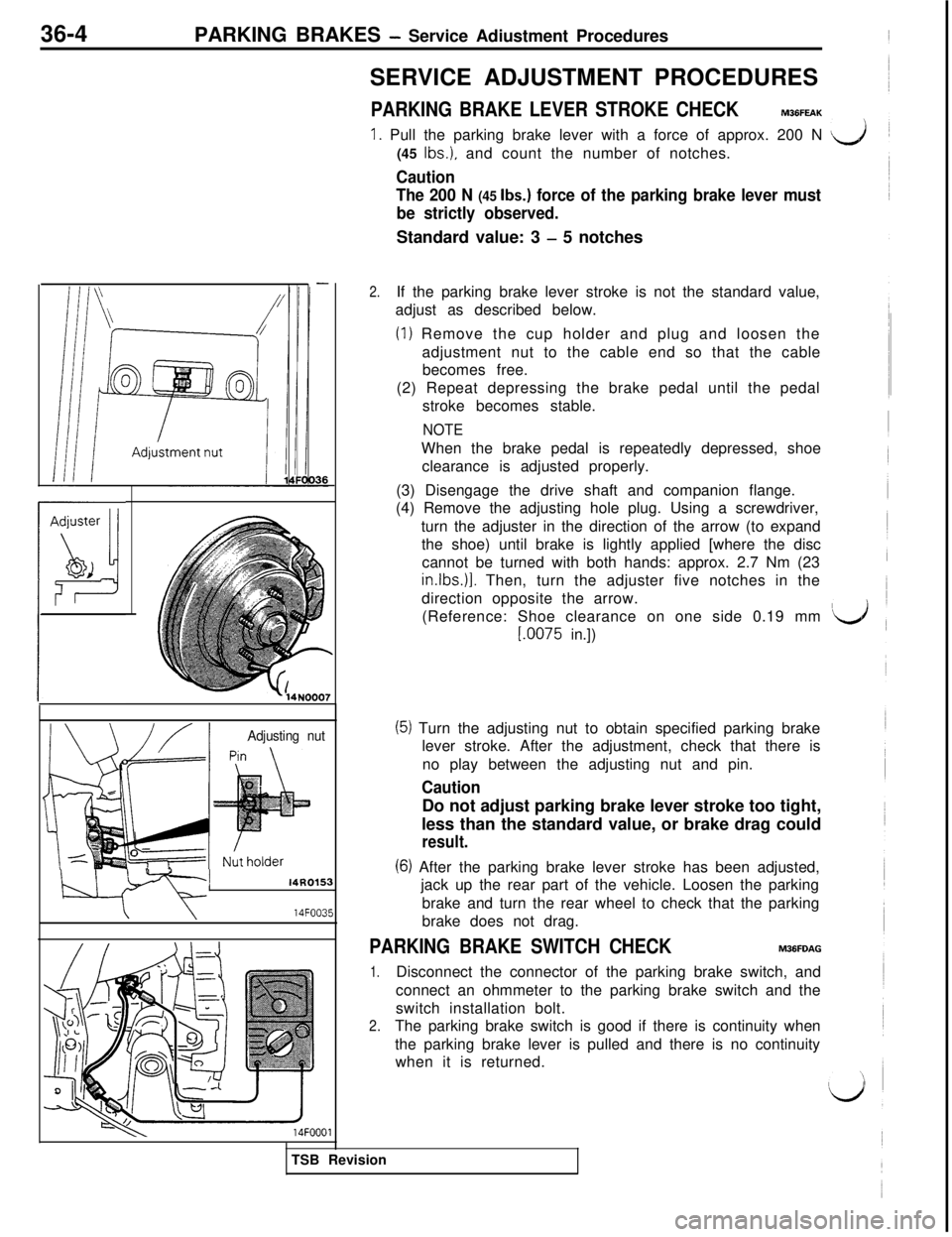
PARKING BRAKE LEVER STROKE CHECKM36FEAK
1. Pull the parking brake lever with a force of approx. 200 N d(45
Ibs.), and count the number of notches.
Caution
The 200 N
(45 Ibs.) force of the parking brake lever must
be strictly observed.Standard value: 3
- 5 notches
2.If the parking brake lever stroke is not the standard value,
adjust as described below.
(1) Remove the cup holder and plug and loosen the
adjustment nut to the cable end so that the cable
becomes free.
(2) Repeat depressing the brake pedal until the pedal
stroke becomes stable.
NOTEWhen the brake pedal is repeatedly depressed, shoe
clearance is adjusted properly.
(3) Disengage the drive shaft and companion flange.
(4) Remove the adjusting hole plug. Using a screwdriver,
turn the adjuster in the direction of the arrow (to expand
the shoe) until brake is lightly applied [where the disc
cannot be turned with both hands: approx. 2.7 Nm (23in.lbs.)]. Then, turn the adjuster five notches in the
direction opposite the arrow.
(Reference: Shoe clearance on one side 0.19 mm
‘d
I.0075 in.])
(6) After the parking brake lever stroke has been adjusted,
jack up the rear part of the vehicle. Loosen the parking
brake and turn the rear wheel to check that the parking
brake does not drag.
PARKING BRAKE SWITCH CHECKM36FDAG
1.Disconnect the connector of the parking brake switch, and
connect an ohmmeter to the parking brake switch and the
switch installation bolt.
2.The parking brake switch is good if there is continuity when
the parking brake lever is pulled and there is no continuity
when it is returned.
,(JTSB Revision
(51 Turn the adjusting nut to obtain specified parking brake
lever stroke. After the adjustment, check that there is
no play between the adjusting nut and pin.
CautionDo not adjust parking brake lever stroke too tight,
less than the standard value, or brake drag could
result.