MITSUBISHI 3000GT 1991 Service Manual
Manufacturer: MITSUBISHI, Model Year: 1991, Model line: 3000GT, Model: MITSUBISHI 3000GT 1991Pages: 1146, PDF Size: 76.68 MB
Page 931 of 1146
BODY - Central Door Locking System
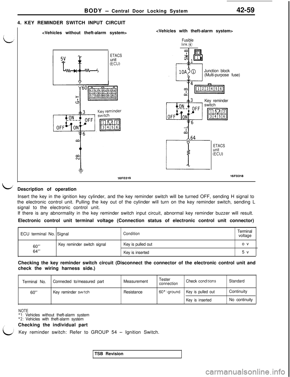
4. KEY REMINDER SWITCH INPUT CIRCUIT42-59
Fusiblelink@
ETACSunit(ECU)
16FO319
Junction block
(Multi-purpose fuse)
Key reminder
switch
ETACSunit(ECU)
16FO318
bDescription of operation
Insert the key in the ignition key cylinder, and the key reminder switch will be turned OFF, sending H signal to
the electronic control unit. Pulling the key out of the cylinder will turn on the key reminder switch, sending L
signal to the electronic control unit.
If there is any abnormality in the key reminder switch input circuit, abnormal key reminder buzzer will result.
Electronic control unit terminal voltage (Connection status of electronic control unit connector)
ECU terminal No. Signal
ConditionTerminal
voltage60”’
Key reminder switch signalKey is pulled outov
64”’
Key is inserted5v
Checking the key reminder switch circuit (Disconnect the connector of the electronic control unit and
check the wiring harness side.)
Terminal No.Connected to/measured partMeasurementTesterconnectionCheck conditronsStandard60”’
Key reminder swatchResistance60*‘-groundKey is pulled outContinuity
Key is insertedNo continuity
NOTE“I : Vehicles without theft-alarm system*2: Vehicles with theft-alarm system
/Checking the individual part
’Key reminder switch: Refer to GROUP 54 - Ignition Switch.
TSB Revision
Page 932 of 1146
42-60
BODY - Central Door Locking System
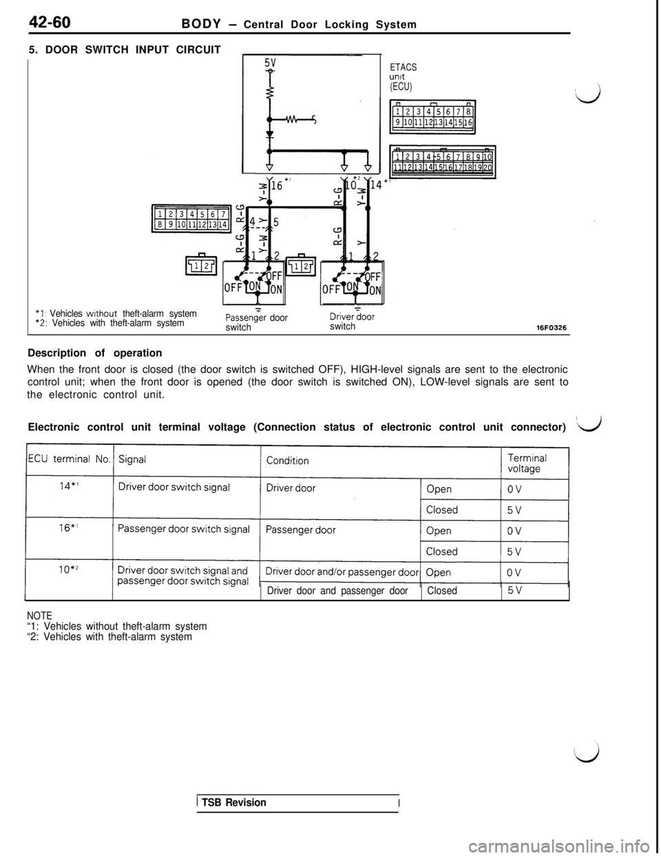
5. DOOR SWITCH INPUT CIRCUIT
ETACSunit(ECU)
*1 : Vehicles without theft-alarm system*2: Vehicles with theft-alarm systemPassen&r door
switchDrivergoorswitch16FO326Description of operation
When the front door is closed (the door switch is switched OFF), HIGH-level signals are sent to the electronic
control unit; when the front door is opened (the door switch is switched ON), LOW-level signals are sent to
the electronic control unit.
Electronic control unit terminal voltage (Connection status of electronic control unit connector)
’d
NOTE
Driver door and passenger doorClosed5v
“1: Vehicles without theft-alarm system
“2: Vehicles with theft-alarm system
1 TSB RevisionI
Page 933 of 1146
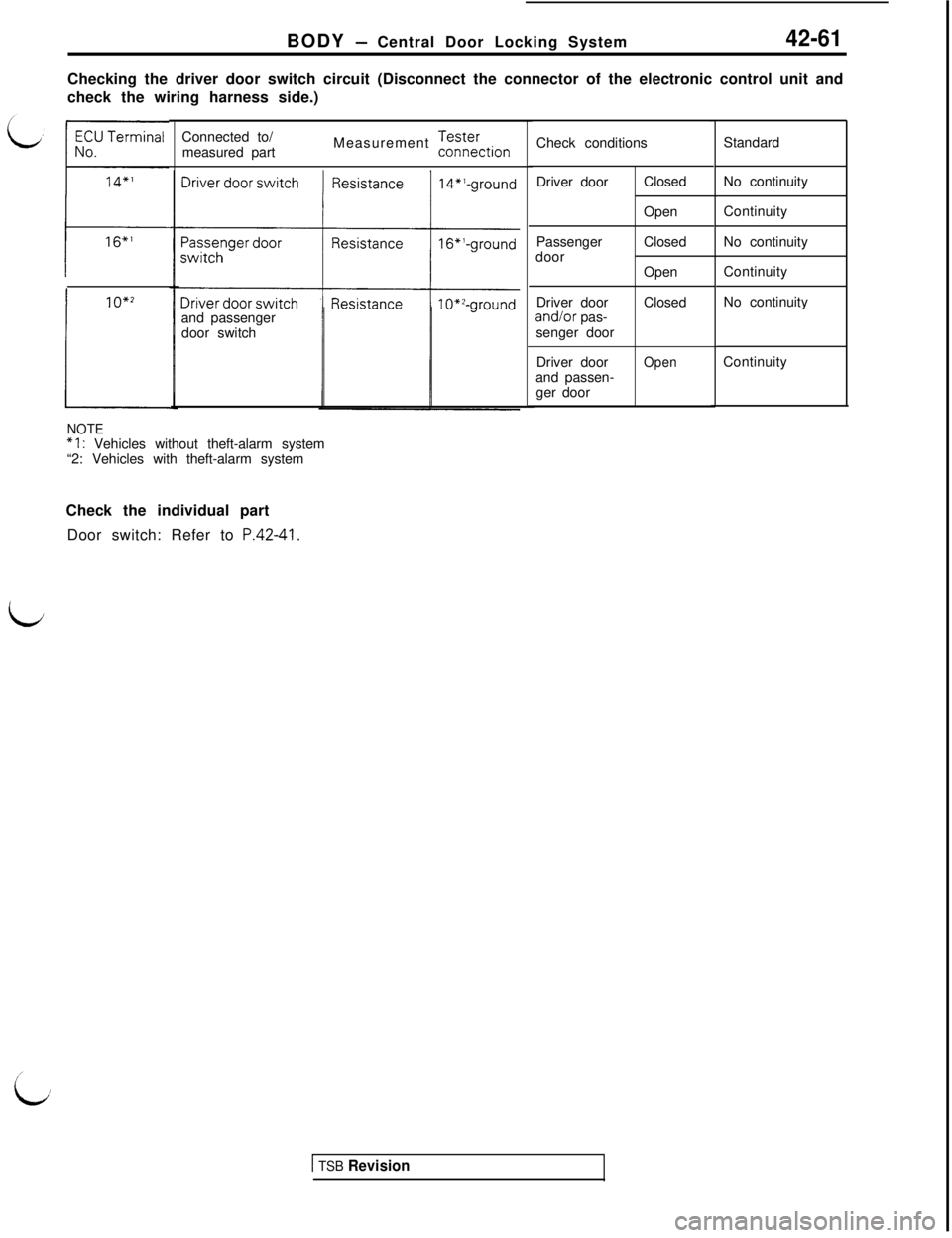
BODY - Central Door Locking System42-61Checking the driver door switch circuit (Disconnect the connector of the electronic control unit and
check the wiring harness side.)
and passenger
door switch
1O*2
i
NOTE“I : Vehicles without theft-alarm system
“2: Vehicles with theft-alarm systemConnected to/
measured partMeasurement -ff~~e~rionCheck conditionsStandard
Driver doorClosed
Open
Passenger
doorClosed
Open
Driver doorClosedand/or pas-
senger doorNo continuity
Continuity
No continuity
Continuity
No continuity
Driver door
Openand passen-
ger doorContinuity
Check the individual part
Door switch: Refer to
P.42-41.
id
1 TSB Revision
Page 934 of 1146
42-62BODY - Central Door Locking System
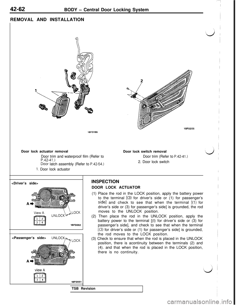
REMOVAL AND INSTALLATION16FO196
Door lock actuator removal
Door trim and waterproof film (Refer toP.42-41.)Do&
latch assembly (Refer to P.42-54.)
1. Door lock actuator
18FO205Door lock switch removal
Door trim (Refer to P.42-41.)
2. Door lock switch
view A16FOO51INSPECTION
DOOR LOCK ACTUATOR
(1) Place the rod in the LOCK position, apply the battery power
to the terminal
L(3) for driver’s side or (1) for passenger’s
side1 and check to see that when the terminal [(l) for
driver’s side or (3) for passenger’s side] is grounded, the rod
moves to the UNLOCK position.
(2) Then place the rod in the UNLOCK position, apply the
battery power to the terminal [(I) for driver’s side or (3) for
passenger’s side], and check to see that when the terminal
[(3) for driver’s side or (1) for passenger’s side] is grounded,
the rod moves to the LOCK position.
(3) Check to ensure that when the rod is placed in the UNLOCK
position, there is acontinuity between the terminals (2) and
(4). and that when the rod is placed in the LOCK position,
there is no continuity.
TSB Revision
Page 935 of 1146
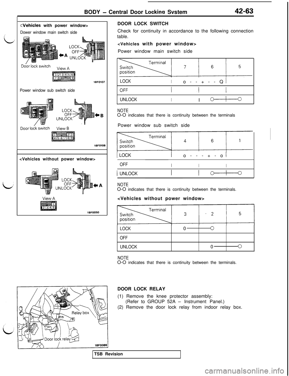
BODY - Central Door Lockina Svstem42-63
:Vehicles with power window>
Dower window main switch side
Power window sub switch side
18FO107
Check for continuity in accordance to the following connection
table.
Power window main switch side
LOCKIo--+--Q I
UNLOCKII c-+---oL
NOTEO-O indicates that there is continuity between the terminals
Power window sub switch side
1 LOCKIo---+-o I
OFFII
I
1 UNLOCKI c--+--
NOTEO-O indicates that there is continuity between the terminals.
LOCK00
OFF
UNLOCK00
NOTEO-O indicates that there is continuity between the terminals.
DOOR LOCK RELAY
(1) Remove the knee protector assembly:
(Refer to GROUP 52A
- Instrument Panel.)
(2) Remove the door lock relay from indoor relay box.
TSB Revision
Page 936 of 1146
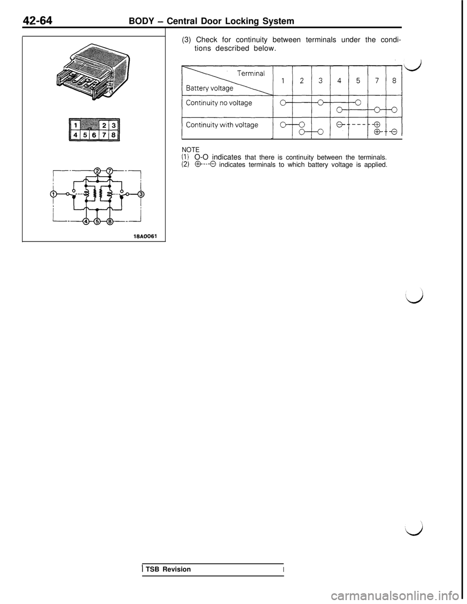
42-64BODY - Central Door Locking System
(3) Check for continuity between terminals under the condi-
tions described below.
I.IIIIII
NOTE(I )O-O indicates that there is continuity between the terminals.(2)O---O indicates terminals to which battery voltage is applied.
1 TSB RevisionI
Page 937 of 1146
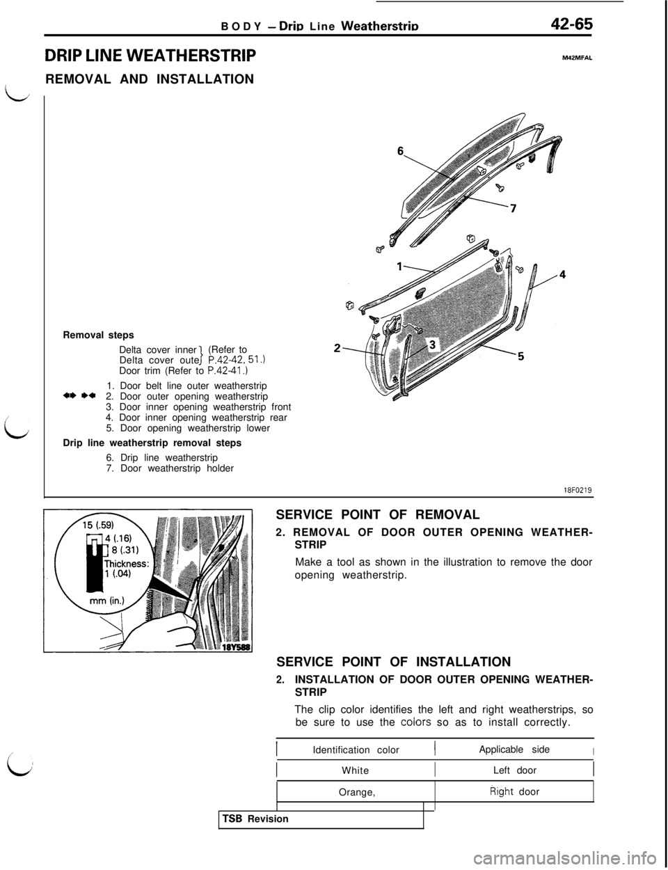
BODY - Drir, Line Weatherstrir,42-65
DRIP LINE WEATHERSTRIPM42MFALREMOVAL AND INSTALLATION
/
L
iRemoval steps
Delta cover inner
Delta cover outer P.42-42.51.)
1(Refer to
Door trim (Refer to P.4241.)
1. Door belt line outer weatherstrip
*I) I)+2. Door outer opening weatherstrip
3. Door inner opening weatherstrip front
4. Door inner opening weatherstrip rear
5. Door opening weatherstrip lower
Drip line weatherstrip removal steps
6. Drip line weatherstrip
7. Door weatherstrip holder
2-18FO219
SERVICE POINT OF REMOVAL
2. REMOVAL OF DOOR OUTER OPENING WEATHER-
STRIP
Make a tool as shown in the illustration to remove the door
opening weatherstrip.
SERVICE POINT OF INSTALLATION
2.INSTALLATION OF DOOR OUTER OPENING WEATHER-
STRIP
The clip color identifies the left and right weatherstrips, so
be sure to use the coiors so as to install correctly.
IIdentification colorIApplicable sideIWhiteLeft door
TSB RevisionOrange,Right door
Page 938 of 1146
Page 939 of 1146
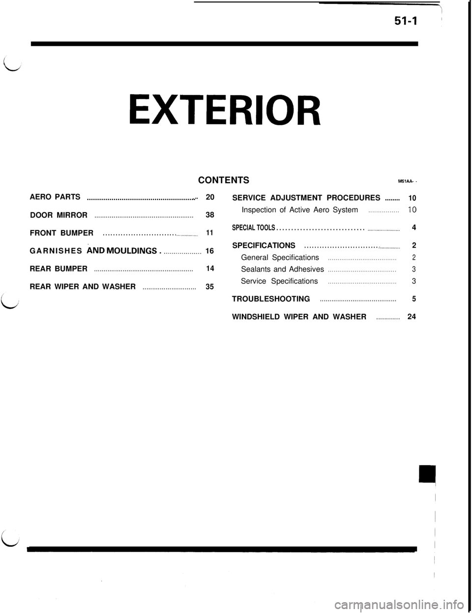
EXTERIORCONTENTS
MSIAA- -AERO PARTS
........................................................20
SERVICE ADJUSTMENT PROCEDURES........
10DOOR MIRROR
. . . . . . . . . . . . . . . . . . . . . . . . . . . . . . . . . . . . . . . . . . . . . . . . . . . .38Inspection of Active Aero System. . . . . . . . . . . . . . . .10FRONT BUMPER
. . . . . . . . . . . . . . . . . . . . . . . . . . . . . ..__...............11SPECIAL TOOLS . . . . . . . . . . . . . . . . . . . . . . . . . . . . . . ..__............_._...4
GARNISHES
AND MOULDINGS . ..__............... 16
REAR BUMPER
. . . . . . . . . . . . . . . . . . . . . . . . . . . . . . . . . . . . . . . . . . . . . . . . . . . .14SPECIFICATIONS
. . . . . . . . . . . . . . . . . . . . . . . . . . . . . . .._...............2General Specifications
. . . . . . . . . . . . . . . . . . . . . . . . . . . . . . . . . . . .2Sealants and Adhesives
. . . . . . . . . . . . . . . . . . . . . . . . . . . . . . . . . . . .3REAR WIPER AND WASHER
. . . . . . . . . . . . . . . . . . . . . . . . . . . .35Service Specifications. . . . . . . . . . . . . . . . . . . . . . . . . . . . . . . . . . . .3TROUBLESHOOTING
. . . . . . . . . . . . . . . . . . . . . . . . . . . . . . . . . . . . . . . .5WINDSHIELD WIPER AND WASHER
. . . . . . . . . . . .24
Page 940 of 1146
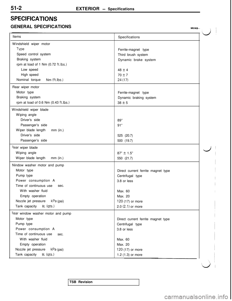
51-2
SPECIFICATIONSEXTERIOR
- Specifications
GENERAL SPECIFICATIONSMSlKB-
-\ IItems
Windshield wiper motorType
Speed control system
Braking system
rpm at load of 1 Nm (0.72
ft.lbs.)Low speed
High speed
Nominal torque
Nm (ft.lbs.)
Rear wiper motor
Motor type
Braking system
rpm at load of 0.6 Nm (0.43
ft.lbs.)Windshield wiper blade
Wiping angle
Driver’s side
Passenger’s side
Wiper blade length
mm (in.)
Driver’s side
Passenger’s side
Tear wiper blade
Wiping angle
Wiper blade lengthmm (in.)
Nindow washer motor and pump
Motor type
Pump type
Power consumption A
Time of continuous usesec.
With washer fluid
Empty operation
Nozzle jet pressure
kPa (psi)
Tank capacity
lit.
(qts.)
3ear window washer motor and pump
Motor type
Pump type
Power consumption A
Time of continuous use
sec.With washer fluid
Empty operation
Nozzle jet pressure
kPa (psi)
Tank capacity
lit. (qts.)Specifications
Ferrite-magnet type
Third brush system
Dynamic brake system
48
_+ 4
70
2 724(17)
Ferrite-magnet type
Dynamic braking system
38
+ 5
89”
91”
525 (20.7)
500 (19.7)87”
k 1.5”
550 (21.7)Direct current ferrite magnet type
Centrifugal type
3.8 or less
Max. 60
Max. 20
120 (17) or more
2.0
(2.1) or more
Direct current ferrite magnet type
Centrifugal type
3.8 or less
Max. 60
Max. 20
120 (17) or more
1.2 (1.3) or more
LJ
L/iTSB Revision