MITSUBISHI 380 2005 Workshop Manual
380 2005
MITSUBISHI
MITSUBISHI
https://www.carmanualsonline.info/img/19/57086/w960_57086-0.png
MITSUBISHI 380 2005 Workshop Manual
Trending: headlights, start stop button, Centre console, bulbs, mirror, fuel tank capacity, Gauge
Page 1031 of 1500
CROSSMEMBER
POWER PLANT MOUNT32-14
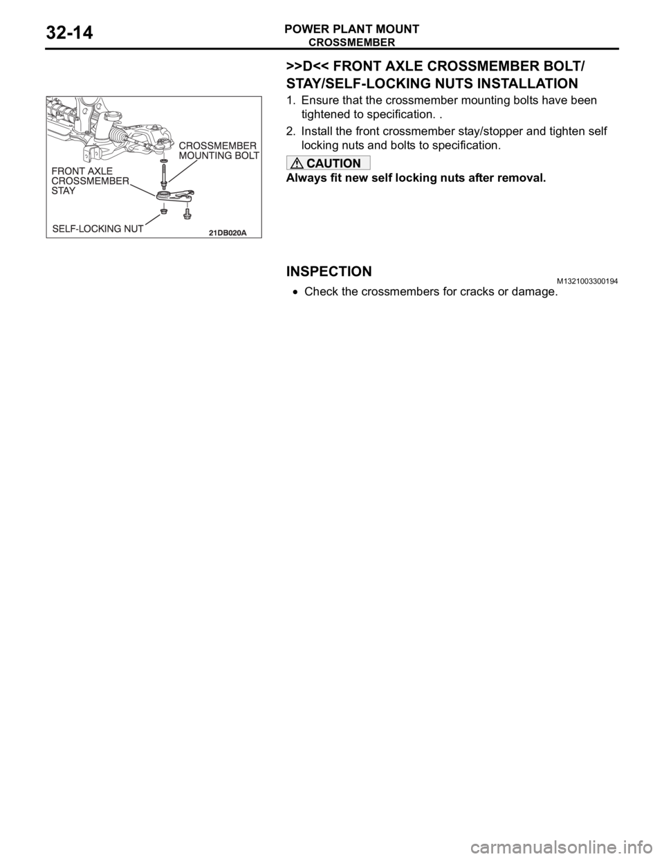
>>D<< FRONT AXLE CROSSMEMBER BOLT/
STAY/SELF-LOCKING NUTS INSTALLATION
1. Ensure that the crossmember mounting bolts have been
tightened to specification. .
2. Install the front crossmember stay/stopper and tighten self
locking nuts and bolts to specification.
Always fit new self locking nuts after removal.
INSPECTIONM1321003300194
Check the crossmembers for cracks or damage.
Page 1032 of 1500

SPECIFICATIONS
POWER PLANT MOUNT32-15
SPECIFICATIONS
FASTENER TIGHTENING SPECIFICATIONSM1321004100308
ITEM SPECIFICATION
Crossmember
Engine rear roll stopper bracket bolt 58
7 Nm
Front axle crossmember stay bolt and nut 83
12 Nm (61 9 ft-lb)
Front axle No.1 crossmember bolt and nut 180
20 Nm (133 15 ft-lb)
Lower arm assembly bolt 165
15 Nm (122 11 ft-lb)
Lower arm assembly nut (flange nut, self-locking) M14 165
15 Nm (122 11 ft-lb)
Lower arm ball joint clamp assembly nut 110
10 Nm
Power steering gear and linkage bolt 83
12 Nm (61 9 ft-lb)
Power steering gear bracket bolt M12 83
12 Nm (61 9 ft-lb)
Pressure hose clamp bolt and nut 12
2 Nm (102 22 in-lb)
Pressure hose nut 15
3 Nm (11 2 ft-lb)
Return tube clamp bolt and nut 12
2 Nm (102 22 in-lb)
Return tube nut 15
3 Nm (11 2 ft-lb)
Stabilizer bracket bolt 58
7 Nm (43 5 ft-lb)
Stabilizer link nut 48
7 Nm (36 5 ft-lb)
Steering column assembly bolt 18
2 Nm (13 2 ft-lb)
Steering gear and linkage protector bolt 12
2 Nm (102 22 in-lb)
Tie rod end nut 29
4 Nm (21 3 ft-lb)
Engine mounting
Engine mounting thru bolt M12 108
10 Nm (80 9 ft-lb)
Engine front mounting bracket bolt and nut M12 108
10 Nm (80 9 ft-lb)
Engine mounting stay bolt 36
6 Nm (27 4 ft-lb)
Engine roll stopper and centremember
Centremember bolt83
12 Nm (61 9 ft-lb)
Engine front roll stopper thru bolt and nut 69
10 Nm (61 9 ft-lb
Engine rear roll stopper thru bolt and nut 69
10 Nm (61 9 ft-lb
Transaxle case rear roll stopper bracket bolt 90
10 Nm (67 7 ft-lb)
Transaxle mounting
Transaxle mounting body side bracket nut (nut, flange) M12 83
12 Nm (61 9 ft-lb)
Transaxle mounting body side bracket nut (nut, self-locking) M1283
12 Nm (61 9 ft-lb)
Page 1033 of 1500
SPECIFICATIONS
POWER PLANT MOUNT32-16
Page 1034 of 1500
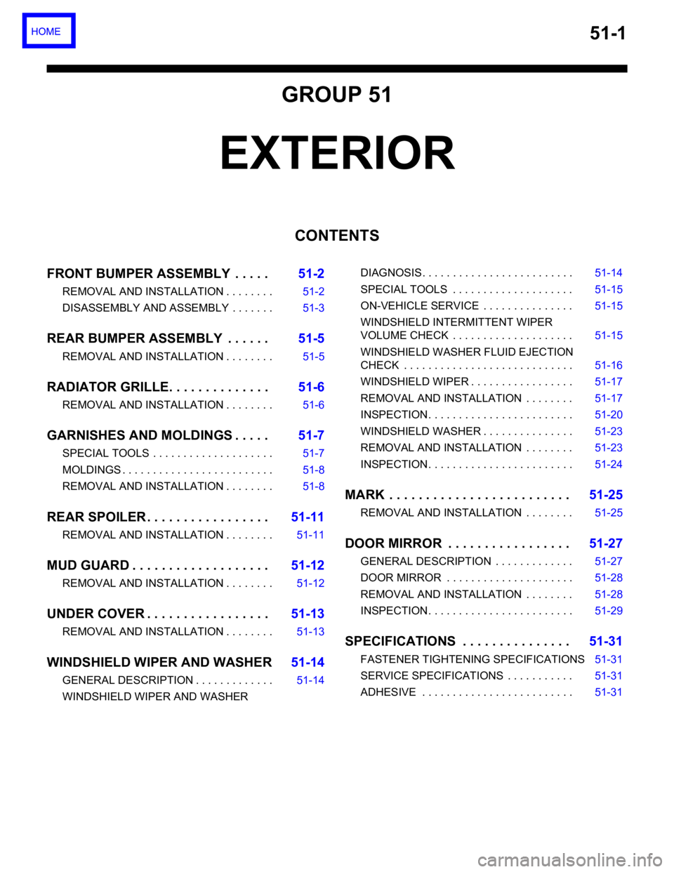
51-1
GROUP 51
EXTERIOR
CONTENTS
FRONT BUMPER ASSEMBLY . . . . .51-2
REMOVAL AND INSTALLATION . . . . . . . . 51-2
DISASSEMBLY AND ASSEMBLY . . . . . . . 51-3
REAR BUMPER ASSEMBLY . . . . . .51-5
REMOVAL AND INSTALLATION . . . . . . . . 51-5
RADIATOR GRILLE. . . . . . . . . . . . . .51-6
REMOVAL AND INSTALLATION . . . . . . . . 51-6
GARNISHES AND MOLDINGS . . . . .51-7
SPECIAL TOOLS . . . . . . . . . . . . . . . . . . . . 51-7
MOLDINGS . . . . . . . . . . . . . . . . . . . . . . . . . 51-8
REMOVAL AND INSTALLATION . . . . . . . . 51-8
REAR SPOILER . . . . . . . . . . . . . . . . .51-11
REMOVAL AND INSTALLATION . . . . . . . . 51-11
MUD GUARD . . . . . . . . . . . . . . . . . . .51-12
REMOVAL AND INSTALLATION . . . . . . . . 51-12
UNDER COVER . . . . . . . . . . . . . . . . .51-13
REMOVAL AND INSTALLATION . . . . . . . . 51-13
WINDSHIELD WIPER AND WASHER51-14
GENERAL DESCRIPTION . . . . . . . . . . . . . 51-14
WINDSHIELD WIPER AND WASHER DIAGNOSIS . . . . . . . . . . . . . . . . . . . . . . . . . 51-14
SPECIAL TOOLS . . . . . . . . . . . . . . . . . . . . 51-15
ON-VEHICLE SERVICE . . . . . . . . . . . . . . . 51-15
WINDSHIELD INTERMITTENT WIPER
VOLUME CHECK . . . . . . . . . . . . . . . . . . . . 51-15
WINDSHIELD WASHER FLUID EJECTION
CHECK . . . . . . . . . . . . . . . . . . . . . . . . . . . . 51-16
WINDSHIELD WIPER . . . . . . . . . . . . . . . . . 51-17
REMOVAL AND INSTALLATION . . . . . . . . 51-17
INSPECTION. . . . . . . . . . . . . . . . . . . . . . . . 51-20
WINDSHIELD WASHER . . . . . . . . . . . . . . . 51-23
REMOVAL AND INSTALLATION . . . . . . . . 51-23
INSPECTION. . . . . . . . . . . . . . . . . . . . . . . . 51-24
MARK . . . . . . . . . . . . . . . . . . . . . . . . .51-25
REMOVAL AND INSTALLATION . . . . . . . . 51-25
DOOR MIRROR . . . . . . . . . . . . . . . . .51-27
GENERAL DESCRIPTION . . . . . . . . . . . . . 51-27
DOOR MIRROR . . . . . . . . . . . . . . . . . . . . . 51-28
REMOVAL AND INSTALLATION . . . . . . . . 51-28
INSPECTION. . . . . . . . . . . . . . . . . . . . . . . . 51-29
SPECIFICATIONS . . . . . . . . . . . . . . .51-31
FASTENER TIGHTENING SPECIFICATIONS51-31
SERVICE SPECIFICATIONS . . . . . . . . . . . 51-31
ADHESIVE . . . . . . . . . . . . . . . . . . . . . . . . . 51-31
Page 1035 of 1500
FRONT BUMPER ASSEMBLY
EXTERIOR51-2
FRONT BUMPER ASSEMBLY
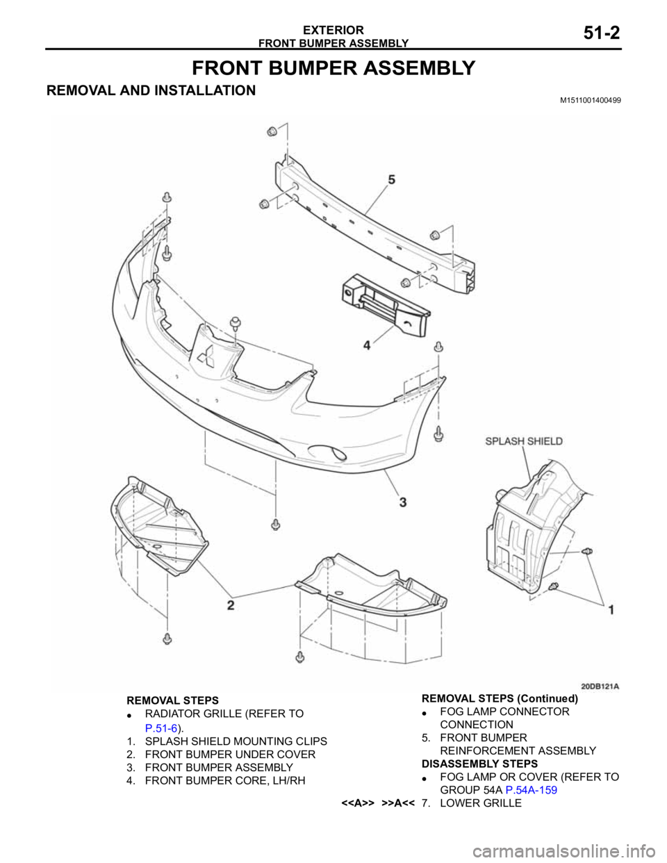
REMOVAL AND INSTALLATIONM1511001400499
REMOVAL STEPS
RADIATOR GRILLE (REFER TO
P.51-6).
1. SPLASH SHIELD MOUNTING CLIPS
2. FRONT BUMPER UNDER COVER
3. FRONT BUMPER ASSEMBLY
4. FRONT BUMPER CORE, LH/RHFOG LAMP CONNECTOR
CONNECTION
5. FRONT BUMPER
REINFORCEMENT ASSEMBLY
DISASSEMBLY STEPS
FOG LAMP OR COVER (REFER TO
GROUP 54A P.54A-159
<> >>A<<7. LOWER GRILLE REMOVAL STEPS (Continued)
Page 1036 of 1500
Page 1037 of 1500
FRONT BUMPER ASSEMBLY
EXTERIOR51-4
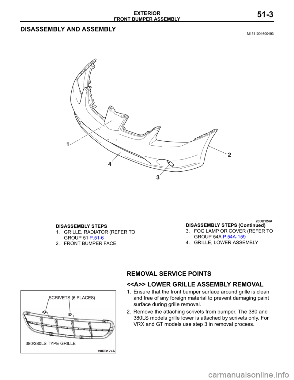
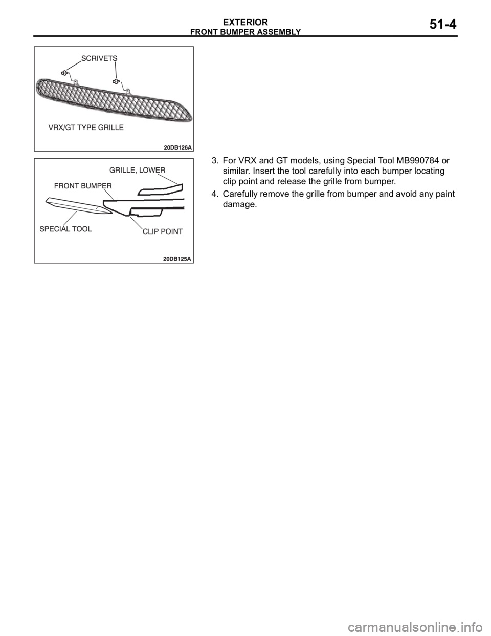
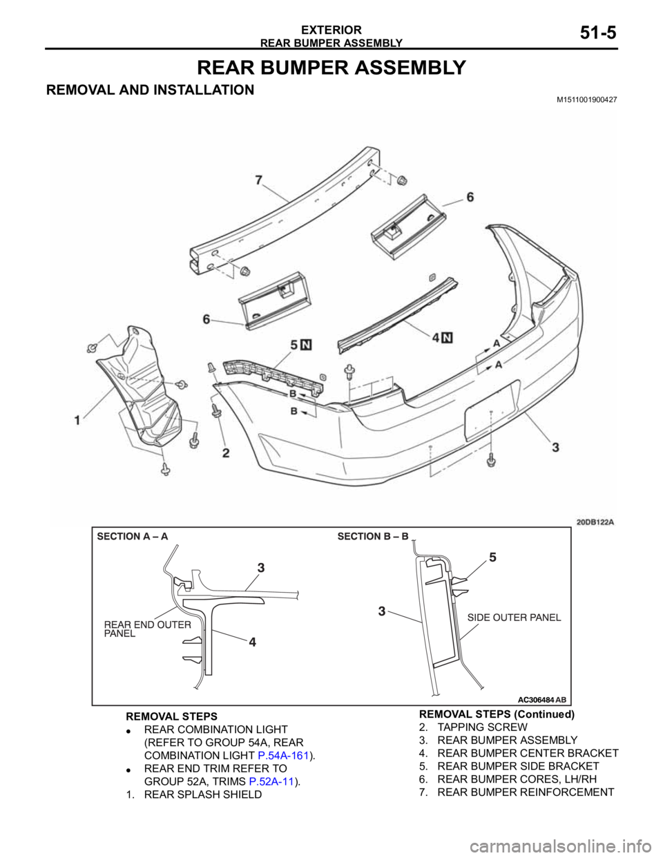
3. For VRX and GT models, using Special Tool MB990784 or
similar. Insert the tool carefully into each bumper locating
clip point and release the grille from bumper.
4. Carefully remove the grille from bumper and avoid any paint
damage.
Page 1038 of 1500
REAR BUMPER ASSEMBLY
EXTERIOR51-5
REAR BUMPER ASSEMBLY
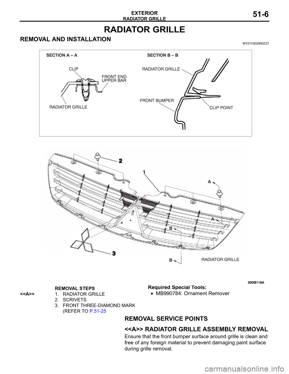
REMOVAL AND INSTALLATIONM1511001900427
REMOVAL STEPS
REAR COMBINATION LIGHT
(REFER TO GROUP 54A, REAR
COMBINATION LIGHT P.54A-161).
REAR END TRIM REFER TO
GROUP 52A, TRIMS P.52A-11).
1. REAR SPLASH SHIELD2. TAPPING SCREW
3. REAR BUMPER ASSEMBLY
4. REAR BUMPER CENTER BRACKET
5. REAR BUMPER SIDE BRACKET
6. REAR BUMPER CORES, LH/RH
7. REAR BUMPER REINFORCEMENT REMOVAL STEPS (Continued)
Page 1039 of 1500
Page 1040 of 1500
GARNISHES AND MOLDINGS
EXTERIOR51-7
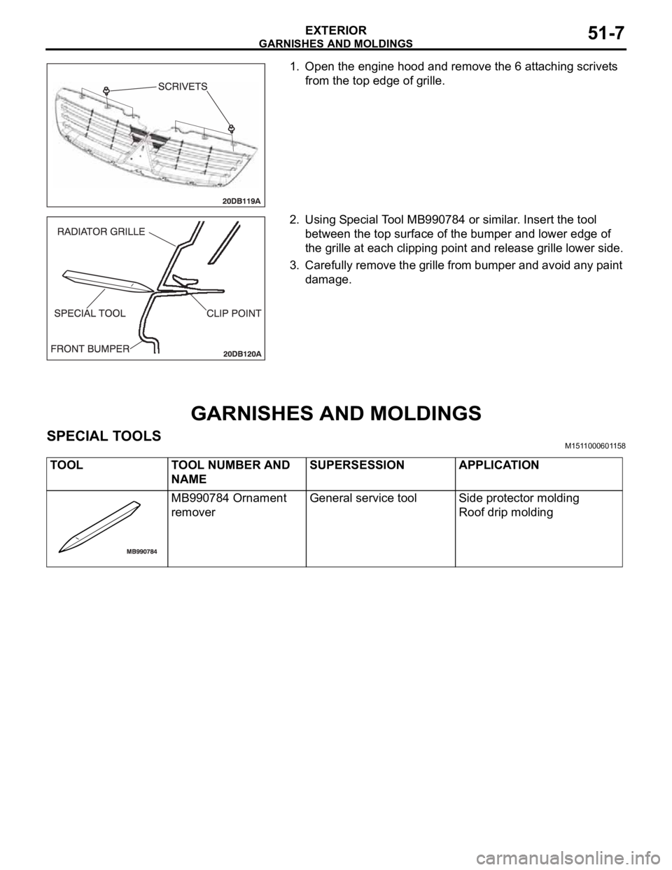
1. Open the engine hood and remove the 6 attaching scrivets
from the top edge of grille.
2. Using Special Tool MB990784 or similar. Insert the tool
between the top surface of the bumper and lower edge of
the grille at each clipping point and release grille lower side.
3. Carefully remove the grille from bumper and avoid any paint
damage.
GARNISHES AND MOLDINGS
SPECIAL TOOLSM1511000601158
TOOL TOOL NUMBER AND
NAMESUPERSESSION APPLICATION
MB990784 Ornament
removerGeneral service tool Side protector molding
Roof drip molding
Trending: Trunk lock, height, seats, air condition, Sound system, Plug, air conditioning
