MITSUBISHI DIAMANTE 1900 Repair Manual
Manufacturer: MITSUBISHI, Model Year: 1900, Model line: DIAMANTE, Model: MITSUBISHI DIAMANTE 1900Pages: 408, PDF Size: 71.03 MB
Page 361 of 408
BRAKES 9-25
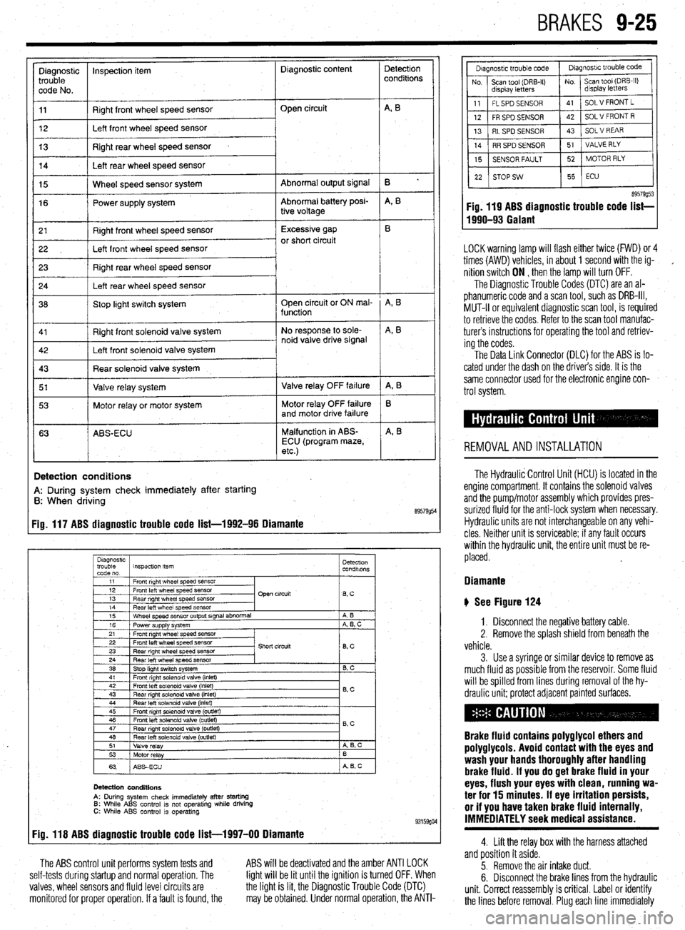
Diagnostic inspection item Diagnostic content
trouble
code No.
11 Right front wheel speed sensor
12 Left front wheel speed sensor Open circuit
13 Right rear wheel speed sensor
14 Left rear wheel speed sensor
Abnormal output signal
Abnormal battery posi-
tive voltage 15 Wheel speed sensor system
16 Power supply system
r 21
I Right front wheel speed sensor 1 Excessive gap
22 I Left front wheel speed sensor or short circuit
23 Right rear wheel speed sensor
24 Left rear wheel speed sensor
36 Stop light switch system Open circuit or ON mal-
function
Right front solenoid valve system
I 5’ I Valve relay system 1 Valve relay OFF failure
I 53 1 Motor relay or motor system Motor relay OFF failure
and motor drive failure
63 ABS-ECU Malfunction in ABS-
ECU (program maze,
etc.)
I
!
Detection
conditions
B ’
A, B
A, B
A, B
A, 8
B
A, B
Detection conditions
A: During system check immediately after starting
B: When driving
89579954 Fig. 117 ABS diagnostic trouble code list-1992-96 Diamante
Diagnostrc
trouble Inspection item Detectron
code no. condalons
1
11 1 Front right wheel speed SensOr
I
I I
12 1 Front left wheel speed sensor
13 1 Rear right wheel speed sensor Open circuit
lBsC I
14
Rear left wheel speed sensor
15 Wheel speed sensor output signal abnormal
16 Power supply system
21 Front right wheel speed sensor A B
A, B, C
22 Front left wheel speed sensor
23 Rear right wheel speed sensor
24 Rear left wheel speed sensor
38 Stop light switch system Short circuit
8, c
B. C
41 1 Front right solenoid valve (inlet)
I I
42
Front left solenoid valve (inlet)
43 Rear right solenord valve (inlet) 0.c
44 Rear left solenoid valve (inlet)
45 Front right solenoid valve (outlet)
46 Front left solenoid valve (outlet)
47
Rear nght solenoid valve (outret) - B,C
48 Rear left solenoid valve (outlet)
51
Valve relay A 6, c
53
Motor relay B
63 ABSECU A B, c
Detection conditions
A: During system check immediately after starting 6: While ABS control is not operating while driving C: While ABS control is operating 93159go4 Fig. 118 ABS diagnostic trouble code list-1997-00 Diamante
The ABS control unit performs system tests and
self-tests during startup and normal operation. The
valves, wheel sensors and fluid level circuits are
monitored for proper operation. If a fault is found, the ABS will be deactivated and the amber ANTI LOCK
light will be lit until the ignition is turned OFF. When
the light is lit, the Diagnostic Trouble Code (DTC)
may be obtained. Under normal operation, the ANTI-
89579g53 Fig. 119 ABS diagnostic trouble code list-
1990-93 Galant
LOCK warning lamp will flash either twice (FWD) or 4
times (AWD) vehicles, in about 1 second with the ig-
,
nition switch ON , then the lamp will turn OFF.
The Diagnostic Trouble Codes (DTC) are an al-
phanumeric code and a scan tool, such as DRB-III,
MUT-II or equivalent diagnostic scan tool, is required
to retrieve the codes. Refer to the scan tool manufac-
turers instructions for operating the tool and retriev-
ing the codes.
The Data Link Connector (DLC) for the ABS is lo-
cated under the dash on the driver’s side. It is the
same connector used for the electronic engine con-
trol system.
REMOVALANDINSTALLATION
The Hydraulic Control Unit (HCU) is located in the
engine compartment. It contains the solenoid valves
and the pump/motor assembly which provides pres-
surized fluid for the anti-lock system when necessary.
Hydraulic units are not interchangeable on any vehi-
cles Neither unit is serviceable; if any fault occurs
within the hydraulic unit, the entire unit must be re-
placed.
Diamante
b See Figure 124
1. Disconnect the negative battery cable.
2. Remove the splash shield from beneath the
vehicle.
3. Use a syringe or similar device to remove as
much fluid as possible from the reservoir. Some fluid
will be spilled from lines during removal of the hy-
draulic unit; protect adjacent painted surfaces.
Brake fluid contains polyglycol ethers and
poly9lycols. Avoid contact with the eyes and
wash your hands thoroughly after handling
brake fluid. If you do 9et brake fluid in your
eyes, flush your eyes with clean, running wa-
ter for 15 minutes. If eye irritation persists,
or if you have taken brake fluid internally,
IMMEDIATELY seek medical assistance.
4. Lift the relay box with the harness attached
and position it aside.
5. Remove the air intake duct.
6. Disconnect the brake lines from the hydraulic
unit. Correct reassembly is critical. Label or identify
the lines before removal. Plug each line immediately
Page 362 of 408
Diagnostic InspeclM item
trouble
code no. Detection
conditions
11 Front right wheel speed sensor
12 Front left wheel speed sensor
13 Rear right wheel speed sensor Open circuit
6 c
14
Rear left wheel speed sensor
16
Power supply system
21 Front right wheel speed sensor
22 Front left wheel speed sensor Short circuit 4 0. C
0, c
23
Rear right wheel speed sensof
24 Rear left wheel speed sensor
25 Front right wheel speed sensor
26 Front left wheel speed sensor Excessive gap
B, c
27 / Rear right wheel speed sensor
26 1 Rear left wheel speed sew
33
Stop light switch system
35 Front right wheel speed sensor
36 Front left wheel speed sensor
37 Rear right wheel speed sensor Pulse orocessina
pheei speed in&t
corresponding to a
vehicle speed of 300
46 Rear left solenoid valve (outside)
51
Valve relay
52 Vti relay
53
Motor relay
54
Motor relay ON impossible ,
A B. C
OFF impossrble
A
ON impossible
B
OFF impossible
B, c
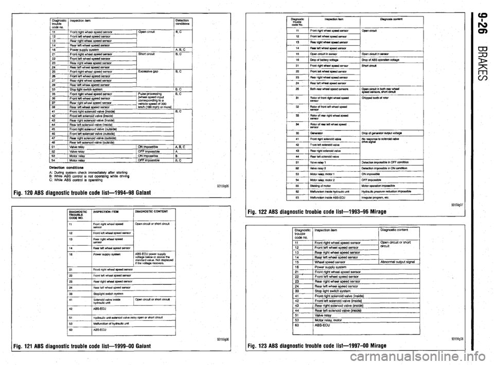
Detection conditions A: During system check immediately after starting
8: While ABS control is not operating while driving
C: While ABS control is operating
Fig. 120 ABS diagnostic trouble code list-1994-98 Galant 93159go5
DIAGNOSTIC INSPECTION IT’EH DIAGNOSTIC CONTENT
TROUBLE
CODE NO.
11 Front right wheel speed
Sensor Open circuit or short circuit
12
13 Front left wheel speed sensor
Rear right wheel speed
SBnsor
14
16 Fear left wheel speed ssnsor
Power supply system ABS-ECU power supply
voltage below or above the
standard value. Not displayed
if the voltage recovers.
21 Front right wheel speed sensor
22 Front left wheel speed sensor
23 Rear right whesl sped sensor
~
Hydraulic unit aolenoid valve relay open or short circuit
93159906
Fig. 121 ABS diagnostic trouble code list-1999-00 Galant Fig. 122 ABS diagnostic trouble code list-1993-96 Mirage
Page 363 of 408
BRAKES 9-27
93159g17
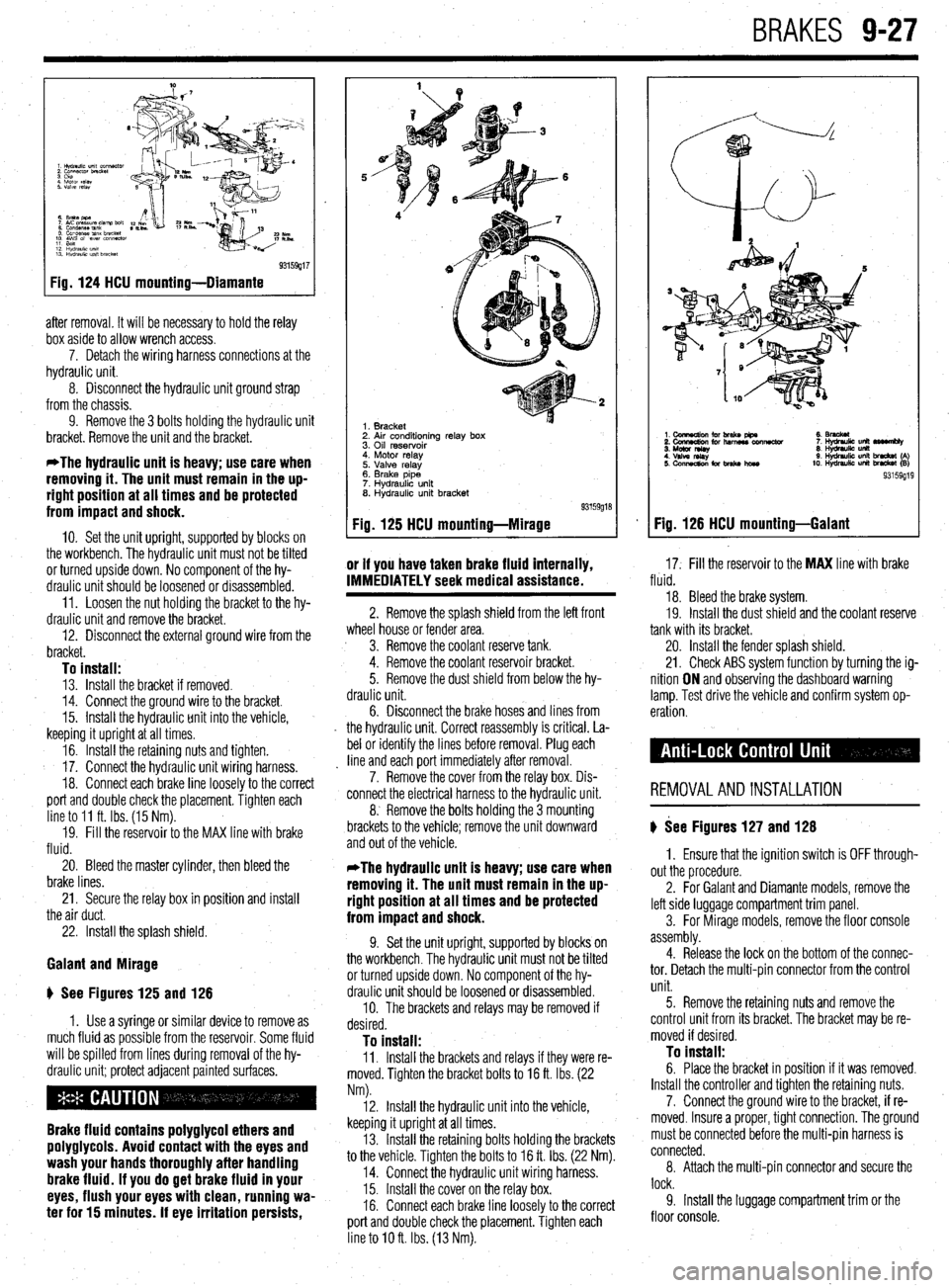
Fig. 124 HCU mounting-Diamante
after removal. It will be necessary to hold the relay
box aside to allow wrench access.
7. Detach the wiring harness connections at the
hydraulic unit.
8. Disconnect the hydraulic unit ground strap
from the chassis.
9. Remove the 3 bolts holding the hydraulic unit
bracket. Remove the unit and the bracket.
*The hydraulic unit is heavy; use care when
removing it. The unit must remain in the up-
right position at all times and be protected
from impact and shock.
IO. Set the unit upright, supported by blocks on
the workbench. The hydraulic unit must not be tilted
or turned upside down. No component of the hy-
draulic unit should be loosened or disassembled.
11. Loosen the nut holding the bracket to the hy-
draulic unit and remove the bracket.
12. Disconnect the external ground wire from the
bracket.
To install: 13. Install the bracket if removed.
14. Connect the ground wire to the bracket.
15. Install the hydraulic unit into the vehicle,
keeping it upright at all times.
16. Install the retaining nuts and tighten.
17. Connect the hydraulic unit wiring harness.
18. Connect each brake line loosely to the correct
port and double check the placement. Tighten each
line to 11 ft. Ibs. (15 Nm).
19. Fill the reservoir to the MAX line with brake
fluid.
20. Bleed the master cylinder, then bleed the
brake lines.
21. Secure the relay box in position and install
the air duct.
22. Install the splash shield.
Galant and Mirage
ti See Figures 125 and 126
1. Use a syringe or similar device to remove as
much fluid as possible from the reservoir. Some fluid
will be spilled from lines during removal of the hy-
draulic unit; protect adjacent painted surfaces.
Brake fluid contains polyglycol ethers and
polyglycols. Avoid contact with the eyes and
wash your hands thoroughly after handling
brake fluid. If you do get brake fluid in your
eyes, flush your eyes with clean, running wa-
ter for 15 minutes. If eye irritation persists,
1. Bracket
2. Air conditioning relay box
3. Oil reservoir
4. Motor relay
5. Valve relay
6. Brake pipe
7. Hydraulic unit
8. Hydraulic unit bracket
Fig. 125 HCU mounting-Mirage
or if you have taken brake fluid internally,
17. Fill the reservoir to the MAX line with brake IMMEDIATELY seek medical assistance. fluid.
2. Remove the splash shield from the left front
wheel house or fender area.
3. Remove the coolant reserve tank.
4. Remove the coolant reservoir bracket.
5. Remove the dust shield from below the hy-
draulic unit.
6. Disconnect the
brake hoses and lines from
the hydraulic unit. Correct reassembly is critical. La-
bel or identify the lines before removal. Plug each
line and each port immediately after removal.
7. Remove the cover from the relay box. Dis-
connect the electrical harness to the hydraulic unit.
8. Remove the bolts holding the 3 mounting
brackets to the vehicle; remove the unit downward
and out of the vehicle. 18. Bleed the brake system.
19. Install the dust shield and the coolant reserve
tank with its bracket.
20. Install the fender splash shield.
21. Check ABS system function by turning the ig-
nition ON and observing the dashboard warning
lamp. Test drive the vehicle and confirm system op-
eration.
REMOVALANDINSTALLATION
) See Figures 127 and 128
*The hydraulic unit is heavy; use care when
removing it. The unit must remain in the up-
right position at all times and be protected
from impact and shock.
9. Set the unit upright, supported by blocks on
the workbench. The hydraulic unit must not be tilted
or turned upside down. No component of the hy-
draulic unit should be loosened or disassembled.
10. The brackets and relays may be removed if
desired.
To install: 11. Install the brackets and relays if they were re-
moved. Tighten the bracket bolts to 16 ft. Ibs. (22
Nm). 1. Ensure that the ignition switch is OFF through-
out the procedure.
2. For Galant and Diamante models, remove the
left side luggage compartment trim panel.
3. For Mirage models, remove the floor console
assembly.
4. Release the lock on the bottom of the connec-
tor. Detach the multi-pin connector from the control
unit.
12. Install the hydraulic unit into the vehicle,
keeping it upright at all times.
13. Install the retaining bolts holding the brackets
to the vehicle. Tighten the bolts to 16 ft. Ibs. (22 Nm).
14. Connect the hydraulic unit wiring harness.
15. Install the cover on the relay box.
16. Connect each brake line loosely to the correct
port and double check the placement. Tighten each
line to IO ft. Ibs. (13 Nm). 5. Remove the retaining nuts and remove the
control unit from its bracket. The bracket may be re-
moved if desired. To install: 6. Place the bracket in position if it was removed.
Install the controller and tighten the retaining nuts.
7. Connect the ground wire to the bracket, if re-
moved. Insure a proper, tight connection. The ground
must be connected before the multi-pin harness is
connected.
8. Attach the multi-pin connector and secure the
lock.
9. Install the luggage compartment trim or the
floor console.
Fig. 126 HCU mounting-Galant
Page 364 of 408
9-28 BRAKES
1. Electronic control una
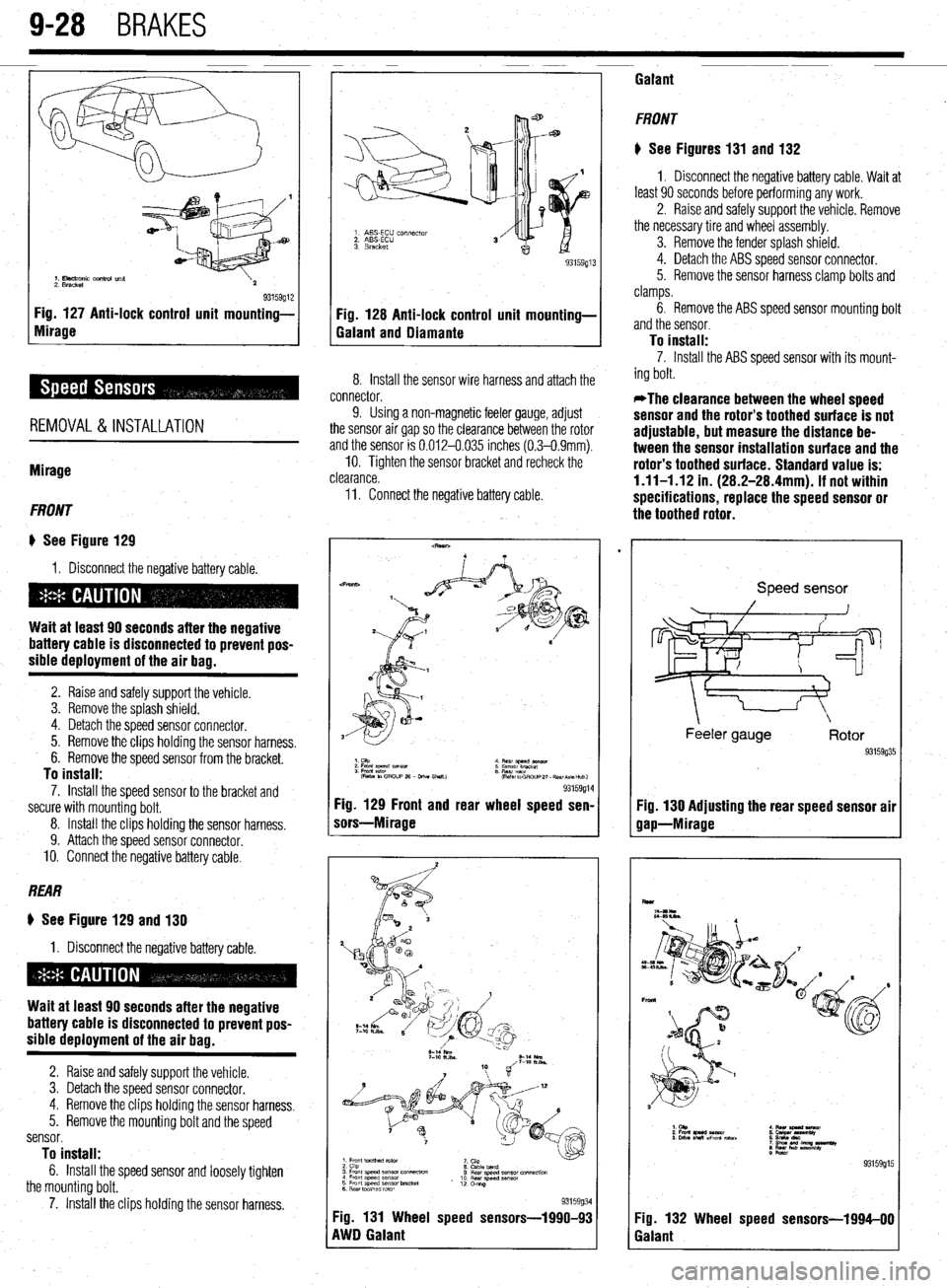
2. Bracket 93159912 Fig. 127 Anti-lock control unit mounting-
Fig. 128 Anti-lock control unit mounting-
Mirage
Galant and Diamante
REMOVAL&INSTALLATION
Mirage
FRONT
I) See Figure 129
1, Disconnect the negative battery cable.
Wait at least 90 seconds after the negative
battery cable is disconnected to prevent pos-
sible deployment of the air bag.
2. Raise and safely support the vehicle.
3. Remove the splash shield.
4. Detach the speed sensor connector.
5. Remove the clips holding the sensor harness.
6. Remove the speed sensor from the bracket.
To install: 7. Install the speed sensor to the bracket and
secure with mounting bolt.
8. Install the clips holding the sensor harness.
9. Attach the speed sensor connector.
IO. Connect the negative battery cable.
REAR
8 See Figure 129 and 130
1. Disconnect the negative battery cable.
Wait at least 90 seconds after the negative
battery cable is disconnected to prevent pos-
sible deployment of the air bag.
2. Raise and safely support the vehicle.
3. Detach the speed sensor connector.
4. Remove the clips holding the sensor harness.
5. Remove the mounting bolt and the speed
sensor.
To install: 6. Install the speed sensor and loosely tighten
the mounting bolt,
7. Install the clips holding the sensor harness.
1. ABS-ECU ccr~nector
2. ABSECU
3. Bracket
8. Install the sensor wire harness and attach the
connector,
9. Using a non-magnetic feeler gauge, adjust
the sensor air gap so the clearance between the rotor
and the sensor is 0.012-0.035 inches (0.3-0.9mm).
IO. Tighten the sensor bracket and recheck the
clearance.
11. Connect the negative battery cable.
Fig. 129 Front and rear wheel speed sen-
sors-Mirage
1
3. Front speed sensor connwxwn
4 Fmnt sweed sensor
5 Front speed sensor bracket
6 Rear toothed rotor 8 Cabletand
8 Rear speed sensor connection
10 Rear speed sensx
12 omg
93159934 Fig. 131 Wheel speed sensors-1990-93
RWD Galant Galant
FRONT
# See Figures 131 and 132
1. Disconnect the negative battery cable. Wait at
least 90 seconds before performing any work.
2. Raise and safely support the vehicle. Remove
the necessary tire and wheel assembly.
3. Remove the fender splash shield.
4. Detach the ABS speed sensor connector.
5. Remove the sensor harness clamp bolts and
clamps.
6. Remove the ABS speed sensor mounting bolt
and the sensor.
To install: 7. Install the ABS speed sensor with its mount-
ing bolt.
*The clearance between the wheel speed
sensor and the rotor’s toothed surface is not
adjustable, but measure the distance be-
tween the sensor installation surface and the
rotor’s toothed surface. Standard value is:
1.11-1 .I2 in. (28.2-28.4mm). If not within
specifications, replace the speed sensor or
the toothed rotor.
Speed sensor
Feeler gauge
93159g35
Fig. 130 Adjusting the rear speed sensor air
gap-Mirage
6
Fig. 132 Wheel speed sensors-1994-00
Galant
Page 365 of 408
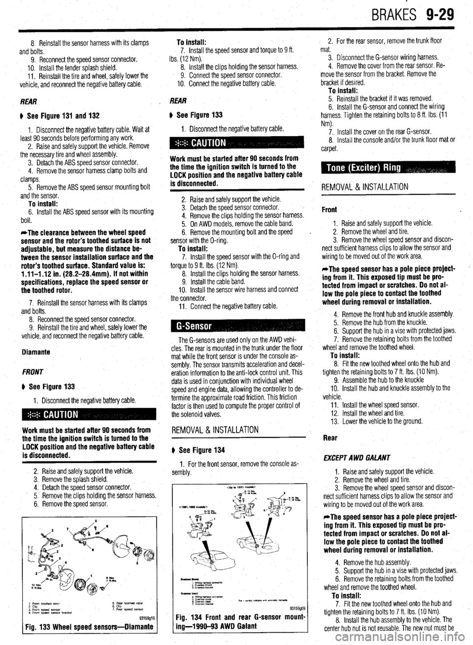
BRAKES 9-29
8. Reinstall the sensor harness with its clamps
and bolts.
9. Reconnect the speed sensor connector.
IO. Install the fender splash shield.
11. Reinstall the tire and wheel, safely lower the
vehicle, and reconnect the negative battery cable. To install: 7. Install the speed sensor and torque to 9 ft.
Ibs. (12 Nm).
8. Install the clips holding the sensor harness.
9. Connect the speed sensor connector.
IO. Connect the negative battery cable.
REAR REAR
) See Figure 131 and 132
1. Disconnect the negative battery cable. Wait at
least 90 seconds before performing any work.
2. Raise and safely support the vehicle. Remove
the necessary tire and wheel assembly.
3. Detach the ABS speed sensor connector.
4. Remove the sensor harness clamp bolts and
clamps.
I) See Figure 133
1. Disconnect the negative battery cable.
5. Remove the ABS speed sensor mounting bolt
and the sensor.
Work must be started after 90 seconds from
the time the ignition switch is turned to the
LOCK position and the negative battery cable
is disconnected.
To install:
6. Install the ABS speed sensor with its mounting
bolt.
*The clearance between the wheel speed
sensor and the rotor’s toothed surface is not
adjustable, but measure the distance be-
tween the sensor installation surface and the
rotor’s toothed surface. Standard value is:
1.11-l .I2 in. (28.2-28.4mm). If not within
specifications, replace the speed sensor or
the toothed rotor.
2. Raise and safely support the vehicle.
3. Detach the speed sensor connector.
4. Remove the clips holding the sensor harness.
5. On AWD models, remove the cable band.
6. Remove the mounting bolt and the speed
sensor with the O-ring.
To install: 7. Install the speed sensor with the O-ring and
torque to 9 ft. Ibs. (12 Nm).
8. Install the clips holding the sensor harness.
9. Install the cable band.
10. Install the sensor wire harness and connect
the connector.
7. Reinstall the sensor harness with its clamps
and bolts.
8. Reconnect the speed sensor connector.
9. Reinstall the tire and wheel, safely lower the
vehicle, and reconnect the negative battery cable.
Diamante
FRONT
* See Figure 133
1. Disconnect the negative battery cable.
Work must be started after 90 seconds from
the time the ignition switch is turned to the
LOCK position and the negative battery cable
is disconnected.
2. Raise and safely support the vehicle.
3. Remove the splash shield.
4. Detach the speed sensor connector.
5. Remove the clips holding the sensor harness.
6. Remove the speed sensor.
1 Front toothed rotor
2 Ckp
3 Front speed sensor
4 Front speed aenmr bracket t ;5’ toothed rotor ‘I Rear speed SB"SO,
93159016
Fig. 133 Wheel speed sensors-Diamante
11. Connect the negative battery cable.
The G-sensors are used only on the AWD vehi-
cles. The rear is mounted in the trunk under the floor
mat while the front sensor is under the console as-
sembly. The sensor transmits acceleration and decel-
eration information to the anti-lock control unit. This
data is used in conjunction with individual wheel
speed and engine data, allowing the controller to de-
termine the approximate road friction. This friction
factor is then used to compute the proper control of
the solenoid valves.
REMOVAL&INSTALLATION
# See Figure 134
1. For the front sensor, remove the console as-
sembly.
-lkol*)
1 wimp--vx
2 Gasnan I‘m”0
3. Gmwor LmcM
Bmar burl
: wwzh&T&m~mm-
6 G.smsol Ired Th, - ape.24 m-5 un Nt- vmsa*.
7 c-.elwnbRcta
93159909 Fig. 134 Front and rear G-sensor mount-
ing-l 990-93 AWD Galant
2. For the rear sensor, remove the trunk floor
mat.
3. Disconnect the G-sensor wiring harness.
4. Remove the cover from the rear sensor. Re-
move the sensor from the bracket. Remove the
bracket if desired.
To install: 5. Reinstall the bracket if it was removed.
6. Install the G-sensor and connect the wiring
harness. Tighten the retaining bolts to 8 ft. Ibs. (11
Nm).
7. Install the cover on the rear G-sensor.
8, Install the console and/or the trunk floor mat or
carpet.
REMOVAL & INSTALLATION
Front
1. Raise and safely support the vehicle.
2. Remove the wheel and tire.
3. Remove the wheel speed sensor and discon-
nect sufficient harness clips to allow the sensor and
wiring to be moved out of the work area.
*The speed sensor has a pole piece project-
ing from it. This exposed tip must be pro-
tected from impact or scratches. Do not al-
low the pole piece to contact the toothed
wheel during removal or installation.
4. Remove the front hub and knuckle assembly.
5. Remove the hub from the knuckle.
6. Support the hub in a vise with protected jaws.
7. Remove the retaining bolts from the toothed
wheel and remove the toothed wheel.
To install: 8. Fit the new toothed wheel onto the hub and
tighten the retaining bolts to 7 ft. Ibs. (10 Nm).
9. Assemble the hub to the knuckle
IO. Install the hub and knuckle assembly to the
vehicle.
11. Install the wheel speed sensor.
12. Install the wheel and tire.
13. Lower the vehicle to the ground.
Rear
EXCEPT AWD GALANT
1. Raise and safely support the vehicle.
2. Remove the wheel and tire.
3. Remove the wheel speed sensor and discon-
nect sufficient harness clips to allow the sensor and
wiring to be moved out of the work area.
*The speed sensor has a pole piece project-
ing from it. This exposed tip must be pro-
tected from impact or scratches. Do not al-
low the pole piece to contact the toothed
wheel during removal or installation.
4. Remove the hub assembly.
5. Support the hub in a vise with protected jaws.
6. Remove the retaining bolts from the toothed
wheel and remove the toothed wheel.
To install: 7. Fit the new toothed wheel onto the hub and
tighten the retaining bolts to 7 ft. Ibs. (10 Nm).
8. Install the hub assembly to the vehicle. The
center hub nut is not reusable. The new nut must be
Page 366 of 408
9-30 BRAKES
tightened to 144-188 ft. Ibs. (200-260 Nm). After the
nut is tightened, align the nut with the spindle inden-
tation and crimp the nut in place.
9. Install the wheel speed sensor.
10. Install the wheel and tire.
11. Lower the vehicle to the ground.
AWD GALANT
1. Raise and safely support the vehicle.
2. Remove the wheel and tire.
3. Disconnect the parking brake cable from the
caliper.
4. Remove the speed sensor and its O-ring.
Disconnect sufficient clamps and wire ties to allow
the sensor to be moved well out of the work area.
*The speed sensor has a pole piece project-
ing from it. This exposed tip must be pro-
tected from impact or scratches. Do not al-
low the pole piece to contact the toothed
wheel during removal or installatlon.
5. Remove the brake caliper and brake disc.
6. Remove the 3 retaining nuts and bolts hold-
ing the outer end of the driveshaft to the companion
flange.
7. Swing the axle shaft away and support it with
stiff wire. Do not overextend the joint in the axle; do
not allow it to hang unsupported.
, 8. Remove the retaining nut and washer on the
back of the driveshaft. Use special tool MB 9967 or
equivalent to counterhold the hub.
9. Remove the companion flange from the
knuckle.
IO. Using an axle puller which bolts to the wheel
lugs, remove the axle shaft assembly.
11. Fit the shaft assembly in a press with the
toothed wheel completely supported by a bearing
plate such as special tool MB 9e60 or its equivalent.
12. Press the toothed wheel off the axle shaft.
To install: 13. Press the new toothed wheel onto the shaft
with the groove facing the axle shaft flange. 14. Install the axle shaft to the knuckle and fit the
companion flange in place.
15. Install the lock washer and a new self-lock-
ing nut on the axle shaft. Tighten the nut to 116-159
ft. Ibs. (160-220 Nm).
16. Swing the axle assembly into place and in-
stall the 3 nuts and bolts. Tighten each to 45 ft. Ibs.
(61 Nm).
17. Install the brake disc and caliper.
18. Install the wheel speed sensor. Always use a
new O-ring.
19. Connect the parking brake cable to the
caliper.
20. Install the wheel and tire; lower the vehicle to
the ground.
There is no special procedure to bleed the ABS
system. Proceed with the normal brake bleeding pro-
cedure located earlier in this section.
Page 367 of 408
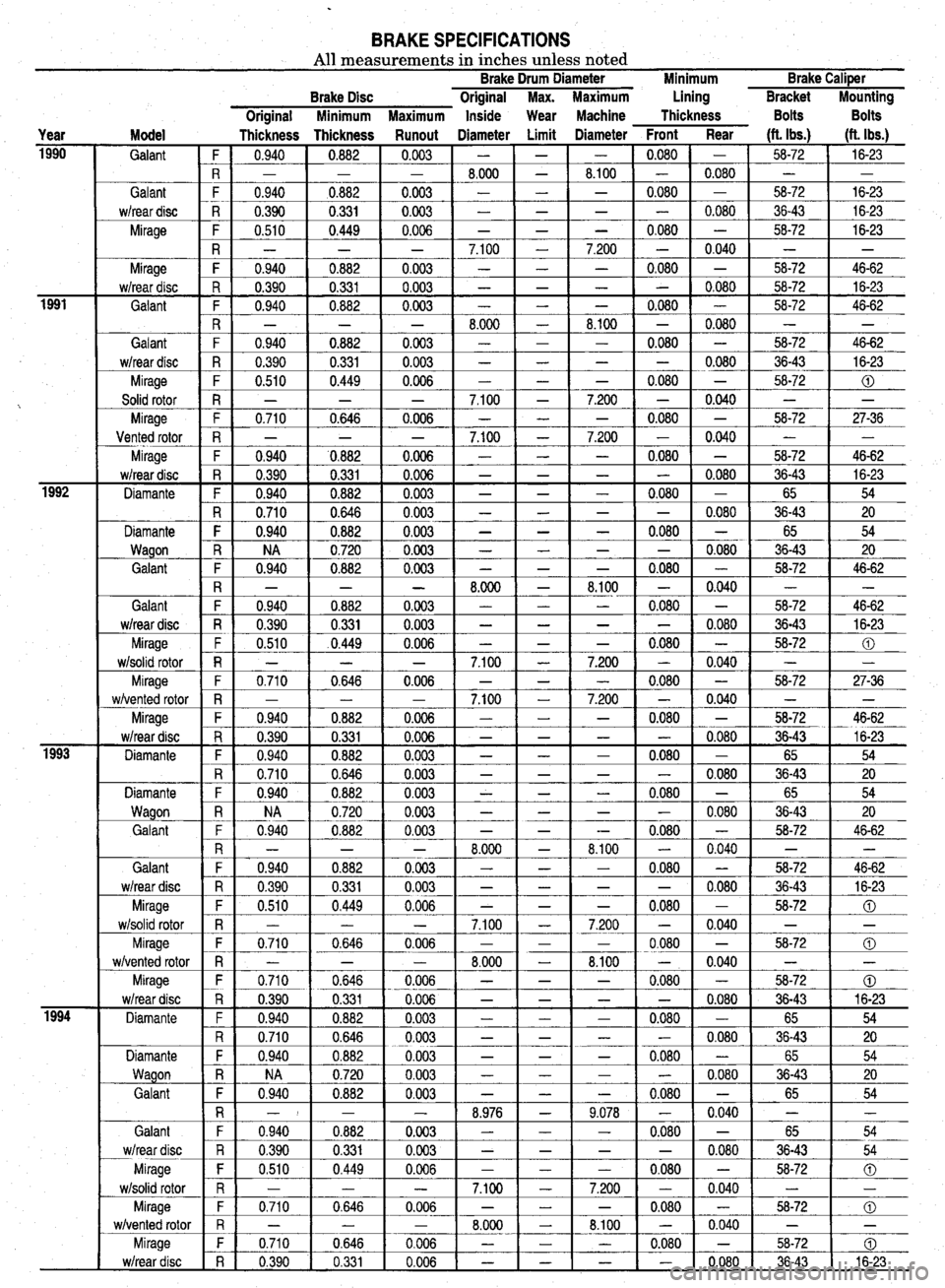
BRAKE SPECIFICATIONS All measurements in inches unless noted Brake Drum Diameter Minimum Brake CaliPer
Year Model
1990
Galant ~
Galant
w/rear disc
Mirage
1991
:
iiz- Mirage
w/rear disc
Galant
Galant
w/rear disc
Mirage
Solid rotor
Mirage
Vented rotor
Mirage
w/rear disc
Diamante
Diamante
Wagon
Galant
1993 Galant
w/rear disc
Mirage
w/solid rotor
Mirage
w/vented rotor
Mirage
w/rear disc
Diamante
Diamante
Wagon
Galant
im- Galant
w/rear disc
Mirage
w/solid rotor
Mirage
w/vented rotor
Mirage
w/rear disc
Diamante
Diamante
Wagon
Galant
Galant
w/rear disc
Mirage
w/solid rotor
Mirage
w/vented rotor
Mirage
w/rear disc Brake Disc Original Max. Maximum Lining Bracket
Miunting
Original Minimum Maximum Inside Wear Machine Thickness Bolts Bolts
Thickness Thickness Runout Diameter Limit Diameter Front Rear (ft. Ibs.)
(ft. Ibs.)
F 0.940
0.882 0.003 - - - 0.080 - 58-72
16-23
R - - - 8.000
- 8.100 - 0.080 - -
F 0.940
aO.882 0.003 - - - 0.080 - 58-72
16-23
R 0.390 0.331 0.003 -
- - - 0.080 36-43 16-23
F 0.510
0.449 0.006 - - - 0.080 - 58-72
16-23
R
- - - 7.100 - 7.200 - 0.040
- -
F 0.940 0.882 0.003 -
- - 0.080 - 58-72 46-62
R 0.390 0.331 0.003 -
- - - 0.080 58-72 16-23
F 0.940
0.882 0.003 - - - 0.080 - 58-72
46-62
R
_ - - 8.000 - 8.100 - 0.080
- -
F 0.940 0.882 0.003 -
- - 0.080 - 58-72 46-62
R 0.390 0.331 0.003 -
- - - 0.080 36-43 16-23
F 0.510
0.449 0.006 - - - 0.080 - 58-72
0
R - - - 7.100
- 7.200 - 0.040 - -
F 0.710 0.646 0.006 -
- - 0.080 - 58-72 27-36
R - - - 7.100
- 7.200 - 0.040 - -
F 0.940
'0.882 0.006 - - - 0.080 - 58-72
46-62
R 0.390
0.331 0.006 - - - - 0.080 36-43
16-23
F 0.940 0.882 0.003 -
- - 0.080 - 65 54
R 0.710
0.646 0.003 - - - - 0.080 36-43
20
F 0.940 0.882 0.003 -
- - 0.080 - 65 54
R
NA 0.720 0.003 - - - - 0.080
36-43 20
F 0.940 0.882 0.003 -
- - 0.080 - 58-72 46-62
R
- _ - 8.000 - 8.100 - 0.040
- -
F 0.940
0.882 0,003 - - - 0.080 -
58-72 46-62
R 0.390
0.331 0.003 - - - - 0.080
36-43 16-23
F 0.510
.0.449 0.006 - - - 0.080 -
58-72 0
R - - - 7.100
- 7.200 - 0.040 - -
F 0.710
0.646 0.006 - - - 0.080 -
58-72 27-36
R - - - 7.100
- 7.200 - 0.040 - -
F 0.940 0.882 0.006 -
- - 0.080 - 58-72 46-62
R 0.390
0.331 0.006 - - - - 0.080
36-43 16-23
F 0.940 0.882 0.003 -
- - 0.080 - 65 54
R 0.710
0.646 0.003 - - - - 0.080
36-43 20
F 0.940
0.882 0.003 - - - 0.080 -
65 54
R
NA 0.720 0.003 - - - - 0.080
36-43 20
F 0.940 0.882 0.003 -
- -- 0.080 - 58-72 46-62
R
- - - 8.000 - 8.100 - 0.040
- -
F 0.940
0.882 0.003 - - - 0.080 -
58-72 46-62
R 0.390 0.331 0.003 -
- - - 0.080 36-43 16-23
F 0.510 0.449 0.006 -
- - 0.080 - 58-72 0
R _ _ - 7.100
- 7.200 - 0.040 - -
F 0.710
0.646 0.006 - - - 0.080 -
58-72 0
R
_ - - 8.000 - 8.100 - 0.040
- -
F 0.710
0.646 0.006 - - - 0.080 -
58-72 CD
R 0.390
0.331 0.006 - - - - 0.080
36-43 16-23
F
0.940 0.882 0.003 - - - 0.080 -
65 54
R 0.710 0.646 0.003 -
- - - 0.080 36-43 20
F 0.940 0.882 0.003 -
- - 0.080 - 65 54
R
NA 0.720 0.003 - - - - 0.080
36-43 20
F 0.940 0.882 0.003 -
- - 0.080 - 65 54
R -I - - 8.976
- 9.078 - 0.040 - -
F 0.940 0.882 0.003 -
- - 0.080 - 65 54
R
0.390 0.331 0.003 - - - - 0.080
36-43 54
F 0,510 0.449 0.006 -
- - 0.080 - 58-72 0
R
_ _ - 7.100 - 7.200 - 0.040
- -
F 0.710 0.646 0.006 -
- - 0.080 - 58-72 0
R
- - - 8.000 - 8.100 - 0.040
- -
F
0.710 0.646 0.006 - - - 0.080 -
58-72 0
R 0.390 0.331 0.006 -
- - - 0.080 36-43 16-23
Page 368 of 408
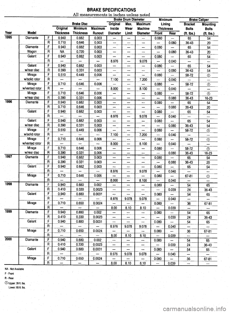
BRAKE SPECIFICATIONS All measurements in inches unless noted Brake Drum Diameter
Brake Disc Original Max. Maximum Minimum Brake Caliper
Lining
Bracket Mounting
Year
1995
1996
1997
isi-
1999
2ooo Original Minimum Maximum Inside
Wear Machine
Thickness Bolts
Bolts
Model
Thickness Thickness Runout Diameter Limit Diameter Front Rear Ht. Ibs.1
Diamante 1 (ft. Ibs.)
F 1 0.940 1 0.882 1 0.003 1 - 1 -
- 54 -
R 0.710 0.646 0.003 - -
Diamante F 0.940 0.882 0.003 - -
Wagon R NA 0.720 0.003 - -
Galant F 0.940 0.882 0.003 - - 0.080
-
0.080
-
-
0.080
-
--iizG-
-
0.040 ' I
65
36-43 20
65 54
36-43 20
65 54
- -
65 54
36-43 54
58-72 0
-
-
t- 0
-
.710 1 0.646 1 0.006 1 -
- 1 0.080 1
- 1 56-72 1 @
-
-
-
-
0.080 R - - - 8.976 -
Galant F 0.940 0.882 0.003 - -
wheardisc R 0.390 0.331 0.003 - -
Mirage F 0.510 0.449 0.006 - - 9.078
- -
0.080
- -
-
0.080
w/solid rotor
7.200
-
8.100 Mirage
w/vented rotor
Mirage
w/rear disc
Diam 1 R 1 0.390 1 0.331 1 0.006 I -
t--=-E5 1 -t-xii- 54
ante F 0.940 0.882 0.003 - - - 0.080 - 65
R 0.710 0.646 0.003 - - - - 0.080 36-43
20
Galant
Galant
wheardisc
Mirage
w/solid rotor
-
-
-
Mirage 1
wivente
d rotor -
‘ge
*disc 8.100 - 0.040 - -
- 0.080 -
58-72 0
- - 0.080 36-43 16-23 Mira - w/rear - -
Diamante F 0.940 0.882 0.003 - - - 0.080 -
65 54
R 0.390 0.331 0.003 - - - - 0.080
36-43 20
Galant F 0.940 0.882 0.003 - - -
0.l
380 - 65 54
R - - - 8.976 - 9.078 - 0.040 - -
Mirage F 0.710 0,646 0.006 - - -
0.l
380 - 67-81 0
PI
InI * n-a
- - - 1 LI.uuu 1 1 A #-A
- 8.1UU 1 - 0.040 - -
Diamante F 1 PPP- 0
t-t- R 0 ,940 0.880 0.002 - - - 0.080 - 54
65
,410 0.330 0.0023 - - - - _
0.039 24
36-43
snt 1 F I 0.940 0.880 0.0031 - - - 0.080 -
54 65 Gdi
Mirage
Diamante
Galant
R ' - _ - 8.976 9.078 9.078 -
0.040 L -
F 0.710 0.650 0.0024 - - - 0.080 - 36 67-81
R - - - 8.00 8.10 8.10 - 0.039 - -
F 0.940 0.880 0.002 - 1 - -
0.080 -
54 65
R 0
F 0
Mir;
Diamante
Galant I.410 0.330 0.0023 - -
1.940 0.880 0.0031 - -
- -
-
8.976 9.078
0.710 0.650 0.0024 - - - -
0.039
-
0.080 -
9,078 -
0.040
-
0.080 - 24
54
-
36 36-43
65
-
67-81
R - _ - 8.00 8.10 8.10 - 0.039 ii -
F 0.940 0.880 0.002 - - -
0.080 -
54 65
R 0.410 0.330 0.0023 - - - -
0.039 24 36-43
F 0.940
0.880 0.0031 - - - 0.080 - 54
65
R - - - 8.976 9.078 9.078 - 0.040 - -
we F 0.710 0.650 0.0024 - - - 0.080 - 36 Mirl _
i 1 1 1 1 1 . I 1 I I
R - - - 8.00 1 8.10 8.10 -
1 0.039
1 1 ,r -
1
NA - Not Available
F - Front
R - Rear
OUpper:39fLIbs. , Lower: 65 ft. Ibs.
Page 369 of 408
EXTERIOR IO-2
DOORS IO-2
REMOVAL&INSTALLATION IO-2
HOOD IO-2
REMOVAL&INSTALLATION IO-2
ALIGNMENT IO-3
HATCH IO-3
REMOVAL & INSTALLATION IO-3
ALIGNMENT IO-3
TAILGATE IO-3
REMOVAL & INSTALLATION IO-3
ALIGNMENT IO-3
TRUNK LID IO-3
REMOVAL &INSTALLATION IO-3
ALIGNMENT IO-3
OUTSIDE MIRRORS IO-3
REMOVAL &INSTALLATION IO-3
ANTENNA IO-4
REPLACEMENT IO-4
FENDERS IO-4
REMOVAL & INSTALLATION IO-4
INTERIOR 1
O-6 INSTRUMENTPANEL IO-6
REMOVAL & INSTALLATION IO-6
FLOOR CONSOLE IO-6
REMOVAL & INSTALLATION IO-6
DOOR PANELS IO-7
REMOVAL & INSTALLATION IO-7
DOORHANDLE/LATCHASSEMBLY IO-IO
REMOVAL &INSTALLATION IO-IO
DOOR LOCKCYLINDER IO-IO
REMOVAL &INSTALLATION IO-IO
HATCH/TAILGATE/TRUNKLID LOCK
CYLINDER IO-IO
REMOVAL &INSTALLATION IO-IO
TAILGATE/HATCH HANDLE IO-IO
REMOVAL &INSTALLATION IO-IO
DOORGLASSANDREGULATOR IO-IO
REMOVAL&INSTALLATION IO-IO
ELECTRIC WINDOW MOTOR IO-IO
REMOVAL &INSTALLATION IO-IO
INSIDE REAR VIEW MIRROR IO-IO
REPLACEMENT IO-IO
SEATS IO-IO
REMOVAL & INSTALLATION IO-IO
POWERSEATMOTOR IO-11
REMOVAL &INSTALLATION IO-11
SPECIFICATIONS CHART
TORQUE SPECIFICATIONS IO-14
4
Page 370 of 408
IO-2 BODYANDTRIM
6. Remove the hinge bolts and remove the door
assembly.
REMOVAL &INSTALLATION To install:
7. Position the door into place and finger
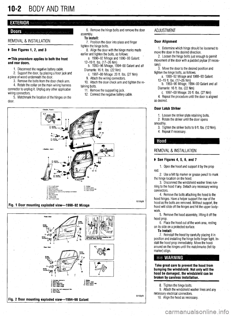
ti See Figures 1, 2, and 3
*This procedure applies to both the front
and rear doors.
1. Disconnect the negative battery cable.
2. Support the door, by placing a floor jack and
.a piece of wood underneath the door.
3. Remove the bolts from the door check arm.
4. Rotate the collar on the main wiring harness
connector to unplug it. Unplug any other applicable
wiring connectors.
5. Matchmark the location of the hinges on the
door. tighten the hinge bolts.
s 8. Align the door with the hinge marks made
earlier and tighten the bolts, as follows:
’
a. 1990-92 Mirage and 1990-93 Galant:
12-19 ft. Ibs. (6l7,26 Nm&
b. 1993-9 Mirage, 1 94-00 Galant and all
Diamante: 16 ft. Ibs. (22 Nm)
c. 1997-00 Mirage: 20 ft. Ibs. (27 Nm)
9. Attach the wiring connectors.
IO. Attach the door check arm and tighten the re-
taining bolts.
II. Remove the supporting jack.
12. Connect the negative battery cable.
Fig. 1 Door mounting exploded view-1990-92
Mirage 9315oQo8
9315oQog 1
Fig. 2 Door mounting ixploded view-1994-98 Galanf ADJUSTMENT
Door Alignment
1. Determine which hinge should be loosened to
move the door in the desired direction.
2. Loosen the hinge bolts just enough to permit
movement of the door with a padded prybar (if neces-
sary).
3. Move the door to the desired position and
tighten the hinge bolts, as follows:
a. 1990-92 Mirage and 1990-93 Galant:
12-19 ft. Ibs. ($7-26 Nmg
b. 1993-9 Mirage, 1 94-00 Galant and all
Diamante: 16 ft. Ibs. (22 Nm)
c. 1997-00 Mirage: 20 ft. Ibs. (27 Nm)
4. Repeat the procedure until the door is aligned
as desired.
Door Latch Striker
1. Loosen the striker plate retaining bolts.
2. Rotate the striker until the door opens
smoothly.
3. Tighten the striker
bolts to 9 ft. Ibs. (12 Nm).
4. Repeat if necessary.
REMOVAL & INSTALLATION
ti See Figures 4, 5, 6, and 7
1, Open the hood and support it by the prop
rod.
2. Use a felt tip marker or grease pencil to mark
the hinge location on the hood.
3. Disconnect the windshield washer lines run-
ning to the hood if any. Detach any necessary wiring
connectors.
4. Remove the bolts attaching the hood to the
hood hinges. Have a helper support the rear of the
hood as the bolts are removed. Without support, the
hood will slide off the hinges and hit the upper body-
work.
5. Remove the hood assembly, lifting it off the
hood prop.
6. Place the hood out of the work area, resting
on its side on a protected surface.
To install: 7. Reinstall the hood by carefully placing it in
position and instaliing the hinge bolts finger tight. In-
stall the hood prop immediately. Move the hood.
around on the hinges until the matchmarks (felt tip
marker) align.
Take great care to prevent the hood from
bumping the windshield. Not only will the
hood be damaged, the windshield can be
broken by careless installation.
8. Tighten the hinge bolts.
9. Attach the windshield washer lines and any
necessary electrical connectors. )
IO. Align the hood as necessary.