MITSUBISHI DIAMANTE 1900 Repair Manual
Manufacturer: MITSUBISHI, Model Year: 1900, Model line: DIAMANTE, Model: MITSUBISHI DIAMANTE 1900Pages: 408, PDF Size: 71.03 MB
Page 341 of 408
BRAKES 9-5
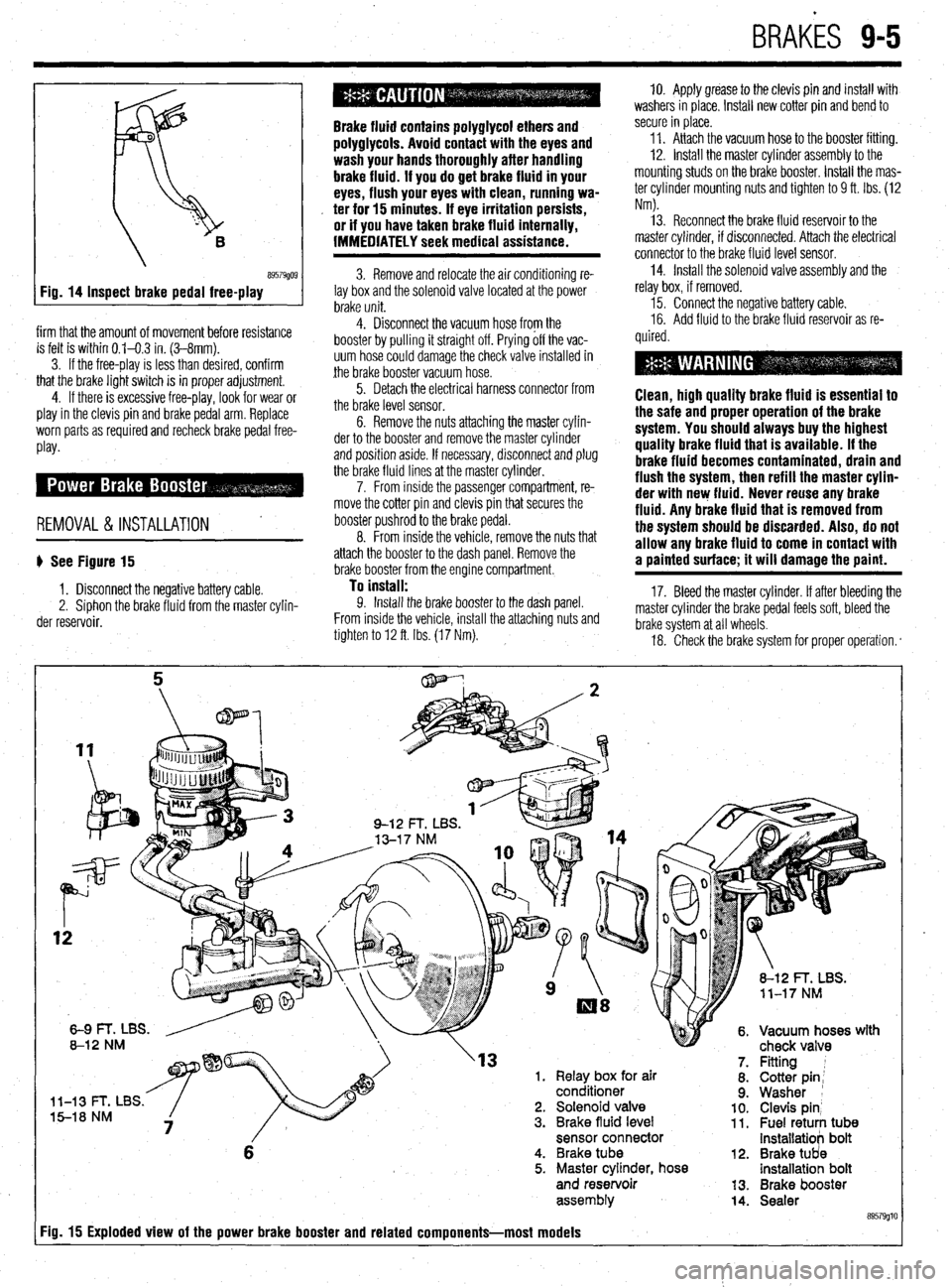
Inspect brake pedal free-play
firm that the amount of movement before resistance
is felt is within 0.1-0.3 in. (3-8mm).
3. If the free-play is less than desired, confirm
that the brake light switch is in proper adjustment.
4. If there is excessive free-play, look for wear or
play in the clevis pin and brake pedal arm. Replace
worn parts as required and recheck brake pedal free-
Play*
REMOVAL &INSTALLATION '
b See Figure 15
1. Disconnect the negative battery cable.
2. Siphon the brake fluid from the master cylin-
der reservoir.
Brake fluid contains polyglycol ethers and
polyglycols. Avoid contact with the eyes and
wash your hands thoroughly after handling
brake fluid. If you do get brake fluid in your
eyes, flush your eyes with clean, running wa-
. ter for 15 minutes. If eye irritation persists,
or if you have taken brake fluid internally,
IMMEDIATELY seek medical assistance.
3. Remove and relocate the air conditioning re-
lay box and the solenoid valve located at the power
brake unit.
4. Disconnect the vacuum hose from the
booster by pulling it straight off. Prying off the vac-
uum hose could damage the check valve installed in
the brake booster vacuum hose.
5. Detach the electrical harness connector from
the brake level sensor.
6. Remove the nuts attaching the master cylin-
der to the booster and remove the master cylinder
and position aside. If necessary, disconnect and plug
the brake fluid lines at the master cylinder.
7. From inside the passenger compartment, re-
move the cotter pin and clevis pin that secures the
booster pushrod to the brake pedal.
8. From inside the vehicle, remove the nuts that
attach the booster to the dash panel. Remove the
brake booster from the engine compartment.
To install: 9. Install the brake booster to the dash panel.
From inside the vehicle, install the attaching nuts and
tighten to 12 ft. Ibs. (17 Nm). 10. Apply grease to the clevis pin and install with
washers in place. Install new cotter pin and bend to
secure in place.
11. Attach the vacuum hose to the booster fitting.
12. Install the master cylinder assembly to the
mounting studs on the brake booster. Install the mas-
ter cylinder mounting nuts and tighten to 9 ft. Ibs. (12
Nm).
13. Reconnect the brake fluid reservoir to the
master cylinder, if disconnected. Attach the electrical
connector to the brake fluid level sensor.
14. Install the solenoid valve assembly and the
relay box, if removed.
15. Connect the negative battery cable.
16. Add fluid to the brake fluid reservoir as re-
quired.
Clean, high quality brake fluid is essentlal to
the safe and proper operation of the brake
system. You should always buy the highest
quality brake fluid that is available. If the
brake fluid becomes contaminated, drain and
flush the system, then refill the master cylin-
der with new fluid. Never reuse any brake
fluid. Any brake fluid that is removed from
the system should be discarded. Also, do not
allow any brake fluid to come in contact with
a painted surface; it will damage the paint.
17. Bleed the master cylinder. If after bleeding the
master cylinder the brake pedal feels soft, bleed the
brake system at all wheels.
18. Check the brake system for proper operation. *
rn( mr
'13 1. Relay box for air
conditioner
l-13 t- I, Ltx5. 5-18 NM 2. Solenoid valve
3. Brake fluid level
sensor connector
6 4. Brake tube
5. Master cylinder, hose
and reservoir
assem biy
Fig. 15 Exploded view of the power brake booster and related components-most models
12.
13.
14. Fitting 1
Cotter pin;
Washer 1
Clevis pin’ Fuel retuti tub8 installatiob bolt
Brake tUd8 installatioh bolt
Brake booster
Sealer
89579glt
Page 342 of 408
.
9-6 BRAKES
REMOVAL & INSTALLATION
I) See Figure 2
1. Disconnect the negative battery cable.
2. Locate the proportioning valve, usually below
the master cylinder.
3. Tag and disconnect the brake lines from the
valve.
Brake fluid contains poiygiycoi ethers and
poiygiycois. Avoid contact with the eyes and
wash your hands thoroughly after handling
brake fluid. if you do get brake fluid in your
eyes, flush your eyes with clean, running wa-
ter for 15 minutes. if eye irritation persists,
or if you have taken brake fluid internally,
IMMEDIATELY seek medical assistance.
4. Remove the proportioning valve from the en-
gine compartment.
To install:
5. The installation is the reverse of the removal
procedure. Bleed the brakes in the following order:
6. Diamante
a. Right rear caliper
b. Left front caliper
c. Left rear caliper
d. Right front caliper
7. Mirage and Gaiant
a. Left rear wheel cylinder or caliper
b. Right front cylinder
c. Right rear wheel cylinder or caliper
d. Left front caliper
8. Connect the negative battery cable and check
the brakes for proper operation.
Clean, high quality brake fluid is essential to
the safe and proper operation of the brake
system. You should always buy the highest
quality brake fluid that is available. if the
brake fluid becomes contaminated, drain and
flush the system, then refill the master cyiin-
der with new fluid. Never reuse any brake
fluid. Any brake fluid that is removed from
the system should be discarded. Also, do not
allow any brake fluid to come in contact with
a painted surface; it will damage the paint.
Metal lines and rubber brake hoses should be
checked frequently for leaks and external damage.
Metal lines are particularly prone to crushing and
kinking under the vehicle. Any such deformation can
restrict the proper flow of fluid and therefore impair
braking at the wheels. Rubber hoses should be
checked for cracking or scraping; such damage can
create a weak spot in the hose and it could fail under
pressure.
Any time the lines are removed or disconnected,
extreme cleanliness must be observed. Clean all
joints and connections before disassembly (use a stiff bristle brush and clean brake fluid); be sure to
plug the lines and ports as soon as they are opened.
New lines and hoses should be flushed clean with
brake fluid before installation to remove any contami-
nation. REMOVAL&INSTALLATION
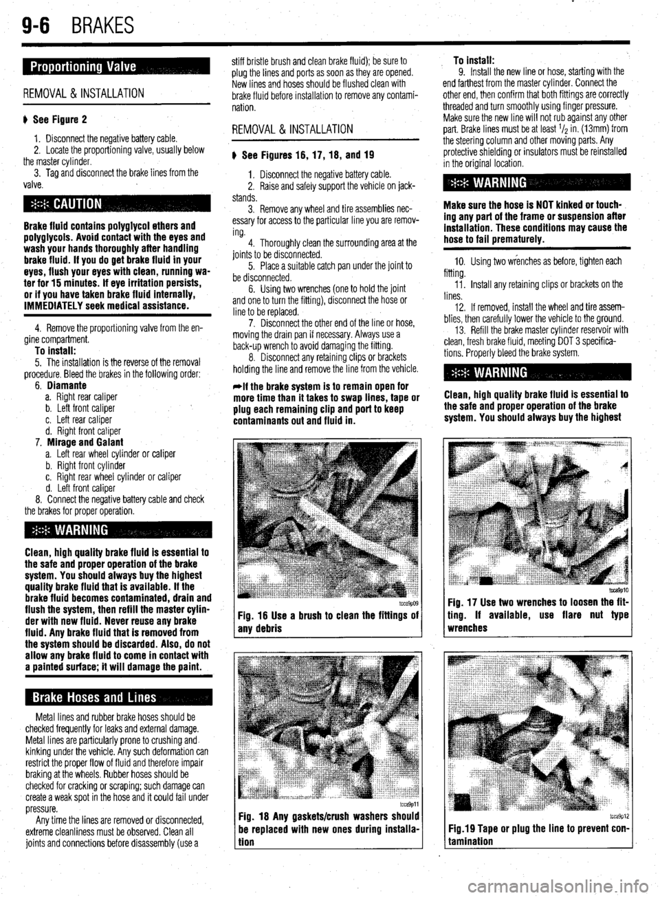
) See Figures 16, 17, 18, and 19
1. Disconnect the negative battery cable.
2. Raise and safely support the vehicle on jack-
stands.
3. Remove any wheel and tire assemblies nec-
essary for access to the particular line you are remov-
ing.
4. Thoroughly clean the surrounding area at the
joints to be disconnected.
5. Place a suitable catch pan under the joint to
be disconnected.
6. Using two wrenches (one to hold the joint
and one to turn the fitting), disconnect the hose or
line to be replaced.
7. Disconnect the other end of the line or hose,
moving the drain pan if necessary. Always use a
back-up wrench to avoid damaging the fitting.
8. Disconnect any retaining clips or brackets
holding the line and remove the line from the vehicle.
-if the brake system is to remain open for
more time than it takes to swap lines, tape or
plug each remaining clip and port to keep
contaminants out and fluid in.
I tcca9p09 tcca9p09 Fig. 16 Use a brush to clean the fittings of Fig. 16 Use a brush to clean the fittings of
any debris any debris
tcca9pll Fig. 18 Any gaskets/crush washers should
be replaced with new ones during instaiia-
tion To install:
9. Install the new line or hose, starting with the
end farthest from the master cylinder. Connect the
other end, then confirm that both fittings are correctly
threaded and turn smoothly using finger pressure.
Make sure the new line will not rub against any other
part. Brake lines must be at least l/z in. (13mm) from
the steering column and other moving parts. Any
protective shielding or insulators must be reinstalled
in the original location.
Make sure the hose is NOT kinked or touch-
ing any part of the frame or suspension after
installation. These conditions may cause the
hose to fail prematurely.
10. Using two wrenches as before, tighten each
fitting.
Ii. Install any retaining clips or brackets on the
lines.
12. If removed, install the wheel and tire assem-
blies, then carefully lower the vehicle to the ground.
13. Refill the brake master cylinder reservoir with
clean, fresh brake fluid, meeting DOT 3 specifica-
tions. Properly bleed the brake system.
Clean, high quality brake fluid is essential to
the safe and proper operation of the brake
system. You should always buy the highest
tcca9p10 Fig. 17 Use two wrenches to loosen the fit-
ting. If available, use flare nut type
wrenches
tcca9p12 Fig.19 Tape or plug the line to prevent con-
tamination
Page 343 of 408
BRAKES 9-7
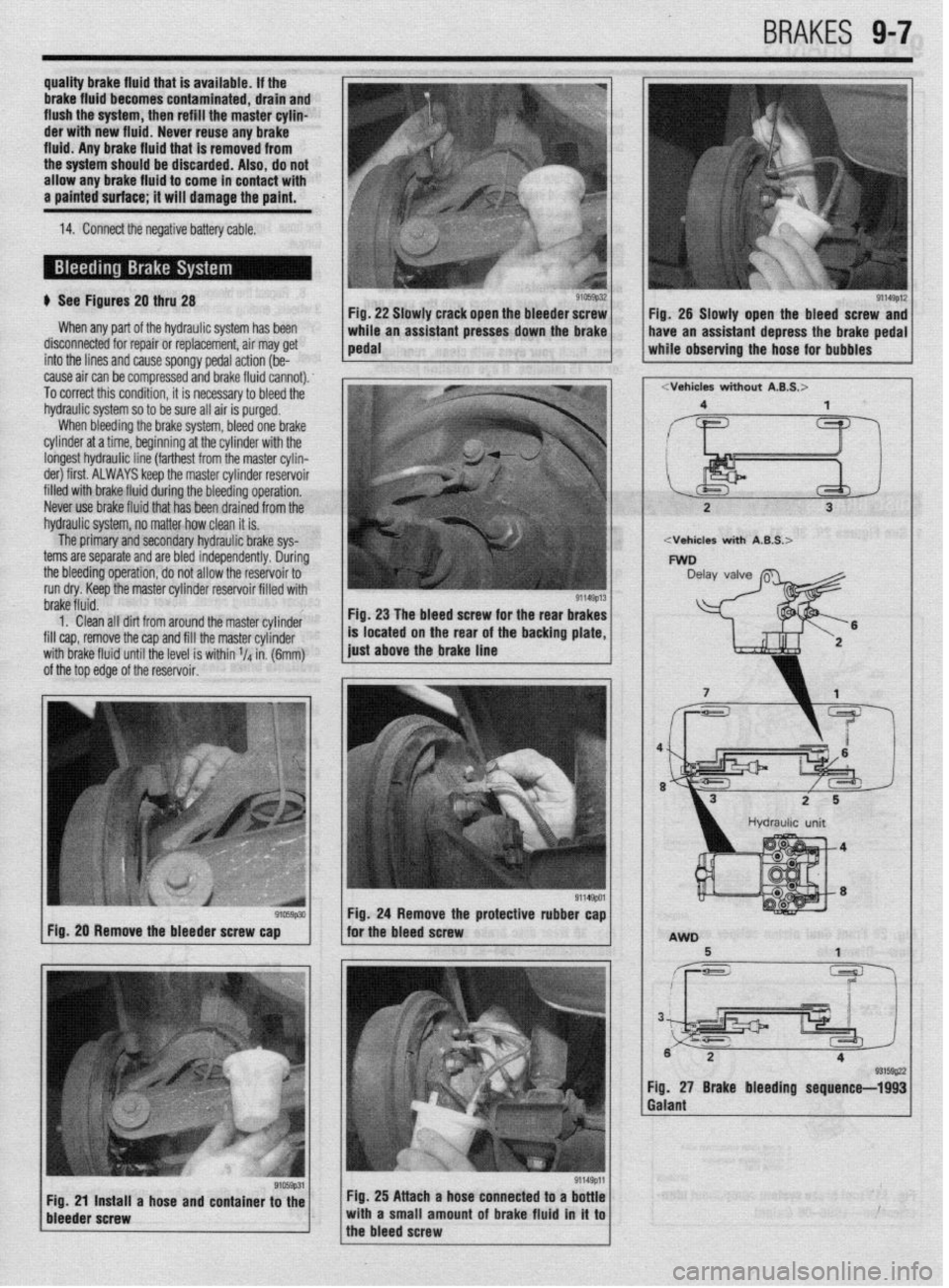
b See Figures 20 thru 28
When any part of the hydraulic system has been
disconnected for repair or replacement, air may get
into the lines and cause spongy pedal action (be-
cause air can be compressed and brake fluid cannot).
To correct this condition, it is necessary to bleed the
hydraulic system so to be sure all air is purged.
When bleeding the brake system, bleed one brake
cylinder at a time, beginning at the cylinder with the
longest hydraulic line (farthest from the master cylin-
der) first. ALWAYS keep the master cylinder reservoir
filled with brake fluid during the bleeding operation,
Never use brake fluid that has been drained from the
hydraulic system, no matter how clean it is.
The primary and secondary hydraulic brake sys-
terns are separate and are bled independently. During
the bleeding operation, do not allow the reservoir to
run dry. Keep the master cylinder reservoir filled with Fig. 22 Slawly crack open the bleeder screw
brake fluid.
1. Clean all dirt from around the master cylinder
fill cap, remove the cap and fill the master cylinder
with brake fluid until the level is within V4 in. (6mm)
of the top edge of the reservoir. Fig, 23 The bleed screw for the rear brakes
91059p30 Fig. 20 Remove the bleeder screw cap Fig. 28 Slowly open the bleed screw and
Fig, 27 Brake bleeding sequence-1993
Galant
Fig. 25 Attach a hose connected to a bottle
with a small amount of brake fluid in it to
the bleed screw
Page 344 of 408
9-8 BRAKES
2
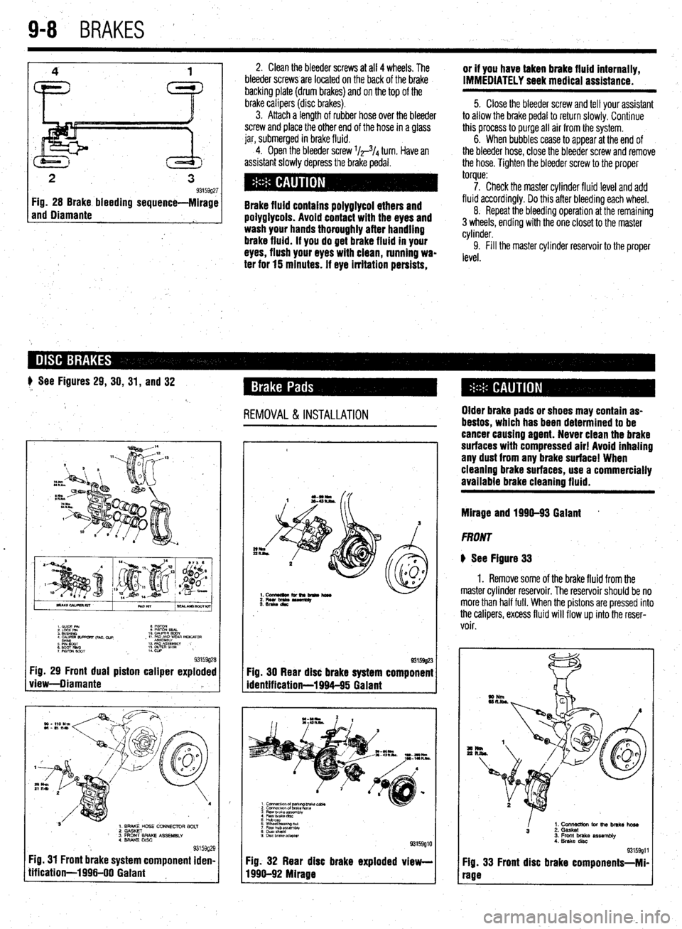
3 93159g27 Fig. 28 Brake bleeding sequence-Mirage
and Diamante
1
2, Clean the bleeder screws at all 4 wheels. The
bleeder screws are located on the back of the brake
backing plate (drum brakes) and on the top of the
brake calipers (disc
brakes). 3. Attach a length of rubber hose over the bleeder
screw and place the other end of the hose in a glass
jar, submerged in brake fluid.
4. Open the bleeder screw l/r3/4 turn. Have an
assistant slowly depress the brake pedal.
Brake fluid contains polyglycol ethers and
poiygiycois. Avoid contact with the eyes and
wash your hands thoroughly after handling
brake fluid. if you do get brake fluid in your
eyes, flush your eyes with clean, running wa-
ter for 15 minutes. if eye irritation persists, or if you have taken brake fluid internally,
IMMEDIATELY seek medical assistance.
5. Close the bleeder screw and tell your assistant
to allow the brake pedal to return slowly. Continue
this process to purge all air from the system.
6. When bubbles cease to appear at the end of
the bleeder hose, close the bleeder screw and remove
the hose. Tighten the bleeder screw to the proper
torque:
7. Check the master cylinder fluid level and add
fluid accordingly. Do this after bleeding each wheel,
8. Repeat the bleeding operation at the remaining
3 wheels, ending with the one closet to the master
cylinder.
9. Fill the master cylinder reservoir to the proper
level.
# See Figures 29, 30, 31, and 32
REMOVAL &INSTALLATION
.
I. C”lDE PIN 8 mm
2 LdcK Pm 9 PlSToN SEAL
3 WSHINO 10 WPER BODY
4 CALIPER 9lJPwRT ,pM. cue
sH’YlcYaT , 11 PmE~~yvEm INLKATclR
: EiT Rim 12 PAD As&&w
7 PWON mm ;: w&E” SHlM ,
93159g28 Fig. 29 Front dual piston caliper exploded
view-Diamante ‘a
L
1. BRAKE HOSE CONNECTOR BOLT
2. GASKET
’ 3. FRONT BRAKE ASSEMBLY
4. BRAKE DISC
93159g; Fig. 31 Front brake system component iden
tification-1996-00 Gaiant !9
I- 93159g23
Fig. 30 Rear disc brake system component
identification-1994-95 Galant
3 Rear brake ar?.embiy
4 Rear Drake dnc
5 Hubcap
6 Wheel baanng tit
7 Flew hub assemblv
8 chlstshteki
9 DISC brake adapter
93159glC
Fig. 32 Rear disc brake exploded view-
1996-92 Mirage Older brake pads or shoes may contain as-
bestos, which has been determined to be
cancer causing agent. Never clean the brake
surfaces with compressed air! Avoid inhaling
any dust from any brake surface! When
cieanlng brake surfaces, use a commercially
available brake cleaning fluid.
Mirage and 1990-93 Gaiant *
FRONT
@ See Figure 33
1. Remove some of the brake fluid from the
master cylinder reservoir. The reservoir should be no
more than half full. When the pistons are pressed into
the calipers, excess fluid will flow up into the reser-
voir.
I
1. Cons for the brake hose
3 2. Gasket
3. Front brake assembly
4. Brake disc
93159911
Fig. 33 Front disc brake components-Mi-
rage
Page 345 of 408
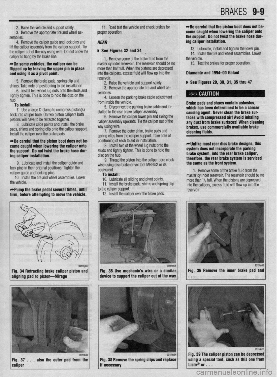
2. Raise the vehicle and support safely.
3. Remove the appropriate tire and wheel as-
semblies. 11. Road test the vehicle and check brakes for
proper operation. *Be careful that the piston boot does not be-
come caught when lowering the caliper onto
+ha n,.nnnr) lh nnt t&at thm hr&a hnra rlnr-
4. Remove the calmer auide and lock Dins and
REAR
lift the caliper assembly’from the caliper support. Tie
the caliper
out of the way using wire. 00 not allow the
caliper to hang by the brake line.
*On some vehicles, the caliper can be
flipped up by leaving the upper pin in place
and usinu it as a oivot ooint.
---- sa - . -.
5. Remove the brake pads, spring clip and
cl7knr T&n nn+n ,-A nrdtinninntn sir-4 inc+alhtinn
u See Figures 32 and 34 13. Lubricate, install and tighten the lower pin.
*
14. Install the tire and wheel assemblies. Lower
1, Remove some of the brake fluid from the the vehicle.
master cylinder reservoir. The reservoir should be no 15. Test the brakes for proper operation:
more than half full. When the p istons are depressed
into the calioers. excess fluid
3 111,113. ,(lhC ,,“LC “I p”3”‘““H’y I” a,u IIIaLcuIaLt”II. 6. Install two wheel lug nuts onto the studs and
:
lightly tighten. This is done to hold the disc on the
hub.
To install:
7. Use a large C-clamp to compress piston(s)
back into caliper bore. On two piston calipers both
pistons will have to be retracted together.
8. Lubricate slide points and install the brake
pads, shims and spring clip ont- +‘- --“n-* n**nnnA reservoir. /ill flow up into the
2. Raise the vehicle and support safely.
s tire and wheel as- 3. Remove the appropriate
semblies.
4. Loosen the parking bra
from inside the vehicle.
5. Disconnect the parking brake cable end in-
stalled to the rear brake caliper assembly.
6. Remove the caliper lower pin and swing the
caliper assembly upwards. Tie the caliper out of the
way using wire. Dlamante and 1994-00 Galant
k See Figures 29,30,31,35 thru 47
Brake pads and shoes contain asbestos,
which has been determined to be a cancer
causing agent. Never clean the brake sur-
faces with compressed air! Avoid inhaling
any dust from brake surfaces! When cleaning
brakes. use commerciallv avallable brake Ike cable adjustment
Install the caliper over the brake ,..uuG. 7. Remove the outer shim, brake pads and
.
ie caliper support. Take note of soring clips from tl
nositibning of eact
8
IndalI twn cleaning flutds. -
*Be careful that the piston boot does not be-
come caught when lowering the caliper onto
the support. Do not twist the brake hose dur-
ing caliper installation. I to aid in installation.
“. llluLull L..V of the wheel lug nuts onto the
studs and lightly tighten. This is done to hold the
disc on the hub.
Cl Thrm-l the nictnn into thP r!alinar hnre rlnrk-
*Unlike most rear disc brake designs, this
system does not incorporate the parking
brake system, into the rear brake caliper,
therefore, the rear brake system is serviced
9. Lubricate and install the caliper guide and
lock pins in their original positions. Tighten the
: caliper guide and locking pins.
10. Install the tire and wheel assemblies. Lower
the vehicle.
t *Pump the brake pedal several times, until
i
firm, before attempting to move the vehicle. V. ,,,lV”” ,,,V ~,“L”,’ III1” .IIV “..*.prv, ““I., “.“-a.
wise using disc brake driver tool MB9f52 or its
equivalent.
To install:
10. Lubricate all sliding and pivot points.
11. Install the brake pads, shims and spring clip
to the caliper support.
12. Install the caliper over ”
’ -’ ---I~ me oraxe paas. the same as the front system.
1. Remove some of the brake fluid from the
master cylinder reservoir. The reservoir should be no
more than r/a full. When the pistons are depressed
into the calipers, excess fluid will flow up into the
reservoir.
93159#2 Fig. 34 Retracting brake caliper piston and Fig. 35 Use mechanic’s wire or a similar
aligning pad to piston-hlirage device to support the caliper out of the way Fig. 36 Remove the inner brake pad and
. . .
93159p33 Fig, 37 . . . also the outer pad from the
caliper Fig. 39 The caliper piston can be depressed
Fig. 38 Remove the spring clips and replace
if necessary using a special tool, such as this one from
Lisle@ or . . .
Page 346 of 408
l
9-10 BRAKES
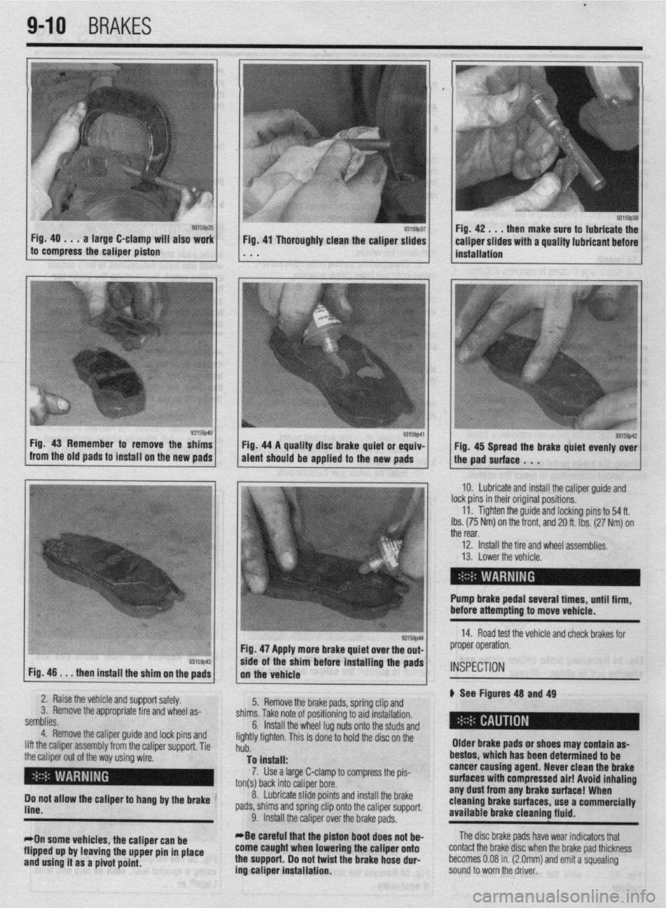
Fig. 40 . . . a large C-clamp will also work
to compress the caliper piston then make sure to lubricate the
Fig. 46
. . . then install the shim on the pads Fig. 47 Apply more brake quiet over the out-
/, the vehicle .Is/l*
wde of the sham before installing the pads
2. Raise the vehicle and support safely.
3. Remove the appropriate tire and wheel as-
semblies.
4. Remove the caliper guide and lock pins and
lift the caliper assembly from the caliper support. Tie
the caliper out of the way using wire.
( I ’ 5. Remove the brake pads, spring clip and
shims. Take note of positioning to aid installation.
6.
Do not allow the caliper to hang by the brake ’
line.
*On some vehicles, the caliper can be
flipped up by leaving the upper pin in place
and using it as a pivot point. Install the wheel lug nuts onto the studs and
lightly tighten. This is done to hold the disc on the
hub.
To install:
7. Use a large C-clamp to compress the pis-
ton(s) back into caliper bore.
_
8. Lubricate slide points and install the brake
pads, shims and spring clip onto the caliper support.
9. Install the caliper over the brake pads.
*Be careful that the piston boot
does not be- come caught when lowering the caliper onto
the support. Do not twist the brake hose dur-
ing caliper installation. Older brake pads or shoes may contain as-
bestos, which has been determined to be
cancer causing agent. Never clean the
brake
surfaces with compressed air! Avoid inhaling any dust from any brake surface! When
cleaning brake surfaces, use a commercially
available brake cleaning fluid. IO. Lubricate and install the caliper guide and
lock pins in their original positions.
11. Tighten the guide and locking pins to 54 ft.
Ibs. (75 Nm) on the front, and 20 ft. Ibs. (27 Nm) on
the rear,
12. install the tire and wheel assemblies.
13. Lower the vehicle.
Pump brake pedal several tlmes, until firm,
before attempting to move vehicle.
14. Road test the vehicle and check brakes for
proper operation.
INSPECTION
p See Figures 48 and 49
The disc brake pads have wear indicators that
contact the brake disc when the brake pad thickness
becomes 0.08 in. (2.0mm) and emit a squealing
sound to worn the driver.
Page 347 of 408
BRAK& 9-11
1, Disconnect the battery negative cable.
2. Raise the vehicle and support safely.
3. Remove the appropriate tire and wheel as-
---L,:--
SeIIIUIIM. 4. Loosen the parking brake cable adjustment
from inside the vehicle.
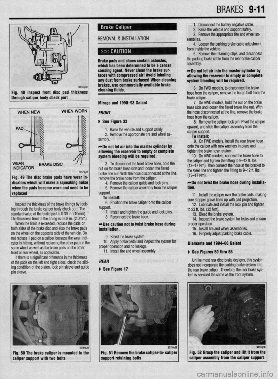
B957wJ FIQ. 48 Inspect front disc pad thickness Brake pads an
which has bee
causing agent
faces with con
any dust fmm
brakes, use cf Id shoes contaln
asbestos, !n determined to be a cancer
. Never clean the brake SUP
npressed air! Avoid inhaling
brake surfaces! When cleaning
lmmercially available brake
c
cleaning fluid 5. Remove the retaining clips, and disconnect
the parking brake cable from the rear brake caliper
assembly.
rflo not let ali into the master cylinder by
allowing the reservoir to empty or complete
system bleeding will be required.
6. On FWD models, to disconnect the brake
nose rrom me canoer. remove me
oamo
DOII nom me
through caliper body check port
Mirage and 199Q-93 Galant brake caliper. ’
7. On AWD models, hold the nut on the brake
hose side and loosen the flared brake line nut. With
the hose disconnected at the line, remove the brake
hose from the caliper.
8. Remove the caliper lock pin. Pivot the caliper
Inspect the thickness of the brake linings by look-
ing through the brake caliper body check port. The
standard value of the brake pad is 0.39 in. (1Omm).
The thickness limit of the lining is 0.08 in. (2.0mm).
When the limit is exceeded, replace the pads on
both sides of the brake disc and also the brake pads
on the wheel on the opposite side of the vehicle. Do
not replace 1 pad on a caliper because the wear indi-
cator is hitting, without replacing the other pad on the
same wheel as well as the brake pads on the other
front or rear wheel, as applicable.
If there is a significant difference in the thickness
of the pads on the left and right sides, check the slid-
ing condition of the piston,
IDCk pin sleeve and guide
pin sleeve. *Do not let air into the master cylinder by
allowing the reservoir to empty or complete
system bleeding will be required.
3. To disconnect the front brake hose, hold the
nut on the brake hose side and loosen the flared
brake line nut. With the hose disconnected at the line,
remove the brake hose from the caliper.
4.
RfXIIDVe the caliper guide and lock pins.
5. Remove the caliper assembly from the caliper
support.
To install:
6. Position the brake caliper onto the caliper
SUppOrt. 7. Install and tighten the guide and lock pins.
8. Reconnect the brake hose.
*Use caution not to twist brake hose during
installation.
9. Bleed the brake system.
10. Apply brake pedal and inspect the system for
proper operation and no leakage.
11. Install tire and wheel assembly.
REAR
Q See Figure 17 upward, and slide the caliper assembly from the
caliper support.
To install:
9. On FWD models, install the rear brake hose
onto the caliper with new washers in place and
tighten the brake hose retainer.
10. On AWD models, connect the brake hose to
the caliper and tighten the fitting to 9-12 ft. Ibs.
(13-17 Nm). Then connect the hose at the bracket to
the steel line and tighten the fitting to 9-12 ft. Ibs.
(13-17 Nm).
rDo not twist the brake hose during installa-
tlon.
11. Install the caliper over the brake pads, making
sure stopper grove lines up with pad projection.
12. Lubricate and install the lock pin and tighten
to 23 ft. tbs. (32 Nm).
13. Bleed the brake system.
14. Inspect the brake system for leaks and ensure
proper operation.
15. Install tire and wheel assemblies.
16. Properly adjust parking brake cable.
Diamante and 1994-08 Galant
8 See Ffgures 50
thN 55
Unlike most rear disc brake designs, this system
does not incorporate the parking brake system into
the rear brake caliper. Therefore, the rear brake sys-
tem is serviced the same as the front system.
FiQ. 50 The brake caliper is mounted to the Fig. 52 Grasp the caliper and Ilft it from the
eaiiper support with two bolts support retaining bolts caliper assembly from the caliper support
Page 348 of 408
l
942 BRAKES
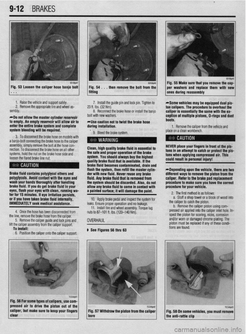
I 93155~46 Fig, 53 Loosen the caliper hose banjo bolt
1 Fig. 54 . . , then remove the bolt from the . * . fitting
1 I Raise the vehicle and support safely.
2. Remove the appropriate tire and wheel as-
sembly.
*Do not allow the master cylinder reservoir
to empty. An empty reservoir will allow air to
enter the entire brake system and complete 7. Install the guide pin and lock pin. Tighten to
23 ft. Ibs. (32 Nm).
8. Reconnect the brake hose of install the banjo
bolt with new washers.
*Use caution not to twist the brake hose
during installation.
system bleeding will be required.
9. Bleed the brake system.
3. To disconnect the brake hose on models with
a banjo-bolt connecting the brake hose to the caliper
assembly, simply remove the bolt at the hose con-
nection. To disconnect the brake hose on all other
systems, hold the nut on the brake hose side and
loosen the flared brake line nut. Clean, high quality brake fluid is essential to
the safe and proper operation of the brake
system. You should always buy the highest
quality brake fluid that is available. If the
brake fluid becomes contaminated, drain and
flush the system, then refill the master cylin-
Brake fluid contains polyglycol ethers and
poly~lycols. Avoid contact with the eves and
wash your hands thoroughly after handling
brake fluid. if you do get brake fluid In your
eyes, flush your eyes with clean, running wa-
ter for 15 minutes. If eye irritation persists,
or if you have taken brake fluid internally,
IMMEDIATELY seek medical assistance.
4. Once the hose has been disconnected from der with new fluid. Never reuse any brake
fluid. Anv brake fluid that is removed from
the systum should be discarded. Also, do not
allow any brake fluid to come in contact with
a painted surface; it will damage the paint.
10. Apply brake pedal and inspect the system for
leaks. Ensure proper operation and no leakage.
11. Install tire and wheel assembly. Torque lug
nuts to 87-101 ft. Ibs. (120-140 Nm).
the line, remove the brake hose from the caliper,
5. Remove the caliper guide and lock pins and
lift the caliper assembly from the caliper support,
To install:
6. Position the caliper onto the caliper support.
OVERHAUL
b See Figures 56 thru 63 1 Fig. 55 Make sure that you remove the cop-
per washers and replace them with new
ones during reassembly
*Some vehicles may be equipped dual pis-
ton calipers. The procedure to overhaul the
caliper is essentially the same with the ex-
ception of multiple pistons, D-rings and dust
boots.
1. Remove the caliper from the vehicle and
place on a clean workbench.
NEVER place your fingers in front of the pis-
tons in an attempt to catch or protect the pis-
tons when applying compressed air. This
could result in personal injury!
*Depending upon the vehicle, there are two
different ways to remove the piston from the
caliper. Refer to the brake pad replacement
procedure to make sure you have the correct
procedure for your vehicle.
2. The first method is as follows:
a. Stuff a shop towel or a block of wood into
the caliper to catch the piston.
b. Remove the caliper piston using com-
pressed air applied into the caliper inlet hole. In-
spect the piston for scoring, nicks, corrosion
and/or worn or damaged chrome plating. The
piston must be replaced if any of these condi-
tions are found.
Page 349 of 408
BRAKiS 9-13
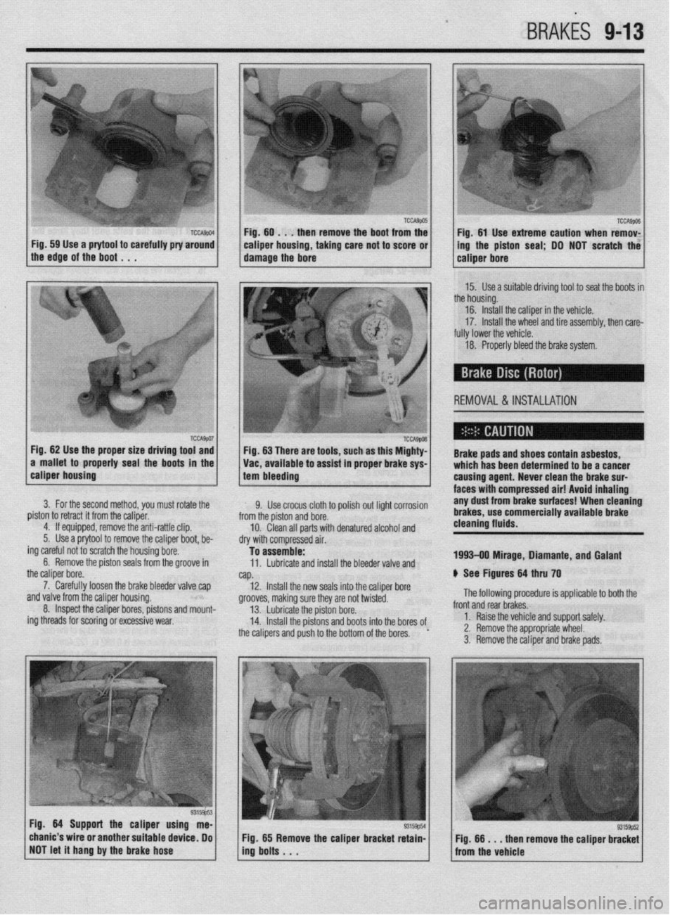
Fig. 59 Use a prytool to carefully pry around 1
the edge of the boot , , . caiper housing, taking care not to score or 1
damage the bore ing the piston seal; DO NOT scratch the
15. Use a suitable driving tool to seat the boots in
the housing.
16. Install the caliper in the vehicle.
17. Install the wheel and tire assembly, then care-
fully lower the vehicle.
18. Properly bleed the brake system.
REMOVAL &INSTALLATION
Fig. 62 Use the proper size driving tool and
a mallet to properly seal the boots in the Fig. 63 There are tools, such as this Mighty-
Vat, available to assist in proper brake sys- Brake pads and shoes contain asbestos,
which has been determined to be a cancer
calmer housino
1 tam hlasrlinn . --~-~~~v
3. For the second method, you must rotate the
piston to retract it from the caliper.
4. If equipped, remove the anti-rattle clip.
5. Use a prytool to remove the caliper boot, be-
ing careful not to scratch the housing bore.
6. Remove the piston seals from the groove in
the caliper bore.
7. Carefully loosen the brake bleeder valve cap
~nrl \I~IWJ frnm the r~linor hnlwinn
I causina aaent. LL.....” rlrr.. .I.,. l.uLr I..”
Yll” .UI”Y ll”lll LIIb rro,spl tI”“Jlly. 8. Inspect the caliper bores, pistons and mount-
ing threads for scoring or excessive wear,
--... -.---...= ’ I.twla lilci(lll Lllli uranl$ au,- faces with-compressed air! Avoid Inhaling
9. Use crocus cloth to polish out light corrosion any dust from brake surfaces! When cleaning
from the piston and bore. brakes, use commercially available brake
10. Clean all parts with denatured alcohol and cleaning fluids.
dry with compressed air.
To assemble:
11. Lubricate and install the bleeder valve and 1993-09 Mirage, Diamante, and Galant
NP. 6 See Figures 64 thru 70
12. Install the new seals into the caliper bore
nrnnlrhr m”lr;nn Clln-. M..-.., nrn n.4 h..‘“‘“~ The following procedure is applicable to both the ytvvvca, lllanllly 3”IC o,ey ale II”, IWI~LCL. 13. Lubricate the piston bore.
14. Install the pistons and boots into the bores of
the calipers and push to the bottom of the bores. ’ front and rear brakes.
1. Raise the vehicle and support safely.
2. Remove the appropriate wheel.
3. Remove the caliper and brake pads.
Fia. 64 Suoaarl the calmer usina me-
., -----= -..- chanic’s wire or another suitable device, Do
NOT let it hang by the brake hose Fig. 65 Remove the caliper bracket retain-
ing bolts . . . Fig. 66 m . . then remove the caliper bracket
from the vehicle
Page 350 of 408
l
9-14 BRAKES
-
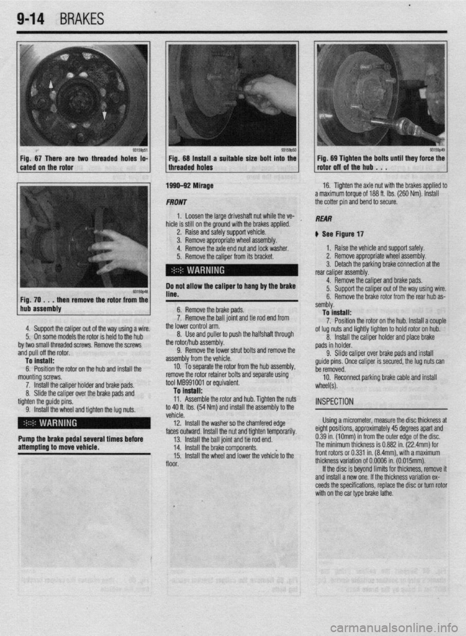
two threaded hoks to- Fig. 68 tnstatt a suitable size bolt into the Fig. 69 Tighten the bolts until they force the
threaded holes rotor off of the hub . . .
1 hub assembly
4. Support the caliper out o
5. On some models the rote
by two small threaded screws. Remove the screws
.mrl n,,ll nff thn rntnr
6. Remove the brake pads.
7. Remove the ball joint and tie rod end from
., 3
me lower control arm.
8. Use and puller to push the halfshaft through f the way using a wire.
)r is held to the hub
ml” p”” “II crw l”L”l. To install:
6. Position the rotor on the hub and install the
mounting screws.
7. Install the caliper holder and brake pads.
8. Slide the caliper over the brake pads and
tighten the guide pins.
9. Install the wheel and tighten the lug nuts. the rotor/hub assembly.
9. Remove the lower strut bolts and remove the
bly from the vehicle.
To separate the rotor from the hub assembly,
sallluly. To install:
7. Position the rotor on the hub. Install a couple
of lug nuts and lightly tighten to hold rotor on hub.
asseml
10.
remove the rotor retainer bolts and separate using
tool MB991001 or equivalent.
To Install:
11. Assemble the rotor and hub. Tighten the nuts
to 40 ft. Ibs. (54 Nm) and install the assembly to the 8. Install the caliper holder and place brake
pads in holder.
9. Slide caliper over brake paAl- --,I inr+*.rli
guide pins. Once caliper is secure1
ho
mmnmrl
I”> a, I” II 13m11
YI, the lug nuts can
U” IUIII”“““.
10. Reconnect parking brake cable and install
wheel(s).
INSPECTION
venae.
12. Install the washer so the chamfered edge Using a micrometer, measure the disc thickness at
.I LL- *.* 1 I
faces outward. Install the nut and tighten temporarily. eignr posmons, approxlmarely
43 aegrees apan ana
Pump the brake pedal several times before
13. Install the ball joint and tie rod end. 0.39 in. (10mm) in from the outer edge of the disc.
attempting to move vehicle.
14. Install the brake components. The minimum thickness is 0.882 in. (22.4mm) for
15. Install the wheel and lower the vehiclk to the front rotors or 0.331 in. (8.4mm), with a maximum
floor. thickness variation of 0.0006 in. (0.015mm).
If the disc is beyond limits for thickness, remove it
and install a new one. If the thickness variation ex-
ceeds the specifications, replace the disc or turn rotor
with on the car type brake lathe.
I
_,