MITSUBISHI DIAMANTE 1900 Repair Manual
Manufacturer: MITSUBISHI, Model Year: 1900, Model line: DIAMANTE, Model: MITSUBISHI DIAMANTE 1900Pages: 408, PDF Size: 71.03 MB
Page 321 of 408
SUSPENSION AND STEERING 8-25
1994-00 Galant and 1997-00 Diamante
1, Raise and safely support the vehicle securely
on jackstands.
2. Remove the wheel and tire assembly.
3. Support the rear axle using a jack or other
suitable device.
4. Remove the trailing arm-to-knuckle connec-
tion.
5. Remove the trailing arm-to-body mounting
through-bolt and remove the trailing arm.
To install: 6. Install the trailing arm and install the trailing
arm-to-body mounting through-bolt. Tighten the bolt
to 99-114 ft. lbs. (137-157 Nm).
7. Install the trailing arm-to-knuckle connection.
Tighten the bolt to 85-99 ft. Ibs. (118-137 Nm).
8. Remove the axle support device.
9. install the wheel and tire assembly.
10. Lower the vehicle.
1992-96 Diamante
1. Raise and safely support the vehicle securely
on jackstands.
2. Remove the wheel and tire assembly.
3. Remove the brake rotor.
4. Remove the hub and bearing assembly.
5. Support the rear axle using a jack or other
suitable device.
6. Remove the lower shock absorber-to-trailing
arm connection.
7. Remove the stabilizer bar link-to-trailing arm
connection.
8. Remove the tie rod end-to-trailing arm con-
nection.
9. Remove the lower control arm-to-trailing arm
connection.
10. Remove the trailing arm-to-body mounting
through-bolt and remove the trailing arm.
To install: 11, Install the trailing arm and install the trailing
arm-to-body mounting through-bolt. Tighten the bolt
to lOl-116ft. Ibs. (14C-160 Nm).
12. Install the trailing arm-to-lower control arm
connection. Tighten the bolt to 101-116 ft. Ibs.
(140-l 60 Nm).
13. Install the tie rod end-to-trailing arm connec-
tion. Tighten the nut to 21 ft. Ibs. (29 Nm).
14. Install the stabilizer bar link-to-trailina arm
connection. Tighten the nut to 29 ft. Ibs. (40 im).
15. Install the lower shock absorber-to-trailing
arm connection. Tighten the bolt to 65 ft. Ibs. (90
Nm).
16. Remove the axle support device.
17. Install the hub and bearing assembly.
18. Install the brake rotor.
19. Install the wheel and tire assembly.
20. Lower the vehicle.
REMOVALANDINSTALLATION '
1990-93 Galant
1. Raise and support the vehicle safely.
2. Place a jack under the rear axle and suspen-
sion assembly.
3. Remove the self-locking nuts and crossmem-
her bracket.
d.--- -.
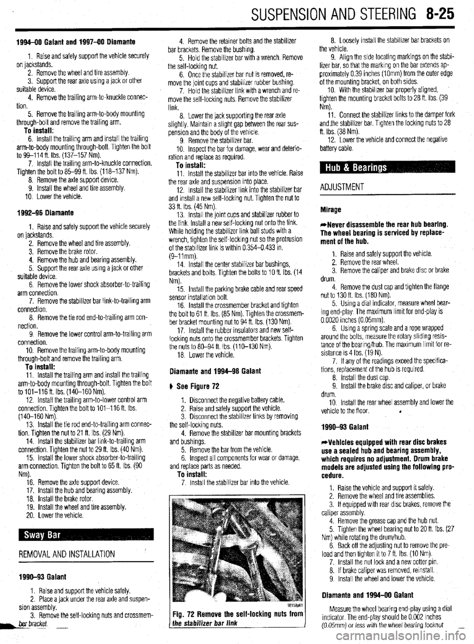
Fig. 72 Remove the self-locking nuts from
the stabilizer bar link 8. Loosely install the stabilizer bar brackets on
the vehicle.
9. Align the side locating markings on the stabi-
lizer bar, so that the marking on the bar extends ap-
proximately 0.39 inches (1Omm) from the outer edge
of the mounting bracket, on both sides.
10. With the stabilizer bar properly aligned,
tighten the mounting bracket bolts to 28 ft. Ibs. (39
Nm).
11. Connect the stabilizer links to the damper fork
andjhe stabilizer bar. Tighten the locking nuts to 28
ft. Ibs. (38 Nm).
12. Lower the vehicle and connect the negative
battery cable.
ADJUSTMENT
1990-93 Galant
*Vehicles equipped with rear disc brakes
use a sealed hub and bearing assembly,
which requires no adjustment. Drum brake
models are adjusted using the following pro-
cedure.
1. Raise the vehicle and support it safely.
2. Remove the wheel and tire assemblies.
3. If equipped with rear disc brakes, remove the
caliper assembly.
4. Remove the grease cap and the hub nut.
5. Tighten the wheel bearing nut to 20 ft. Ibs. (27
Nm) while rotating the drum/hub.
6. Back off the adjusting nut to remove the pre-
load and then tighten it to 7 ft. Ibs. (10 Nm).
7. Install the nut lock and a new cotter pin.
8. If brake caliper was removed, reinstall.
9. Install the wheel and lower the vehicle.
Diamante and 1994-00 Galant
Measure the wheel bearing end-play using a dial
indicator. The end-play should be 0.002 inches
(0.05mm) or less with the wheel bearing locknut _
Page 322 of 408
8-26 SUSPENSION AND STEERING
torqued to specifications. The wheel bearings are
sealed units and are not adjustable. If defective, re-
placement is the only option.
REMOVAL &INSTALLATION
Mirage
7996-92 MODELS
1. Raise the vehicle and support safely.
2. Remove the tire and wheel assembly.
3. If equipped with rear disc brakes, remove the
caliper from the disc and remove the brake disc.
4. Remove the dust cap and bearing nut. Do not
use an air gun to remove the nut.
5. Remove the outer wheel bearing.
6. Remove the drum and/or axle hub with the
inner wheel bearing and the grease seal.
7. Remove the grease seal and remove the inner
bearing.
To install: 8. Lubricate the inner bearing and install to the
drum or hub.
9. Install a new grease seal.
10. To determine if the self-locking nut is
reusable:
a. Screw in the self-locking nut until about
0.07-0.11 in. (2-3mm) of thread is visible under
the nut.
b. Measure the torque required to turn the
self-locking nut counterclockwise.
c. The lowest allowable torque is 48 inch Ibs.
(6 Nm). If the measured torque is less than the
specification, replace the nut.
11. Install the drum and/or hub to the vehicle.
12. Lubricate and install the outer wheel bearing
to the spindle.
13. Tighten the self-locking nut to 108-145 ft.
Ibs. (150-200 Nm).
14. Set up a dial indicator and measure the end-
play while moving the hub or drum in and out. If the
endplay exceeds 0.008 in. (0.002mm) retorque the
nut. If still beyond the limit, replace the bearings.
15. Install the grease cap and wheel assembly.
7993-60 MODELS
*Never disassemble the rear hub bearing.
The wheel bearing is serviced by replace-
ment of the hub.
1. If equipped with ABS, remove the wheel
speed sensor.
2. Raise and safely support the vehicle.
3. Remove the rear wheel.
4. Remove the caliper and brake disc or brake
drum.
5. Remove the dust cap and flange nut.
6. Remove the rear hub assembly.
To install: 7. Install the rear hub assembly using a new
flange nut. Tighten the flange nut to 130 ft. Ibs. (180
Nm).
8. install the dust cap.
9. Install the wheel speed sensor if removed.
The air gap should be 0.012-0.035 in. (0.3-0.9mm).
10. Install the brake disc and caliper, or brake
drum.
11. Install the rear wheel assembly and lower the
vehicle to the floor.
1990-93 Galant
DRUM BRAKE VEHICLES
1. Raise the vehicle and support it safely.
2. Remove the wheel and tire assemblies.
3. Remove the grease cap and the hub nut.
4. Remove the brake drum. The outer bearing
will fall out while the drum is coming off. Do not drop
it. Remove the hub and rotor assembly.
5. Pry out and discard the oil seal.
6. Remove the inner bearing.
*Check the bearing races. If any scoring,
heat checking or damage is noted, they
should be replaced. When bearing or races
need replacement, replace them as a set.
7. If the bearings and races are to be replaced,
drive out the race with a brass drift.
To install: 8. Before installing new races, coat them with
wheel bearing grease. Drive into place with proper
size driver. Make sure they are fully seated.
9. Thoroughly pack the bearings and lubricate
the hubs with wheel bearing grease. Install the inner
bearing and coat the lip and rim of the grease seal
with grease. Drive the seal into place with a seal dri-
ver.
10. Install the drum assembly on the axle.
11, Lubricate and install the outer wheel bearing,
washer and nut. To properly adjust the wheel bearing
preload:
a. Tighten the wheel bearing nut to 20 ft. Ibs.
(27 Nm) while rotating the drum.
b. Back off the adjusting nut to remove the
preload, then tighten it to 7 ft. Ibs. (10 Nm).
c. Install the nut lock and a new cotter pin.
12. Install the wheel and lower the vehicle.
O/SC BRAKE VEHICLES
1. Raise the vehicle and support safely.
2. Remove the tire and wheel assembly.
3. Remove the bolt(s) holding the speed sensor
bracket to the knuckle and remove the assembly from
the vehicle.
The speed sensor has a pole piece projecting
from it. This exposed tip must be protected
from impact or scratches. Do not allow the
oole oiece to contact the toothed wheel dur-
in0 removal or installation.
4. Remove the caliper from the brake disc and
suspend with a wire.
5. Remove the brake rotor.
6. Remove the grease cap, locking nut and
tongued washer.
7. Remove the rear hub and bearing assembly.
*The rear hub assembly can not be disas-
sembled. If bearing replacement is required,
replace the assembly as a unit.
8. If replacing the hub assembly, remove the
two bolts securing the speed sensor ring to the hub.
To install: 9. Install the speed sensor to the hub and bear-
ing assembly. Tighten the mounting bolts to 8 ft. Ibs.
(11 Nm). 10. Install the hub and bearing assembly to the
axle shaft.
11, Install the tongued washer and a new locking
nut. Tighten the locknut to 144-188 ft. Ibs. (200-260
Nm). Once the locknut has been properly torqued,
crimp the nut flange over the slot in the spindle, and
install the grease cap.
12. Install the brake caliper and rotor.
13. Install the speed sensor and tighten the
mounting bolt to 8 ft. Ibs. (11 Nm).
14. Install the tire and wheel assembly.
Be sure to pump the brake pedal until it’s
firm, before moving vehicle.
1994-00 Galant
DRUM BRAKE VEHICLES
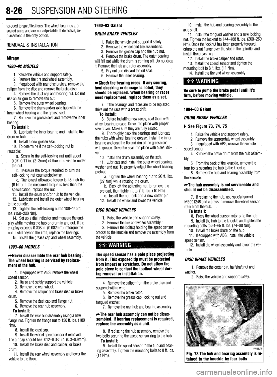
) See Figure 73, 74, 75
1. Raise the vehicle and support safely.
2. Remove the appropriate wheel assembly.
3. If equipped with ABS, remove the vehicle
speed sensor.
4. Remove the brake drum from the hub assem-
bly.
5. From the back of the knuckle, remove the
four bolts securing the hub to the knuckle.
6. Remove the hub and bearing assembly from
the knuckle.
*The hub assembly is not serviceable and
should not be disassembled.
7. If replacing the hub, use special socket
MB991248 and a press to remove the wheel sensor
rotor from the hub.
To install: 8. Press the wheel sensor rotor onto the hub.
9. Install the hub to the knuckle and tighten the
mounting bolts to 54-65 ft. Ibs. (74-88 Nm).
10. Install the brake drum on the hub.
11. If equipped with ABS, install the vehicle
speed sensor.
12. Install the wheel assembly and lower the ve-
hicle.
O/SC BRAKE VEHICLES
1. Remove the cotter pin, halfshaft nut and
washer.
2. Raise the vehicle and support safely.
Fig. 73 The hub and bearing assembly is re-
tained to the knuckle by four bolts
Page 323 of 408
SUSPENSION AND STEERING 8-27
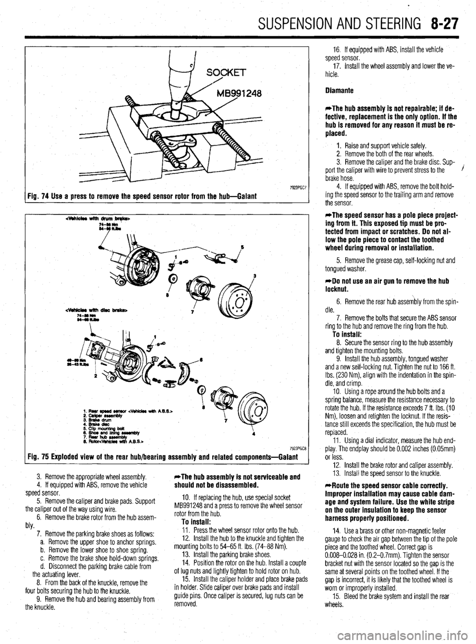
7923PGC7 Fig. 74 Use a press to remove the speed sensor rotor from the hub-Galant
dhk4w with drum,brqb
7923PGCE Fig. 75 Exploded view of the rear hub/bearing assembly and related components=Galant
3. Remove the appropriate wheel assembly. *The hub assembly is not serviceable and 4. If equipped with ABS, remove the vehicle should not be disassembled. speed sensor.
5. Remove the caliper and brake pads, Support
the caliper out of the way using wire.
6. Remove the brake rotor from the hub assem-
hl
10. If replacing the hub, use special socket
MB991248 and a press to remove the wheel sensor
rotor from the hub.
To install: WY. 7. Remove the parking brake shoes as follows:
a. Remove the upper shoe to anchor springs.
b. Remove the lower shoe to shoe spring.
c. Remove the brake shoe hold-down springs.
d. Disconnect the parking brake cable from
the actuating lever.
8. From the back of the knuckle, remove the
four bolts securing the hub to the knuckle.
9. Remove the hub and bearing assembly from
the knuckle. Il. Press the wheel sensor rotor onto the hub.
12. Install the hub to the knuckle and tighten the
mounting bolts to 54-65 ft. tbs. (74-88 Nm).
13. Install the parking brake shoes,
14. Position the rotor on the hub. Install a couple
of lug nuts and lightly tighten to hold rotor on hub.
15. Install the caliper holder and place brake pads
in holder. Slide caliper over brake pads and install
guide pins. Once caliper is secured, lug nuts can be
removed. 16. If equipped with ABS, install the vehicle
speed sensor.
17. Install the wheel assembly and lower the ve-
hicle.
Diamante
*The hub assembly is not repairable; if de-
fective, replacement is the only option. If the
hub is removed for any reason it must be re-
placed.
1. Raise and support vehicle safely.
2. Remove the both of the rear wheels.
3. Remove the caliper and the brake disc. Sup-
port the caliper with wire to prevent stress to the /
brake hose.
4. If equipped with ABS, remove the bolt hold-
ing the speed sensor to the trailing arm and remove
the sensor.
*The speed sensor has a pole piece project-
ing from it. This exposed tip must be pro-
tected from impact or scratches. Do not al-
low the pole piece to contact the toothed
wheel during removal or installation.
5. Remove the grease cap, self-locking nut and
tongued washer.
*Do not use an air gun to remove the hub
locknut.
6. Remove the rear hub assembly from the spin-
dle.
7. Remove the bolts that secure the ABS sensor
ring to the hub and remove the ring from the hub.
To install: 8. Secure the sensor ring to the hub assembly
and tighten the mounting bolts.
9. Install the hub assembly, tongued washer
and a new self-locking nut. Tighten the nut to 166 ft.
Ibs. (230 Nm), align with the indentation in the spin-
dle, and crimp.
IO. Using a rope around the hub bolts and a
spring balance, measure the resistance necessary to
rotate the hub. If the resistance exceeds 7 ft. Ibs. (IO
Nm), loosen and retighten the locknut. If the resis-
tance still exceeds the specification, the hub must be
replaced.
11. Using a dial indicator, measure the hub end-
play. The endplay should be 0.002 inches (0.05mm)
or less.
12. Install the brake rotor and caliper assembly.
13. Install the speed sensor to the knuckle.
*Route the speed sensor cable correctly.
Improper installation may cause cable dam-
age and system failure. Use the white stripe
on the outer insulation to keep the sensor
harness properly positioned.
14. Use a brass or other non-magnetic feeler
gauge to check the air gap between the tip of the pole
piece and the toothed wheel. Correct gap is
0.008-0.028 in (0.2-0.7mm). Tighten the sensor
bracket nut with the sensor located so the gap is the
same at several points on the toothed wheel. If the
gap is incorrect, it is likely that the toothed wheel is
worn or improperly installed.
15. Bleed the brake system and install the rear
wheels.
Page 324 of 408
. . . ,.x ..-~ .-....,, _s_s”., .._ ” *
8-28 SUSPENSION AND STEERING
REMOVAL&INSTALLATION
199%93 Mirage 1994-00 Mirage and Galant
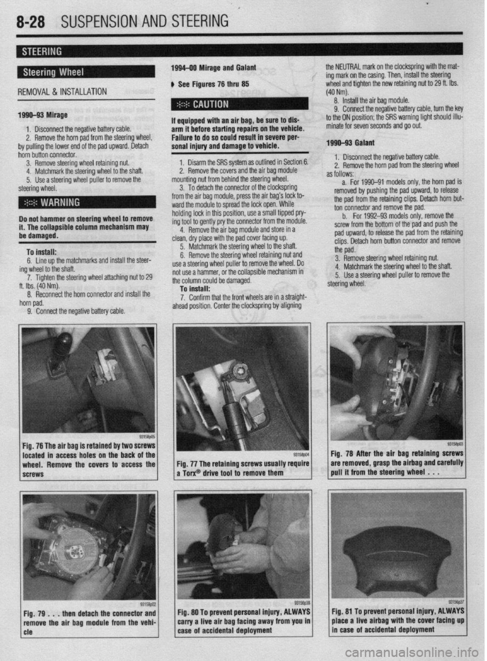
b See Figures 76 thru 85 the NEUTRAL mark on the clockspring with the mat-
f ing mark on the casing. Then, install the steering
wheel and tighten the new retaining nut to 29 ft. Ibs.
(40 Nm).
8. Install the air bag module.
1. Disconnect the negative battery cable.
2. Remove the horn pad from the steering wheel,
by pulling the lower end of the pad upward. Detach I
If aqui
arm it --.-.- ---.-...= .-r-.‘- -.. _..- ._.. - -
Failure to do so could result in severe per-
sonal injury and damage to vehicle. pped with an air bag, be sure to dls- hnfnra sfarfinn rmairs on the vehicle.
9. Connect the negative battery cable, turn the key
to the ON position; the SRS warning light should illu-
minate for seven seconds and go out.
1990-93 Galant
hbin butin connector.
3. Remove steering wheel retaining nut:
. . . .‘ .
a. .a I <.
4. Matcnmarlc me steering wneel to me snan.
5. Use a steering wheel puller to remove the
steering wheel.
Do not hammer on steering wheel to remove
it. The collapsible column mechanism may
ha rlsmwmd.
To install:
6. Line up the matchmarks and install the steer-
ing wheel to the shaft.
7. Ti flhten the steering wheel attaching nut to 29
ft. Ibs. (40 Nm).
8. Reconnect the horn connector and install the
horn pad.
9. Connect the neaative battetv cable. 1. Disarm the SRS system as outlined in Section 6.
^ m *I
sand the air bag module
.,A +L. m++-,g w,,eel,
*. I z. Remove me cover
mounting nut from behill” ~IK ~(G~G!I
3. To detach the connector of the clocKsprmfl
from the air bag module, press the air bag’s lock to-
ward the module to spread the lock open. While
holding lock in this position, use a small tipped pry-
ing tool to gently pry the connector from the module.
4. Remove the air bag module and store in a
clean, dry place with the pad cover facing up.
5. Matchmark the steering wheel to the shaft.
6. Remove the steering wheel retaining nut and
use a steering wheel puller to remove the wheel. Do
not use a hammer, or the collapsible mechanism in
the column could be damaged.
To install:
7. Confirm that the front wheels are in a straight-
ahead position. Center the clocksprinfl by aligning 1. Disconnect the negative battery cable.
2. Remove the horn oad from the steerino wheel
as follows:- - - - r d
a. For 1990-91 models only, the horn pad is
removed by pushing the pad upward, to release
the pad from the retaining clips. Detach horn but-
ton connector and remove the pad.
b.
For 1992-93 models only, remove the
screw from the bottom of the pad and push the
pad upward, to release the pad from the retaining
clips. Detach horn button connector and remove
the pad.
3. Remove steering wheel retaining nut.
4. Matchmark the steering wheel to the shaft.
5. Use a steering wheel puller to remove the
steering wheel.
Fig. 76 The air bag is retained by two 8
located in access holes on the back
wheel. Remove the covers to access the
screws Fig. 78 After the air baa
retainino screws
Fig. 77 The retaining screws usually require are removed, grasp the airbag andiarefully
a Torx@ drive tool to remove them pull it from the steering wheel . . .
then detach the connector and Fig. 80 To prevent personal injury, ALWAYS fig. 81 To prevent personal Injury, ALWAYS
ove the air bag module from the vehi- carry a live air bag facing away from you in place a live airbag with the cover facing up
Page 325 of 408
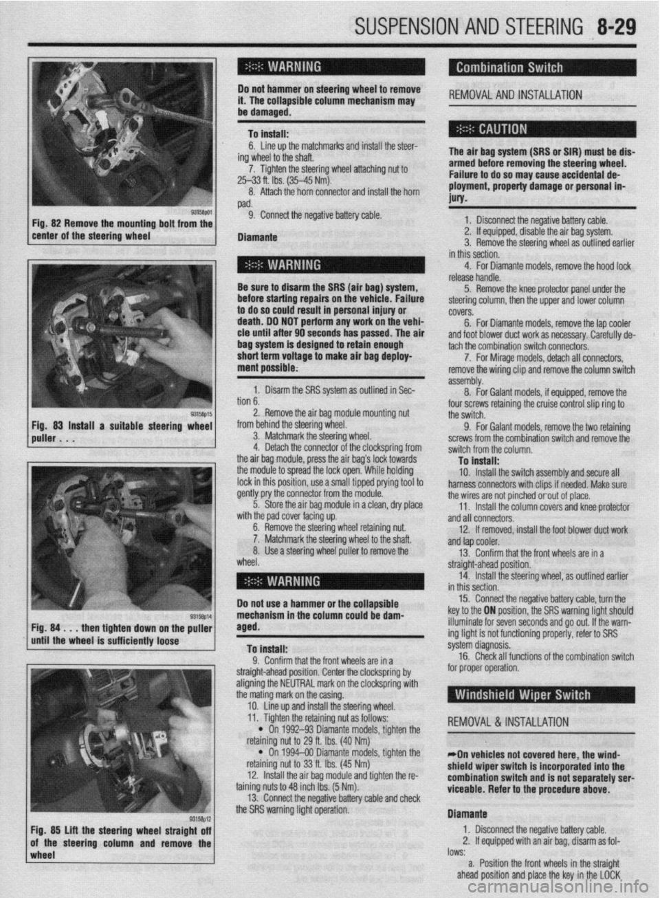
SUSPENSION AND STEERING 8-29
i ’
Do not hamme i4 l-ha nnlhnr !r on steering wheel to remove
,,. , II= ,,,,,,Jfble column mechanism may REMOVALANDINSTALLATION
I
be damaged.
To install:
ing
7.
6. Line up the matchmarks and install the steer-
/heel to the shaft.
Tighten the steering wheel attaching nut to
25-33 ft. Ibs. (35-45 Mm).
8. Attach the horn connector and install the horn
pad.
9. Connect the negative battery cable.
Diamante The air bag system (SRS or SIR) must be dis-
armed before removing the steering wheel.
Failure to do so may cause accidental de-
ployment, property damage or personal in-
MY.
1 Rscnnnnd the nnmtivn hattm rJhle . I._“” . ..I_. . ..I *.-~ _...” ““.‘“‘, _““._. 2. If equipped, disable the air bag system.
3. Remove the steering wheel as outlined earlier
in this section.
Be sure to disarm the SRS (air bag
before starting repairs OI
to do so could result in p
death. DO NOT perform ;
cle until after 90 seconds has passed. The ai
bag system is designed to retain enough
short term voltage to make air bag deploy-
ment possible; I) system,
n the vehicle. Failure
lersonal injury or
any work on the vehi-
ir 4. For Diamante models, remove the hood lock
release handle.
5. Remove the knee protector panel under the
steering column, then the upper and lower column
covers.
6. For Diamante models, remove the lap cooler
and foot blower duct work as necessary. Carefully de-
non
b. 1. Disarm the SRS system as outlined in Sec-
. . ^ I assembly. tach the combination switch connecto&.
8. -
7. For Mirage models, detach all connectors,
For Galant models, if equipped, remove the remove the wiring clip and remove the column switch
2. Remove the air bag module mounting nut
from behind the steering wheel.
3. Matchmark the steering wheel.
4. Detach the connector of the clockspring from
the air baq module, press the air baa’s lock towards four screws retaining the cruise control slip ring to
the switch.
9. For Galant models, remove the two retaining
screws from the combination switch and remove the
switch from the column.
Tn install: the modub to spread the lock open:While holding
lock in this position, use a small tipped prying tool to
gently pry the connector from the module.
5. Store the air bag module in a clean, dry place
..# ,I I I .
ut.
Iaft. wlrn me paa cover racmg up.
6. Remove the steering wheel retaining nl
7. Matchmark the steering wheel to the sl
8. Use a steering wheel puller to remove the
wheel. - . . - _-. . _
10. Install the switch assembly and secure all
harness connectors with clips if needed. Make sure
the wires are not pinched orout of place.
11. Install the column covers and knee protector
and all connectors.
12. If removed, install the foot blower duct work
anfl tan cnnler -..- .-
r --- ”
13. Confirm that the front wheels are in a
straight-ahead position.
14. Install the steering wheel, as outlined earlier
in thir
Do not use a hammer or the ~r”---‘~‘- 15. Connect the negative battery cable, turn the
key to the ON position, the SRS warning light should
NW down
rinntlv
wImpl* the puller
iem Fig. 84 . . . then tighte
until the wheel is suffL,,,,, lVvoV
To install:
0 Pnnfirm that thn frnnt whnalc ,?A in , .I. ““llllllll u,a, ,110 ll”lll I.ll~rJlJ CnIj 111 a
straight-ahead position. Center the clockspring by
aligning the NEUTRAL mark on the clockspring with
the mating mark on the casing.
10. Line up and install the steering wheel. illuminate for seven seconds and go out. If the warn-
ing light is not functioning properly, refer to SRS
s’ .’ ystem cllagnosls.
16. Check all functions of the combination switch
for proper operation.
wheel lows:
a. Position the front wheels in the straight
ahead position and place the key in the LOCK
93158p12 Fig. 85 Lift the steering wheel straight off
of the steering column and remove the 11. Tighten the retaining nut as follows:
REMOVAL &INSTALLATION
l On 1992-93 Diamante models, tighten the
nut to 29 ft. Ibs. (40 Nm) retammg I
l On
retaining I
12. lnstal
taining nuts 1
13. Conn
“... . ..” .‘“J...*.” ‘&.“WSJ Y..“.” . ..rn” VII”“..
the SRS warning light operation. 1994-00 Diamante models, tighten the
iut to 33 ft. Ibs. (45 Nm)
II the air bag module and tighten the r&
:o 48 inch Ibs. (5 Nm).
wt the rwnative hatim rahle ami rhwk
*On vehicles not covered here, the wind-
shield wiper switch is incorporated into the
combination switch and is not separately serl
viceable. Refer to the procedure
above.
Diamante
1. Disconnect the negative battery cable.
2. If equipped with an air bag, disarm as fol-
I” .L
Page 326 of 408
8-30 SUSPENSION AND STEERING
position. Remove the key from the ignition lock
cylinder.
b. Disconnect the negative battery cable and
insulate the cable end with high-quality electrical
tape or similar non-conductive wrapping.
c. Wait at least 1 minute before working on
the vehicle. The air bag system is designed to re-
tain enough voltage to deploy the air bag for a
short period of time even after the battery has
been disconnected.
3. Remove the steering wheel. as outlined ear-
lier in this section.
4. Remove the hood lock release handle.
5. Remove the switches from the knee protector
below the steering column, and remove the exposed
retaining screws. Then remove the knee protector.
6. Remove the column covers.
7. Remove necessary duct work and detach the
windshield wiper switch connectors. +
8. Remove the retaining screws and remove the
windshield wiper switch assembly from the steering
column.
To install: 9. Install the wiper switch to the steering col-
umn and connect the connectors.
IO. Install any removed duct work.
11. Install the column covers.
12. Install the knee protector and switches.
13. Install the hood release handle.
14. Confirm that the front wheels are in a straight
ahead position. Install the steering wheel, as outlined
earlier in this section.
15. Connect the negative battery cable and check
the windshield wiper and washer for proper opera-
tion
REMOVAL &INSTALLATION
The air bag system (SRS or SIR) must be dis-
armed before removing the steering wheel.
Failure to do so may cause accidental de-
ployment, property damage or personal in-
jury.
1. If equipped, properly disarm the air bag sys-
tern:
2. Disconnect the negative battery cable.
3. Remove the hood lock release lever from the
lower panel.
4. Remove the lower instrument panel knee pro-
tector.
5. Remove the ductwork with the lower knee
panel and remove the steering wheel assembly.
Use proper steering wheel puller equipment
when removing the steering wheel. The use
of a hammer for removal could damage the
collapsible mechanism within the column.
6. Remove the lower and upper steering column
covers.
7. For Diamante models, remove the lap cooler
and foot shower duct work.
8. If necessary, remove the clip that holds the
wiring harness against the steering column. 9. Detach all necessary connectors.
10. For Galant and Diamante models, remove the
retaining screws, then remove the entire column
switch/clockspring assembly from the left side of the
steering column.
11. For Diarnante models, remove the mounting
screws from the ignition switch and pull the switch
from the interlock cylinder.
12. Insert the key into the steering lock cylinder
and turn to the
ACC position.
13. With a small, pointed tool, push the lock pin
of the steering lock cylinder inward and pull the lock
cylinder out.
14. Remove the key reminder switch, if equipped.
To install: 15. For Mirage, install the lock cylinder in the
lock cylinder bracket. Make sure the cylinder oper-
ates properly before breaking off the heads of the
special bolts, if the bracket was replaced.
16. For Galant and Diarnante models, install the
lock cylinder into the interlock housing. Be sure the
lock pin snaps into place. Install the ignition switch
into the interlock housing. Align the keyway of the ig-
nition switch with the lock cylinder and secure with
the mounting screws.
17. For Galant and Diamante models, install the
column switch/clockspring assembly to the and con-
nect the harness.
18. install the key reminder switch, if equipped.
19. Attach the harness connections and install
the wiring clip.
20. If removed, install the lap cooler and foot
shower duct work.
21. Install the steering column upper and lower
covers.
22. If necessary, install the knee protector and the
steering wheel.
23. Install the hood lock release lever.
24. Connect the negative battery cable, enable the
air bag system, and check the ignition switch and
lock for proper operation.
REMOVALANDINSTALLATION
Mirage and Galant
I. Disconnect the negative battery cable. If
equipped, disarm the air bag system.
2. Remove the hood lock release lever from the
lower panel.
3. Remove the lower instrument panel knee pro-
tector.
4. Remove the ductwork with the lower knee
panel and remove the steering wheel assembly.
*Use proper steering wheel puller equip-
ment when removing the steering wheel. The
use of a hammer for removal could damage
the collapsible mechanism within the col-
umn.
5. Remove the lower steering column cover.
6. Remove the upper steering column cover.
7. Remove the clip that holds the wiring harness
against the steering column.
8. For Galant models, insert the key into the
steering lock cylinder and turn to the ACC position.
9. For Galant models, using a small pointed
tool, push the lock pin of the steering lock cylinder
inward and pull the lock cylinder out. IO. For Galant models, remove the key reminder
switch, if equipped.
11. Unplug the ignition switch harness connec-
tor. Remove the ignition switch mounting screws and
pull the switch from the steering lock cylinder.
*Vehicles equipped with automatic
transaxle have safety-lock systems and will
have a key interlock cable installed in a slide
lever on the side of the key cyfinder. Care-
fully unhook the interlock cable from the lock
cylinder while withdrawing the cylinder from
the lock housing.
To install:
*To remove the steerlng lock, use a hack-
saw or equivalent to cut the special bolts
through the bracket. The bracket and bolts
must be replaced with new ones.
12. With the ignition key removed, install the
slide lever and the interlock cable to the steering lock
cylinder. Apply grease to the interlock cable and in-
stall the cylinder into the lock housing. Check for
normal operation of the interlock system.
13. Install the ignition switch into the rear of the
lock cylinder housing. Be sure to align the keyway of
the ignition switch with interlock cylinder.
14. Attach the harness connections and install
the wiring clip.
15. Install the steering column upper and lower
covers.
16. Install the knee protector.
17. Connect the negative battery cable, enable the
air
bag system (if equipped) and check the ignition
switch and lock for proper operation.
Diamante
Work MUST NOT be started until at least 90
seconds after the ignition switch is turned to
the LOCK position and the negative battery
cable is disconnected from the battery. This
will allow time for the air bag system backup
power supply to deplete its stored energy
preventing accidental air bag deployment
which could result in unnecessary air bag
system repairs and/or personal injury.
I. Disconnect the negative battery cable.
2. Disarm the air bag system, as outlined in
Section 6.
3. Remove the steering wheel, as outlined ear-
lier in this section.
4. Remove the hood lock release handle.
5. Remove the switches from the knee protector
below the steering column and remove the exposed
retaining screws. Then remove the knee protector.
6. Remove the steering column upper and lower
covers. Use care removing the covers to prevent
breakage of alignment tabs.
7. Remove lap cooler and foot shower
duct work. Detach the ignition switch harness connectors.
8. Remove mounting screws from the ignition
switch and pull switch from interlock cylinder.
To install: 9. Install ignition switch into interlock housing.
Align keyway of ignition switch with lock cylinder and
secure with mounting screws.
IO. Connect the ignition switch electrical harness
Plug.
Page 327 of 408
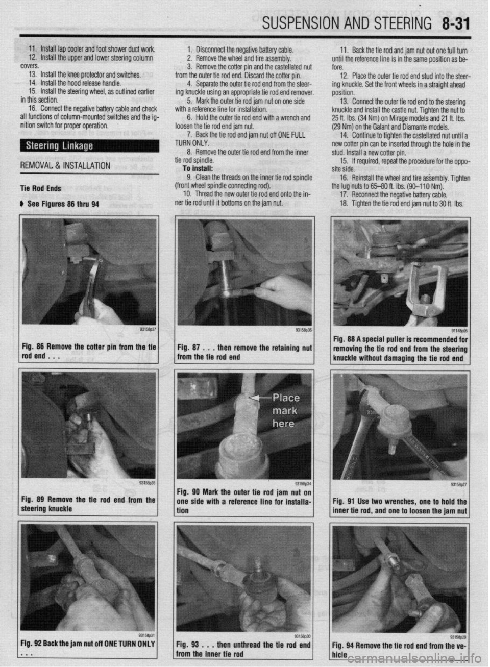
I
SUSPENSION AND STEERING 8-31
11. Install lap cooler and foot shower duct work.
1.’ Disconnect the negative battery cable. 11.
12. Install the upper and lower steering column Back the tie rod and jam nut out one full turn
2. Remove the wheel and tire assembly. until the reference line is in the same position as be-
covers.
3. Remove the cotter pin and the castellated nut
fore.
13. Install the knee protector and switches.
12. Place the outer tie rod end stud into the steer-
14. Install the hood release handle. from the outer tie rod end. Discard the cotter pin.
4. Separate the outer tie rod end from the steer-
15. Install the steering wheel, as outlined earlier
ing knuckle using an appropriate tie rod end remover. ing knuckle. Set the front wheels in a straight ahead
in this section. position.
16. Connect the negative battery cable and check 5. Mark the outer tie rod jam nut on one side 13. Connect the outer tie rod end to the steering
with a reference line for installation.
all functions of column-mounted switches and the ig-
Hold the outer tie rod end with a wrench and knuckle and install the castle nut. Tighten the nut to
6.
nition switch for proper operation,
loosen the tie rod end jam nut. 25 ft. Ibs. (34 Nm) on Mirage models and 21 ft. Ibs.
(29 Nm) on the Galant and Diamante models.
7. Back the tie rod end jam nut off ONE FULL
TURN ONLY. 14. Continue to tighten the castellated nut until a
new cotter pin can be inserted through the hole in the
8. Remove the outer tie rod end from the inner
REMOVAL&INSTALLATION
Tie Rod Ends tie rod spindle.
To install:
9. Clean the threads on the inner tie rod spindle
(front wheel spindle connecting rod).
10. Thread the new outer tie rod end onto the in- stud. Install a new cotter pin.
15. If required, repeat the procedure for the oppo-
site side,
16. Reinstall the wheel and tire a&embly. Tighten
the lug nuts to 65-80 ft. Ibs. (90-l 10 Nm).
u See Figures 86 thru 94 ner tie rod until it bottoms on the jam nut. 17. Reconnect the negative battery cable.
18. Tighten the tie rod end jam nut to 30 ft. Ibs.
g3’5a~51 Fig. 89 Remove the Be rod end from the
steering knuckle *
Fig. 92 Back the jam nut off ONE TURN OMLY
. * m Fig. 98 . . .
then unthread the tie rod end
Fig. 94 Remove the tie rod end from the ve-
from the inner tie rod
hicle Fig. 88 A special puller is recommended for
removing the tie rod end from the steering
knuckle without damaging the tie rod end
Fig. 91 Use two wrenches, one to hold the
inner tie rod, and one to loosen the jam nut
93158p29
Page 328 of 408
.
8132 SUSPENSION AND STEERING
(42 Nm) on Mirage and 36-39 ft. tbs. (49-53 Nm)
on Galant and Diamante models.
19. Have the front end alignment checked, and
adjusted if necessary.
Inner Tie Rods
11. Loosen the inner tie rod end nut from the
steering gear and remove the inner tie rod end.
To install: 12. Using a new lock plate, install the tie rod end
and tighten the tie rod to 65 ft. Ibs. (90 Nm). REMOVAL &INSTALLATION 13. Bend the tabs of the new lock plate to secure
1. Raise the front of the vehicle and support it
on jackstands.
2. Remove the wheel.
3. Remove the cotter pin and the outer tie rod
ball joint stud nut. Note the position of the steering
linkage.
4. Wire brush the threads on the tie rod shaft
and lubricate with penetrating oil.
5. Using a suitable ball joint separator tool, re-
move the tie rod ball joint from the steering knuckle.
6. Loosen the locknut and remove the tie rod
end from the tie rod. Count the number of complete
turns it takes to completely remove it.
7. Remove the tie rod-to-steering gear locknut.
8. Remove the clamps that secure the flexible
boot to the steering gear.
9. Slide the boot from the inner tie rod and re-
move the boot.
IO. Bend the lock plate tabs from the inner tie rod
end nut. the inner tie rod end.
14. Slide the boot onto the steering gear and se-
cure it with new clamps.
15. Install the outer tie rod end to the steering
gear locknut.
16. Install the outer tie rod end, turning it in ex-
actly as many turns as it was to remove the old one.
Make sure it is correctly positioned in relationship to
the steering linkage.
22. Have a front end alignment performed. 17. Connect the outer tie rod end to the steering
knuckle and install the castle nut. Tighten the nut to
25 ft. Ibs. (34 Nm,) on the Mirage and 21 ft. Ibs. (29
Nm) on the Galant and Diamante models.
18. Install a new cotter pin to the castle nut.
19. Tighten the tie rod end locking nut to 30 ft.
Ibs. (42 Nm) on the Mirage and 36-39 ft. Ibs. (49-53
Nm) on the Galant and Diamante models.
20. Install the wheel and tire assembly.
21. Lower the vehicle.
Mirage
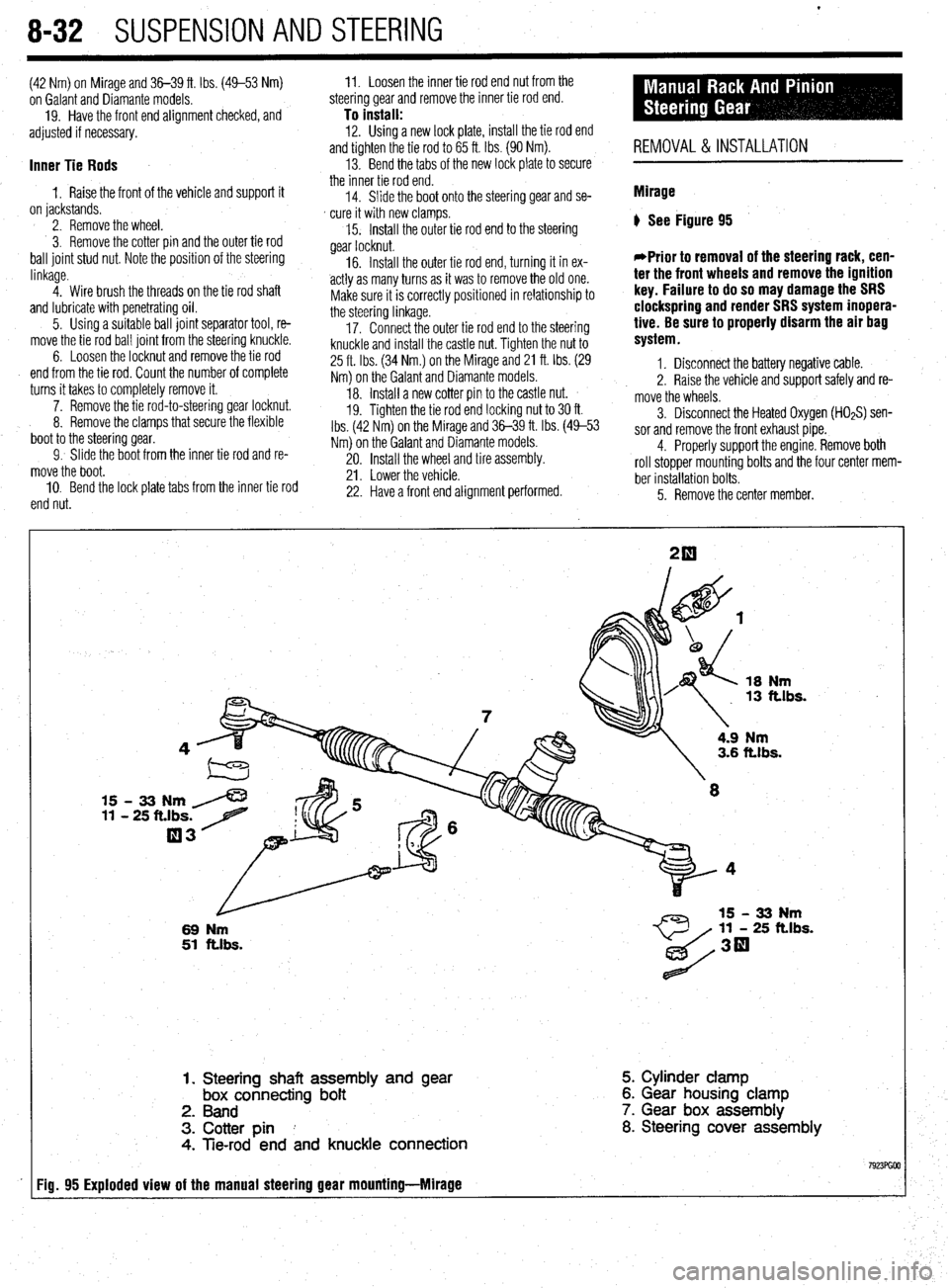
) See Figure 95
*Prior to removal of the steering rack, cen-
ter the front wheels and remove the ignition
key. Failure to do so may damage the SRS
clockspring and render SRS system inopera-
tive. Be sure to properly disarm the air bag
system.
1. Disconnect the battery negative cable.
2. Raise the vehicle and support safely and re-
move the wheels.
5. Remove the center member. 3. Disconnect the Heated Oxygen (HOzS) sen-
sor and remove the front exhaust pipe.
4. Properly support the engine. Remove both
roll stopper mounting bolts and the four center mem-
ber installation bolts.
18
Nm 13 ft.lbs.
15 - 33 Nm /
11 - 25 ft.lbs. 7
03
L
69 Nm
51 ftlbs.
4.9 Nm 3.6 ft.lbs.
11 - 25 ft.lbs.
1. Steering shaft assembly and
gear box connecting bolt
2. Band
3. Cotter pin I
4. Tie-rod end and knuckle connection 5. Cylinder clamp
6. Gear housing clamp
7. Gear box assembly
8. Steering cover assembly
Fig. 95 Exploded view of the manual steering gear mounting-Mlrage
Page 329 of 408
SUSPENSION AND STEERING 8-33
*Matchmark the pinion input shaft of the
rack to the lower steering column joint for in-
stallation purposes.
6. Remove the pinch bolt holding the lower
steering column joint to the rack and pinion input
shaft.
7. Remove the cotter pins and disconnect the tie
rod ends from the steering knuckle.
8. Remove the rack and pinion steering assem-
bly and its rubber mounts from the right side of the
vehicle.
To install: 9. Align the matchmarks of the input shaft and
install the rack to the vehicle.
10. Secure the rack using the retainer clamps and
bolts. Tighten the bolts to 51 ft. Ibs. (70 Nm).
11. Tighten the steering column pinch bolt to 13
ft. Ibs. (18 Nm).
12. Install the center member.
13. Install the front exhaust pipe.
14. Connect the HO$ sensor.
15. Connect the tie rod ends to the steering
knuckles and tighten the castle nuts to 25 ft. Ibs. (34
Nm). Install new cotter pins.
16. Install the wheels and connect the negative
battery cable.
17. Have a front end alignment performed.
REMOVAL &INSTALLATION
Diamante
FRONT
*Prior to removal of the steering gear box,
center the front wheels and remove the igni-
tion key. Failure to do so may damage the
SRS clock spring and render SRS system in-
operative.
1. Disconnect the negative battery cable.
2. Disconnect the front exhaust pipe.
3. If equipped with AWD, remove the transfer
case assembly.
4. Remove the bolt holding the lower steering
column joint to the rack and pinion input shaft.
5. Remove the cotter pins and disconnect the tie
rod ends.
6. Remove the left and right frame members.
7. Remove the stabilizer bar bracket.
8. If equipped with four-wheel steering, discon-
nect the lines going to the rear pump.
9. Remove the rack and pinion steering assem-
bly and its rubber mounts. Move the rack to the right
to remove it from the crossmember.
To install: IO. Install the rack and mounting bolts. Tighten
the bolts to 51 ft. Ibs. (70 Nm). When installing the
rubber rack mounts, align the projection of the
mounting rubber with the indentation in the cross:
member. Install the pinch bolt.
11. Connect the pressure and return lines to the
rack and to the rear pump, if equipped.
12. Install the frame members and tighten the
bolts to 43-51 ft. Ibs. (60-70 Nm).
13. Connect the tie rods and install new cotter
pins. 14. Install the transfer case and front exhaust
pipe.
15. Refill the reservoir and bleed the system.
16. Have a front end alignment performed.
REAR
1. Disconnect the negative battery cable.
2. Raise the vehicle and support safely.
3. Drain the power steering fluid.
4. Remove the main muffler assembly.
5. Remove the rear shock absorber lower
mounting bolts.
6. Using the proper equipment, support the
weight of the rear differential. Remove the 2 small
crossmember brackets.
7. Remove the large self-locking crossmember
mounting nuts on the differential side.
8. Remove the oil line clamp bolts.
9. Remove the pressure tubes.
IO. Hold the tie rod ends stationary and remove
the tie rod end nuts. Remove the tie rod ends from
the trailing arms.
11. Remove the mounting bolts and remove the
rear steering gear.
To install: 12. Secure the unit to the crossmember. Move
the power cylinder piston rod over its full stroke to
determine its neutral position.
13. Align the tie rod ends with the holes in the
trailing arms and install the nuts. Adjust the length of
the tie rods with the nuts if necessary. The difference
in length between the 2 tie rod ends should not ex-
ceed 0.04 in. (1 mm). The nuts’ torque specification is
42 ft. Ibs. (58 Nm).
14. Replace the O-rings and install the pressure
tubes. Clamp in place.
15. Install the large self-locking crossmember
mounting nuts on the differential side. Tighten to
80-94 ft. Ibs. (110-130 Nm).
16. Remove the support equipment.
17. Install the 2 small crossmember brackets.
18. Install the shock mounting bolts.
19. Install the muffler assembly.
20. Refill the reservoir and bleed the system.
21. Have a front end alignment performed. _
Galant
1990-93 MODELS
1. Disconnect the negative battery cable.
2. Drain the power steering fluid.
3. Raise the vehicle and support safely.
4. Remove the bolt holding lower steering col-
umn joint to the rack and pinion input shaft.
5. Remove the transfer case, if equipped.
6. Remove the cotter pins and using the proper
tools, separate the tie rod ends from the steering
knuckle.
7. Locate the triangular brace near the stabilizer
bar brackets on the crossmember and remove both
the brace and the stabilizer bar bracket.
8. Support the center crossmember.
9. Remove the through-bolt from the round roll
stopper and remove the rear bolts from the center
crossmember.
10. Disconnect the front exhaust pipe, if
equipped with FWD.
11. Disconnect the power steering fluid pressure
pipe and return hose from the rack fittings. Plug the
fittings to prevent excess fluid leakage. 12. Lower the crossmember slightly.
13. Remove the rack and pinion steering assem-
bly and its rubber mounts. Move the rack to the right
to remove from the crossmember. Tilt the assembly
downward and remove from the left side of the vehi-
cle. Use caution to avoid damaging the boots.
To install: 14. Install the rack and install the mounting bolts. Tighten the mounting bolts to 43-58 ft. Ibs. (60-80
Nm). When installing the rubber rack mounts, align
the projection of the mounting rubber with the inden-
tation in the crossmember.
15. Connect the power steering fluid lines to the
rack.
16. Connect the exhaust pipe, if removed.
17. Raise the crossmember into position. Install
the center member mounting bolts and tighten to 72
ft. Ibs. (100 Nm). Install the roll stopper bolt and new
nut. Tighten nut to 47 ft. Ibs. (65 Nm).
18. Install the stabilizer bar brackets and brace.
19. Connect the tie rod ends and tighten nuts to
25 ft. Ibs. (34 Nm).
20. Install the transfer case, if removed. Check
and fill fluid.
21. Refill the reservoir with power steering fluid
and bleed the system.
22. Have a front end alignment performed.
1994-M MODELS
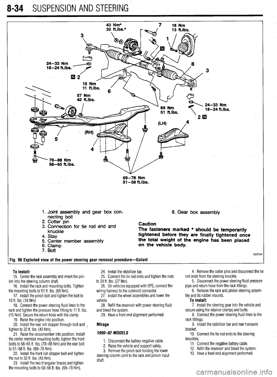
+ See Figure 96
Prior to removal of the steering gear box,
center the front wheels and remove the igni-
tion key. Failure to do so may damage the
SRS clock spring and render SRS system in-
operative.
1. Disconnect the negative battery cable.
2. Raise and properly support the vehicle.
3. Remove both front wheel assemblies.
4. Remove the bolt holding lower steering col-
umn joint to the rack and pinion input shaft.
5. Remove the stabilizer bar.
6. Remove the cotter pins, and using joint sepa-
rator MB991 113 or equivalent, disconnect the tie rod
ends from the steering knuckle.
7. On vehicles equipped with Electronic Control
Power steering (EPS), detach the wiring harness from
the solenoid connector.
8. Locate the two triangular braces near the
crossmember and remove both.
9. Support the center crossmember. Remove the
through-bolt from the front round roll stopper and re-
move the bolts securing the center crossmember.
10. Remove the center crossmember. ,
Il. Properly support the engine and remove the
rear roll stopper through-bolt.
12. Disconnect the power steering fluid pressure
pipe and return hose from the rack fittings. Plug the
fittings to prevent excessive fluid leakage.
13. Remove the clamp bolts and the two bolts se-
curing the rack assembly to the chassis.
14. Remove the rack and pinion steering assem-
bly and its rubber mounts.
*When removing the rack and pinion as-
sembly, tilt the assembly to the vehicle side
of the compression lower arm and remove
from the left side of the vehicle.
Page 330 of 408
8-34 SUSPENSION AND STEERING'
Fig. 96 Exploded view of the power steering gear removal procedure- -Galant 43 Nm*
7 18 Nm
24-33 Nm
18-24 ttlbs.
15 Nm . 11 ftlbs. 6
57 Nm
42 ft.lbs.
\1- 69 Nm
51 ft.lbs. 24-33 Nm
18-24
ft.1 bs.
’ 78-86 Nm
58-65 ft.lbs.
69-78
Nm 51-58 ftlbs.
1. Joint assembly and gear box con-
necting bolt
2. Cotter pin
3. Connection for tie rod end and
knuckle
4. Stay
5. Center member assembly
6. Clamp
7. Bott
I 8. Gear box assembly
Caution
The fasteners marked * should be temporarily
tightened before they are finally tightened once
the total weight of the engine has been placed
on the vehicle
body.
7923PGAl
To install:
15. Center the rack assembly and insert the pin-
ion into the steering column shaft.
16. Install the rack and mounting bolts. Tighten
the mounting bolts to 51 ft. Ibs. (69 Nm).
17. Install the pinch bolt and tighten the bolt to
13 ft. Ibs. (18 Nm).
18. Connect the power steering fluid lines to the
rack and tighten the pressure hose fitting to 11 ft. Ibs.
(15 Nm). Secure the return hose with the clamp.
19. Raise the engine into position.
20. Install the rear roll stopper through-bolt and I
tighten to 32 ft. Ibs. (43 Nm).
21. Raise the crossmember into position. Install
_ the center member mounting bolts; tighten the front
bolts to 58-65 ft. Ibs. (78-88 Nm) and the rear bolt
to 51-58 ft. Ibs. (69-78 Nm).
22. Install the front roll stopper bolt and tighten
the nut to 32 ft. Ibs. (43 Nm).
23. Install the two triangular braces and tighten
the mounting bolts to 50-56 ft. Ibs. (69-78 Nm). 24. Install the stabilizer bar.
25. Connect the tie rod ends and tighten the nuts
to 20 ft. Ibs. (27 Nm).
26. On vehicles equipped with EPS, connect the
wiring harness to the solenoid connector.
27. Install the wheel assemblies and lower the
vehicle.
28. Refill the reservoir with power steering fluid
and bleed the system.
29. Have a front end alignment performed.
Mirage
1990-92 MODELS
I. Disconnect the battery negative cable.
2. Raise the vehicle and support safely.
3. Remove the pinch bolt holding the lower
steering column joint to the rack and pinion input
shaft. 4. Remove the cotter pins and disconnect the tie
rod ends from the steering’knuckle.
5. Disconnect the power steering fluid pressure
pipe and return hose from the rack fittings.
6. Remove the rack and pinion steering assem-
bly and its rubber mounts.
To install:
7. Install the steering gear into the vehicle and
secure using the retainer clamps and bolts.
8. Connect the power steering fluid lines to the
rack fittings.
9. Install the stabilizer bar and rear transaxle
bracket.
10. Connect the tie rod ends to the steering
knuckles.
ll= Connect the negative battery cable.
12. Refill the reservoir and bleed the system.
13. Have a front end alignment performed.