MITSUBISHI DIAMANTE 1900 Repair Manual
Manufacturer: MITSUBISHI, Model Year: 1900, Model line: DIAMANTE, Model: MITSUBISHI DIAMANTE 1900Pages: 408, PDF Size: 71.03 MB
Page 331 of 408
SUSPENSION AND STEERING 8-35
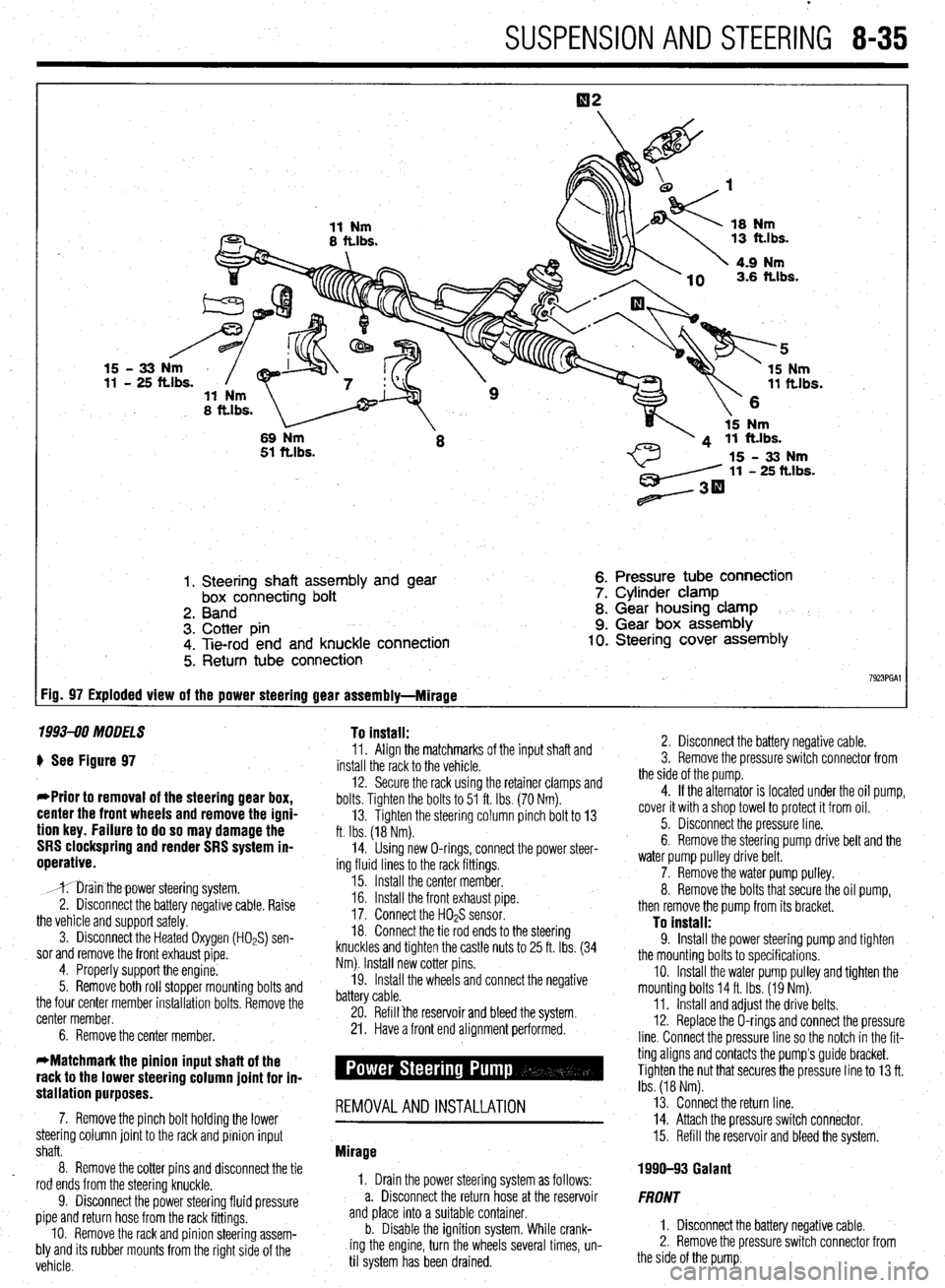
1. Steering shaft assembly and gear
box connecting bolt
2. Band
3. Cotter pin
4. Tie-rod end and knuckle connection
5. Return tube connection 6. Pressure tube connection
7. Cylinder clamp
8. Gear housing clamp
9. Gear box assembly 10. Steering cover assembly
7923PGAl FiD= 97 Exploded view of the power steering gear assembly-Mirage
1993-90 MODELS To install:
) See Figure 97
*Prior to removal of the steering gear box,
center the front wheels and remove the igni-
tion key. Failure to do so may damage the
SRS clockspring and render SRS system in-
operative.
,mr;iin thepower steering system.
2. Disconnect the battery negative cable. Raise
the vehicle and support safely.
3. Disconnect the Heated Oxygen (HOPS) sen-
sor and remove the front exhaust pipe.
4. Properly support the engine.
5. Remove both roll stopper mounting bolts and
the four center member installation bolts. Remove the
center member.
6. Remove the center member. 11. Align the matchmarks of the input shaft and
install the rack to the vehicle.
12. Secure the rack using the retainer clamps and
bolts. Tighten the bolts to 51 ft. Ibs. (70 Nm).
13. Tighten the steering column pinch bolt to 13
ft. Ibs. (18 Nm).
14. Using new O-rings, connect the power steer-
ing fluid lines to the rack fittings.
15. Install the center member.
16. Install the front exhaust pipe.
17. Connect the H02S sensor.
18. Connect the tie rod ends to the steering
knuckles and tighten the castle nuts to 25 ft. Ibs. (34
Nm). Install new cotter pins.
19. Install the wheels and connect the negative
battery cable.
20. Refill ‘the reservoir and bleed the system.
21. Have a front end alignment performed.
stallation purposes. -
7. Remove the pinch bolt holding the lower REMOVALANDINSTALLATION
steering column joint to the rack and pinion input
shaft.
8. Remove the cotter pins and disconnect the tie
rod ends from the steering knuckle.
9. Disconnect the power steering fluid pressure
pipe and return hose from the rack fittings.
IO. Remove the rack and pinion steering assem-
bly and its rubber mounts from the right side of the
vehicle. Mirage
1, Drain the power steering system as follows:
a. Disconnect the return hose at the reservoir
and place into a suitable container.
b. Disable the ignition system. While crank-
ing the engine, turn the wheels several times, un-
til system has been drained. 2. Disconnect the battery negative cable.
3. Remove the pressure switch connector from
the side of the pump.
4. If the alternator is located under the oil pump,
cover it with a shop towel to protect it from oil.
5. Disconnect the pressure line.
6. Remove the steering pump drive belt and the
water pump pulley drive belt.
7. Remove the water pump pulley.
8. Remove the bolts that secure the oil pump,
then remove the pump from its bracket.
To install: 9. Install the power steering pump and tighten
the mounting bolts to specifications.
IO. Install the water pump pulley and tighten the
mounting bolts 14 ft. Ibs. (19 Nm).
11. Install and adjust the drive belts.
12. Replace the O-rings and connect the pressure
line. Connect the pressure line so the notch in the fit-
ting aligns and contacts the pump’s guide bracket.
Tighten the nut that secures the pressure line to 13 ft.
Ibs. (18 Nm).
13. Connect the return line.
14. Attach the pressure switch connector.
15. Refill the reservoir and bleed the system.
1990-93 Galant
FRONT
1. Disconnect the battery negative cable.
2. Remove the pressure switch connector from
the side of the pump.
Page 332 of 408
8-36 SUSPENSION AND STEERING
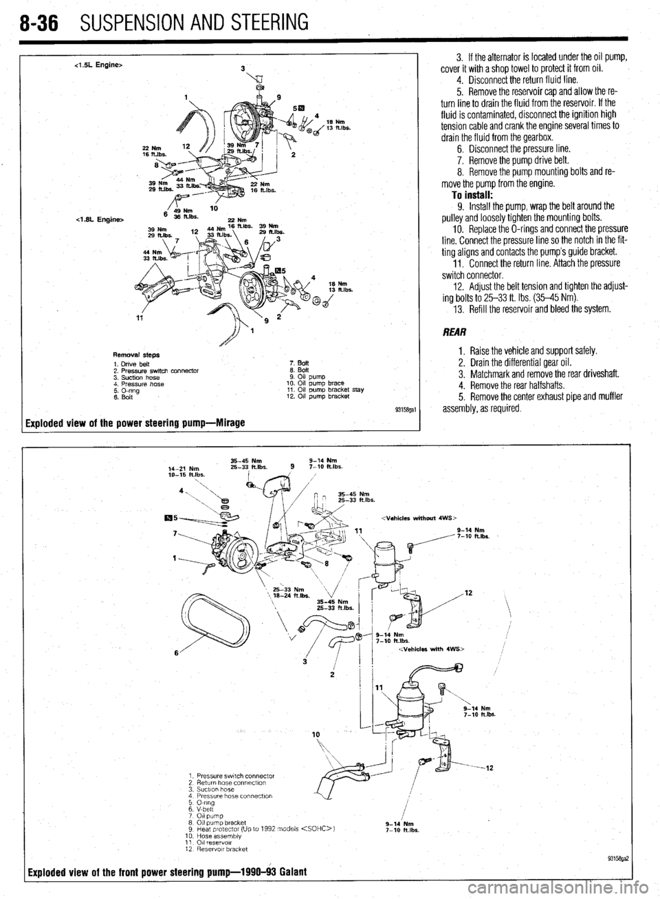
4 SL Engine>
<1.8L Engine>
Removal steps
1. Drive belt
7. BoIt
2. Pressure switch connector
8. Bolt
3. Suction hose
9. Oil pump
4. Pressure hose
10. Oil pump brace
2 Elrg
11. Oil pumo bracket stay
12. Oil pump bracket
93158gal
Exploded view of the power steering pump-Mirage
3. If the alternator is located under the oil pump,
cover it with a shop towel to protect it from oil.
4. Disconnect the return fluid line.
5. Remove the reservoir cap and allow the re-
turn line to drain the fluid from the reservoir. If the
fluid is contaminated, disconnect the ignition high
tension cable and crank the engine several times to
drain the fluid from the gearbox.
6. Disconnect the pressure line.
7. Remove the pump drive belt.
8. Remove the pump mounting bolts and re-
move the pump from the engine.
To install: 9. Install the pump, wrap the belt around the
pulley and loosely tighten the mounting bolts.
10. Replace the O-rings and connect the pressure
line. Connect the pressure line so the notch in the fit-
ting aligns and contacts the pump’s guide bracket.
1 I. Connect the return line. Attach the pressure
switch connector.
12. Adjust the belt tension and tighten the adjust-
ing bolts to 25-33 ft. Ibs. (35-45 Nm).
13. Refill the reservoir and bleed the system.
REAR
1. Raise the vehicle and support safely.
2. Drain the differential gear oil.
3. Matchmark and remove the rear driveshaft.
4. Remove the rear halfshafts.
5. Remove the center exhaust pipe and muffler
assembly, as required.
35-45 Nm 9-14 Nm
14-Z Nm 25-33 ft.lbs.
9 7-10 klbs.
2 g-lb Nm
7-10 ft.lbs.
Page 333 of 408
SUSPENSION AND STEERING 8-37
19-28 Nm
14-20 klbs.
/
12-18 Nm
9- 13 ft.lbs.
2rd
,
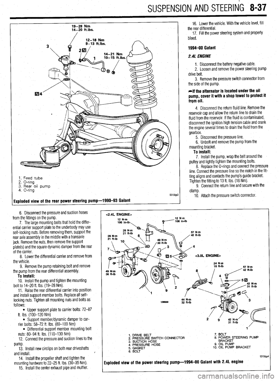
1. Feed tube
2. O-ring
3. Rear oil pump
4. O-ring
93158ga:
Exploded view of the rear power steering pump-1990-93 Galant
6. Disconnect the pressure and suction hoses
from the fittings on the pump.
7. The large mounting bolts that hold the differ-
ential carrier support plate to the underbody may use
self-locking nuts. Before removing them, support the
rear axle assembly in the middle with a transaxle
jack. Remove the nuts, then remove the support
plate(s) and the square dynamic damper from the rear
of the carrier.
8. Lower the differential carrier
and remove from
the vehicle.
9. Remove the pump retaining bolt and remove
the pump from the rear differential assembly.
To install: IO. Install the pump and tighten the mounting
bolt to 14-20 ft. Ibs. (19-28 Nm).
11. Raise the rear differential carrier into position
and install support member bolts. Replace all self-
locking nuts. Tighten all mounting nuts and bolts as
follows:
l Upper support plate to carrier bolts: 72-87
ft. Ibs. (100-120 Nm)
l Support member/dynamic damper to car-
rier bolts: 58-72 ft. Ibs. (80-100 Nm)
l Differential support member mounting bolt
nuts: 80-94 ft. Ibs. (110-130 Nm)
12. Connect the pressure and suction lines to the
pump.
13. Install new circlips on both rear driveshafts
and install. I
14.
Install the propeller shaft and tighten the
mounting hardware to 22-25 ft. Ibs. (30-35 Nm).
15. Install the center exhaust pipe and muffler.
1
16. Lower the vehicle. With the vehicle level, fill
the rear differential.
17. Fill the power steering system and properly
bleed.
1994-00 Galant
2.4L ENGINE
1. Disconnect the battery negative cable.
2. Loosen and remove the power steering pump
drive belt.
3. Remove the pressure switch connector from
the side of the pump.
*If the alternator is located under the oil
pump, cover it with a shop towel to protect it
frqm oil.
4. Disconnect the return fluid line. Remove the
reservoir cap and allow the return line to drain the
fluid from the reservoir. If the fluid is contaminated,
disconnect the ignition high tension cable and crank
the engine several times to drain the fluid from the
gearbox.
5. Disconnect the pressure line.
6. Unbolt and remove the pump from the
mounting bracket.
To install: 7. Install the pump, wrap the belt around the
pulley and lightly tighten the mounting bolts.
8. Replace the O-rings and connect the pressure
line. Connect the pressure line so the notch in the fit-
ting aligns and contacts the pump’s guide bracket.
Tighten the fitting to 13 ft. Ibs. (18 Nm).
9. Connect the return line and secure with the
clamp.
IO. Attach the pressure switch connector.
<2.4L ENGINE> 12 N-m 12 N-m
<3.OL ENGINE>
32 ft-lb
1. DRIVE BELT
2. PRESSURE SWITCH CONNECTOR
3. SUCTION HOSE
; i’;;‘;;RE HOSE 7. BOLT
8. ~O~~~E;TEER’NG PUMP
9. OIL PUMP
10. OIL PUMP BRACKET
6. BOLT
93158gal
Exploded view of the power steering pump-1994-00 Galant with 2.4L engine
Page 334 of 408
- 8-38 SUSPENSION AND STEERING
11. Adjust the power steering belt for proper ten-
sion and tighten the adjusting bolts.
12. Reconnect the negative battery cable.
13. Refill the reservoir and bleed the system.
3. Of EIJGINE
1. Disconnect the battery negative cable. 2. Disconnect the return fluid line. Remove the
reservoir cap and allow the return line to drain the
fluid from the reservoir. If the fluid is contaminated,
disconnect the ignition high tension cable and crank
the engine several times to drain the fluid from the
gear box.
3. Remove the power steering pump drive belt.
4. Remove the pressure switch connector from
the side of the pump.
5. If the alternator is located under the oil pump,
cover it with a shop towel to protect it from oil.
6. Disconnect the high pressure hose and the
return hose from the pump.
7. Remove the pump drive belt and unbolt the
pump from its bracket and remove the pump.
To install: 8. Install the pump, *rap the belt around the
pulley and tighten the bolts that secure the pump to
17 ft. Ibs. (24 Nm).
9. Replace the O-rings and connect the high
pressure hose. Connect the pressure line so the
notch in the fitting aligns and contacts the pump’s
guide bracket. Tighten the mounting nut with lock-
washer to 17 ft. Ibs. (24 Nm).
IO. Using a new hose clamp, connect the return
line.
11. Attach the pressure switch connector.
12. Adjust the belt tension and tighten the
adjust- ing bolts.
13. Refill the reservoir and bleed the system.
Diamante *
FRONT
. 1. Disconnect the battery negative cable. 2. Disconnect the return fluid line. Remove the
reservoir cap and allow the return line to drain the
fluid from the reservoir. If the fluid is contaminated,
disconnect the ignition high tension cable and crank
the engine several times to drain the fluid from the
gearbox.
3. Remove the power steering pump drive belt.
4. Remove the pressure switch connector from
the side of the pump.
5. If the alternator is located under the oil pump,
cover it with a shop towel to protect it from oil.
6. Disconnect the high pressure hose and the
return hose from the pump.
7. Remove the pump drive belt and unbolt the
pump from its bracket and remove the pump.
To install: 8. Install the pump, wrap the belt around the
pulley and tighten the bolts that secure the pump to
17 ft. Ibs. (24 Nm).
9. Replace the O-rings and connect the high
pressure hose. Connect the pressure line so the
notch in the fitting aligns and contacts the pump’s
guide bracket. Tighten the mounting nut with lock-
washer to 17 ft. Ibs. (24 Nm).
10. Using a new hose clamp, connect the return
line.
Il. Attach the pressure switch connector.
12. Adjust the belt tension and tighten the adjust-
ing bolts.
13. Refill the reservoir and bleed the system.
REAR
1. Disconnect the negative battery cable.
2. Drain the power steering fluid.
3. Remove the rear power steering pump heat
protector, located on the engine side of the differen-
tial on the transaxle.
4. Disconnect the pressure line from the pump.
5. Disconnect the suction hose from the pump.
6. Remove the mounting bolts and remove the
pump from the transaxle.
44
33
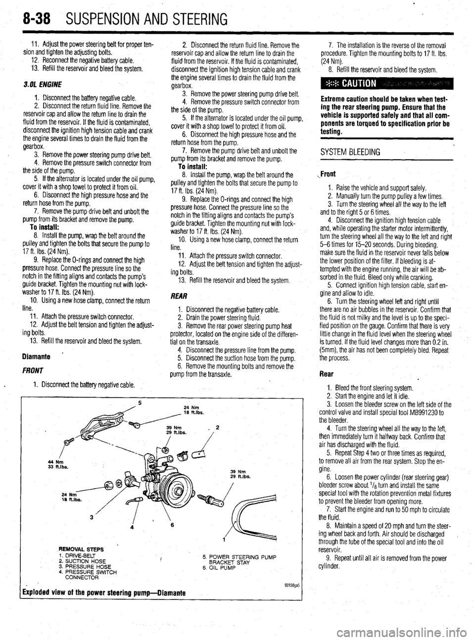
REMOVAL STEPS
5. POWER STEERING PUMP
BRACKET STAY
6. OIL PUMP 1. DRIVE-BELT
2. SUCTION HOSE I ’ 3. PRESSURE HOSE
4. PRESSURE SWITCH
CONNECTOR
Exploded view of the power steering pump-Diamante
. 93158ga5
7. The installation is the reverse of the removal
procedure. Tighten the mounting bolts to 17 ft. Ibs.
(24 Nm).
8. Refill the reservoir and bleed the system.
Extreme caution should be taken when test-
ing the rear steering pump. Ensure that the
vehicle is supported safely and that all com-
ponents are torqued to specification prior be
testing.
. SYSTEM BLEEDING
,Front
1. Raise the vehicle and support safely.
2. Manually turn the pump pulley a few times.
3. Turn the steering wheel all the way to the left
and to the right 5 or 6 times.
4. Disconnect the ignition high tension cable
and, while operating the starter motor intermittently,
turn the steering wheel all the way to the letI and right
5-6 times for 15-20 seconds. During bleeding,
make sure the fluid in the reservoir never falls below
the lower position of the filter. If bleeding is at-
tempted with the engine running, the air will be ab-
sorbed in the fluid. Bleed only while cranking.
5. Connect ignition high tension cable, start en-
gine and allow to idle.
6. Turn the steering wheel left and right until
there are no air bubbles in the reservoir. Confirm that
the fluid is not milky and the level is up to the speci-
fied position on the gauge. Confirm that there is very
little change in the fluid level when the steering wheel
is turned. If the fluid level changes more than 0.2 in.
(5mm), the air has not been completely bled. Repeat
the process.
Rear
.
1. Bleed the front steering system.
2. Start the engine and let it idle.
3. Loosen the bleeder screw on the left side of the
control valve and install special tool MB991230 to
the bleeder.
4. Turn the steering wheel all the way to the left,
then immediately turn it halfway back. Confirm that
air has discharged with the fluid.
5. Repeat Step 4 two or three times as required,
to remove all air from the rear system. Stop the en-
gine.
6. Loosen the power cylinder (rear steering gear)
bleeder screw about I/* turn and install the same
special tool with the rotation prevention metal fixtures
to prevent the bleeder from opening more.
7. Start the engine and run to 50 mph to circulate
the fluid.
8. Maintain a speed of 20 mph and turn the steer-
ing wheel back and forth. Air should be discharged ,
through the tube of the special tool and into the oil
reservoir.
9. Repeat until all air is removed from the power
cylinder.
Page 335 of 408
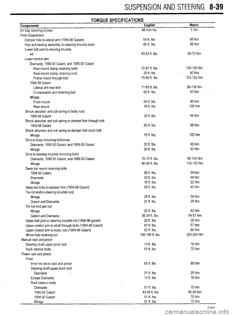
SUSPENSION AND STEERliG 8-39
Components
Air bag retaining screws TORQUE SPECIFICATIONS English
48 inch Ibs. Metric
5Nm
Front Suspension
Damper fork-to-lateral arm (1994-98 Galant)
Hub and bearing assembly-to-steering knuckle bolts
Lower ball joint-to-steering knuckle
I
All
Lower control arm
Diamante, 1990-93 Galant, and 1999-00 Galant
Rear mount clamp retaining bolts
Rear mount clamp retaining nuts
Frame mount through bolt
1994-98 Galant
Lateral arm rear bolt
Compression arm retaining bolt
Mirage
Front mount
Rear mount
Shock absorber and coil spring-to-body nuts
1994-98 Galant
Shock absorber and coil spring-to-damper fork through bolt
1994-98 Galant
Shock absorber and coil spring-to-damper fork pinch bolt
Mirage
Strut-to-body mounting bolts/nuts
Diamante, 1990-93 Galant, and 1999-00 Galant
Mirage
Strut-to-steering knuckle mounting bolts
Diamante, 1990-93 Galant, and 1999-00 Galant
Mirage
Sway bar mount retaining bolts
1994-00 Galant
Diamante
Mirage
Sway bar links-to-damper fork (1994-98 Galant)
Tie-rod end-to-steering knuckle nuts
Mirage
Galant and Diamante
Tie rod end jam nut
Mirage
. Galant and Diamante
Upper ball joint-to-steering knuckle nut (1994-98 galant)
Upper control arm-to-shaft through bolts (1994-98 Galant)
Upper control arm-to-body nuts (1994-98 Galant)
Wheel hub retaining nut
Manual rack and pinion
Steering shaft upper pinch bolt
Rack retainer bolts
Power rack and pinion
Front
Inner tie rod-to-rack and pinion
Steering shaft upper pinch bolt
Diamante I
Except Diamante
Rack retainer bolts
Diamante
1990-93 Galant
1994-00 Galant . 64 ft. Ibs.
65 ft. Ibs.
43-52 ft. Ibs.
72-87 ft. Ibs.
29 ft. Ibs.
75-90 ft. Ibs.
71-85 ft Ibs.
60 ft. Ibs.
65 ft. tbs.
78 ft. Ibs.
32 ft. Ibs.
65 ft. Ibs.
76 ft. Ibs.
33
ft. tbs. 29 ft. Ibs.
70-76 ft. Ibs.
80-94 ft. Ibs.
28 ft. Ibs.
32 ft. Ibs.
16 ft. Ibs.
29 ft. Ibs
25 ft. Ibs.
21 ft. Ibs.
30 ft. tbs.
36-39 ft. Ibs.
20 ft. Ibs.
41 ft. Ibs.
62 ft. Ibs.
145-188 ft. Ibs.
13 ft. Ibs.
51 ft. lbs.
65 ft. Ibs.
21 fta Ibs.
13 ft. Ibs.
51 ft. Ibs.
43-58 ft. Ibs
51 ft. Ibs. 88 Nm
88 Nm
60-72 Nm
100-120 Nm
40 Nm
102-l 22 Nm
98-l 18 Nm
83 Nm
90Nm
108 Nm
44 Nm
88 Nm
103 Nm
45 Nm
40 Nm
90-105 Nm
110-130 Nm
39 Nm
44 Nm
22 Nm
40 Nm
34 Nm
29 Nm
42 Nm
49-53 Nm
28 Nm
57 Nm
86 Nm
200-260 Nm
18Nm
70 Nm
88 Nm
29 Nm
l8Nm
70Nm -
60-80 Nm
70 Nm
70 Nm
93158cOl
Mirage 51 ft. Ibs.
Page 336 of 408
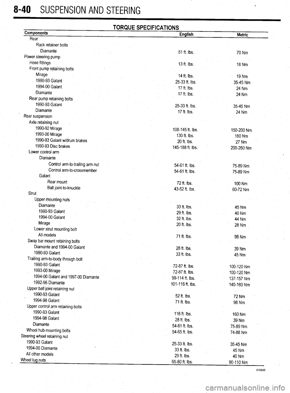
8-40 SUSPENSION AND STEERING
Components
Rear TORQUE SPECIFICATIONS English
Metric
Rack retainer bolts
Control arm-to-trailing arm nut Diamante
Power steering pump
Hose fittings
Front pump retaining bolts
Mirage
1990-93 Galant
1994-00 Galant
Diamante
Rear pump retaining bolts
1990-93 Galant
Diamante
Rear suspension
Axle retaining nut
1990-92 Mirage
1993-00 Mirage
1990-93 Galant w/drum brakes
1990-93 Disc brakes
Lower control arm
Diamante 51 ft. Ibs
13 ft. Ibs,
14 ft. Ibs.
25-33 ft. tbs.
17 ft. tbs.
17 ft. Ibs.
25-33 ft. Ibs.
17 ft. Ibs.
108-145 ft. Ibs.
130 ft. Ibs.
20 ft. Ibs.
145-188 ft. Ibs.
54-61 ft. Ibs. 54-61 ft. Ibs.
72 ft. Ibs.
43-52 ft. Ibs.
33 ft. Ibs.
29 ft. Ibs.
32 ft. Ibs.
20 ft. Ibs.
71 ft. Ibs.
28 ft. Ibs.
33 ft. tbs.
72-87 ft. Ibs.
72-87 ft. Ibs.
99414 ft. Ibs.
101-116 ft. Ibs.
52 ft. Ibs.
71 ft. Ibs.
116 ft. Ibs.
28 ft. Ibs.
54-61 ft. Ibs.
54-65 ft. Ibs.
25-33 ft. Ibs.
33 ft. Ibs.
29 ft Ibs.
65-80 ft. Ibs. Control arm-to-crossmember
Galant
Rear mount
Ball joint-to-knuckle
Strut
Upper mounting nuts
Diamante
1990-93 Galant
1994-00 Galant
Mirage
Lower strut mounting bolt
All models
Sway bar mount retaining bolts
Diamante and 1994-00 Galant
1990-93 Galant
Trailing arm-to-body through bolt
1990-93 Galant
1993-00 Mirage
1994-00 Galant and 1997-00 Diamante
1992-96 Diamante
Upper ball joint retaining nut
1990-93 Galant
1994-98 Galan t
Upper control arm retaining bolts
1990-93 Galant
1994-98 Galant
Diamante
Wheel hub mounting bolts
Steering wheel retaining nut
1990-93 Galant
1994-00 Diamante
All other models 70 Nm
18 Nm
19 Nm
35-45 Nm
24 Nm
24 Nm
35-45 Nm
24 Nm
150-200 Nm
180 Nm
27 Nm
200-260 Nm
75-89 Nm
75-89 Nm
100 Nm
60-72 Nm
45 Nm
40 Nm
44 Nm
28 Nm
98 Nm
39 Nm
45 Nm
100-120 Nm
100-120 Nm
137-157 Nm
140-160 Nm
72Nm *
98 Nm
160 Nm
39 Nm
75-89 Nm
74-88 Nm
35-45 Nm
45 Nm
40 Nm
90-l IO Nm
93158co2
Wheel lug nuts
Page 337 of 408
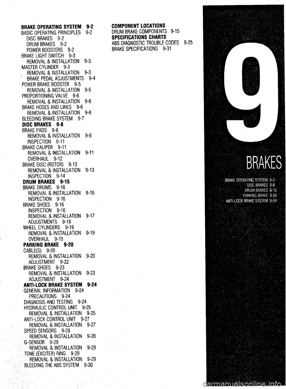
BRAKE OPERATING SYSTEM 9-2
BASIC OPERATING PRINCIPLES 9-2
DISC BRAKES 9-2
DRUM BRAKES 9-2
POWERBOOSTERS 9-2
BRAKE LIGHT SWITCH 9-3
REMOVAL&INSTALLATION 9-3
MASTER CYLINDER 9-3
REMOVAL&INSTALLATION 9-3
' BRAKE PEDAL ADJUSTMENTS 9-4
POWER BRAKEBOOSTER 9-5
REMOVAL &INSTALLATION 9-5
PROPORTIONING VALVE 9-6
REMOVAL &INSTALLATION 9-6
BRAKEHOSESAND LINES 9-6
REMOVAL&INSTALLATION 9-6
BLEEDING BRAKESYSTEM 9-7
DISC BRAKES 9-8
BRAKE PADS 9-8
REMOVAL &INSTALLATION 9-8
INSPECTION 9-11
BRAKE CALIPER 9-11
REMOVAL & INSTALLATION 9-11
OVERHAUL 9-12
BRAKE DISC (ROTOR) 9-13
REMOVAL &INSTALLATION 9-13
INSPECTION 9-14
DRUM BRAKES 9-15
BRAKEDRUMS 9-16
REMOVAL &INSTALLATION 9-16
INSPECilON 9-16
BRAKESHOES 9-16
INSPECTION 9-16
REMOVAL&INSTALLATION 9-17
ADJUSTMENTS 9-18
WHEELCYLINDERS 9-19
REMOVAL &INSTALLATION 9-19
. OVERHAUL 9-19
PARKING BRAKE 9-20
CABLE(S) 9-20
REMOVAL&INSTALLATION 9-20
ADJUSTMENT 9-22
BRAKESHOES 9-23
REMOVAL &INSTALLATION 9-23
ADJUSTMENT 9-24
ANTI-LOCKBRAKE SYSTEM 9-24
GENERAL INFORMATION 9-24
PRECAUTIONS 9-24
DIAGNOSIS AND TESTING 9-24
HYDRAULIC CONTROL UNIT 9-25
REMOVAL&INSTALLATION 9-25
ANTI-LOCK CONTROL UNIT 9-27
REMOVAL&INSTALLATION 9-27
SPEED SENSORS 9-28
REMOVAL &INSTALLATION 9-28
b G-SENSOR 9-29
REMOVAL &INSTALLATION 9-29
' TONE (EXCITER) RING 9-29
REMOVAL&INSTALLATION 9-29
BLEEDINGTHEABSSYSTEM 9-30 COMPONENTLOCATIONS
DRUM BRAKECOMPONENTS 9-15
SPECIFICATIONS CHARTS
ABS DIAGNOSTICTROUBLE CODES 9-25
BRAKE SPECIFICATIONS 9-31
Page 338 of 408
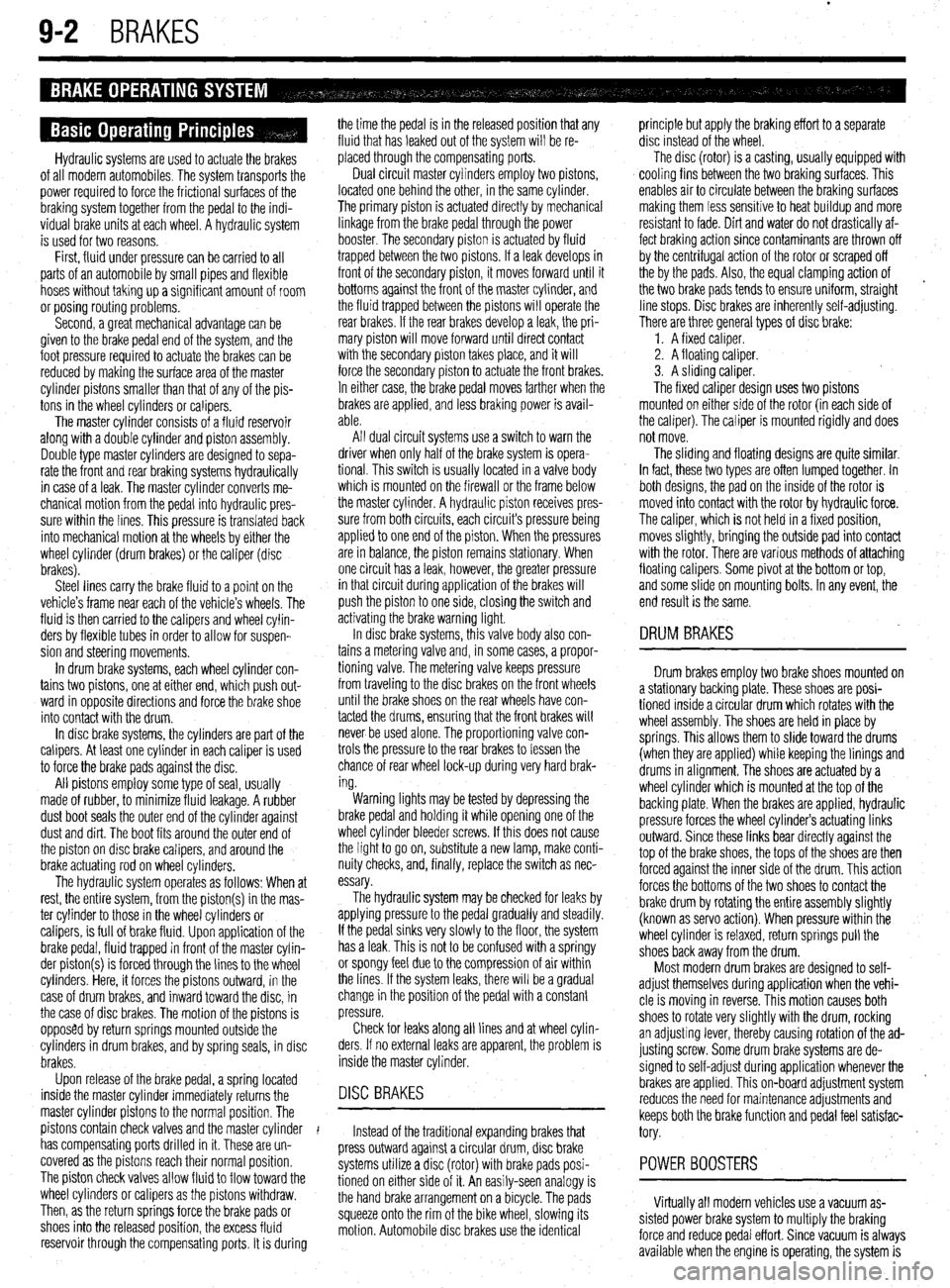
9-2 BRAKES
Hydraulic systems are used to actuate the brakes
of all modern automobiles. The system transports the
power required to force the frictional surfaces of the
braking system together from the pedal to the indi-
vidual brake units at each wheel. A hydraulic system
is used for two reasons.
First, fluid under pressure can be carried to all
parts of an automobile by small pipes and flexible
hoses without taking up a significant amount of room
or posing routing problems.
Second, a great mechanical advantage can be
given to the brake pedal end of the system, and the
foot pressure required to actuate the brakes can be
reduced by making the surface area of the master
cylinder pistons smaller than that of any of the pis-
tons in the wheel cylinders or calipers.
The master cylinder consists of a fluid reservoir
along with a double cylinder and piston assembly.
Double type master cylinders are designed to sepa-
rate the front and rear braking systems hydraulically
in case of a leak. The master cylinder converts me-
chanical motion from the pedal into hydraulic pres-
sure within the lines. This pressure is translated back
into mechanical motion at the wheels by either the
wheel cylinder (drum brakes) or the caliper (disc
brakes).
Steel lines carry the brake fluid to a point on the
vehicle’s frame near each of the vehicle’s wheels. The
fluid is then carried to the calipers and wheel cylin-
ders by flexible tubes in order to allow for suspen-
sion and steering movements.
In drum brake systems, each wheel cylinder con-
tains two pistons, one at either end, which push out-
ward in opposite directions and force the brake shoe
into contact with the drum.
In disc brake systems, the cylinders are part of the
calipers. At least one cylinder in each caliper is used
to force the brake pads against the disc.
All pistons employ some type of seal, usually
made of rubber, to minimize fluid leakage. A rubber
dust boot seals the outer end of the cylinder against
dust and dirt. The boot fits around the outer end of
the piston on disc brake calipers, and around the
brake actuating rod on wheel cylinders.
The hydraulic system operates as follows: When at
rest, the entire system, from the piston(s) in the mas-
ter cylinder to those in the wheel cylinders or
calipers, is full of brake fluid. Upon application of the
brake pedal, fluid trapped in front of the master cylin-
der piston(s) is forced through the lines to the wheel
cylinders. Here, it forces the pistons outward, in the
case of drum brakes, and inward toward the disc, in
the case of disc brakes. The motion of the pistons is
opposed by return springs mounted outside the
cylinders in drum brakes, and by spring seals, in disc
brakes.
Upon release of the brake pedal, a spring located
inside the master cylinder immediately returns the
master cylinder pistons to the normal position. The
pistons contain check valves and the master cylinder
I
has compensating ports drilled in it. These are un-
covered as the pistons reach their normal position.
The piston check valves allow fluid to flow toward the
wheel cylinders or calipers as the pistons withdraw.
Then, as the return springs force the brake pads or
shoes into the released position, the excess fluid
reservoir through the compensating ports. It is during the time the pedal is in the released position that any
fluid that has leaked out of the system will be re-
placed through the compensating ports.
Dual circuit master cylinders employ two pistons,
located one behind the other, in the same cylinder.
The primary piston is actuated directly by mechanical
linkage from the brake pedal through the power
booster. The secondary piston is actuated by fluid
trapped between the two pistons. If a leak develops in
front of the secondary piston, it moves forward until it
bottoms against the front of the master cylinder, and
the fluid trapped between the pistons will operate the
rear brakes. If the rear brakes develop a leak, the pri-
mary piston will move forward until direct contact
with the secondary piston takes place, and it will
force the secondary piston to actuate the front brakes.
In either case, the brake pedal moves farther when the
brakes are applied, and less braking power is avail-
able.
All dual circuit systems use a switch to warn the
driver when only half of the brake system is opera-
tional. This switch is usually located in a valve body
which is mounted on the firewall or the frame below
the master cylinder. A hydraulic piston receives pres-
sure from both circuits, each circuits pressure being
applied to one end of the piston. When the pressures
are in balance, the piston remains stationary. When
one circuit has a leak, however, the greater pressure
in that circuit during application of the brakes will
push the piston to one side, closing the switch and
activating the brake warning light.
In disc brake systems, this valve body also con-
tains a metering valve and, in some cases, a propor-
tioning valve. The metering valve keeps pressure
from traveling to the disc brakes on the front wheels
until the brake shoes on the rear wheels have con-
tacted the drums, ensuring that the front brakes will
never be used alone. The proportioning valve con-
trols the pressure to the rear brakes to lessen the
chance of rear wheel lock-up during very hard brak-
ing.
Warning lights may be tested by depressing the
brake pedal and holding it while opening one of the
wheel cylinder bleeder screws. If this does not cause
the light to go on, substitute a new lamp, make conti-
nuity checks, and, finally, replace the switch as nec-
essary.
The hydraulic system may
be checked for leaks by applying pressure to the pedal gradually and steadily.
If the pedal sinks very slowly to the floor, the system
has a leak. This is not to be confused with a springy
or spongy feel due to the compression of air within
the lines. If the system leaks, there will be a gradual
change in the position of the pedal with a constant
pressure.
Check for leaks along all lines and at wheel cylin-
ders. If no external leaks are apparent, the problem is
inside the master cylinder,
DISC BRAKES
Instead of the traditional expanding brakes that
press outward against a circular drum, disc brake
systems utilize a disc (rotor) with brake pads posi-
tioned on either side of it. An easily-seen analogy is
the hand brake arrangement on a bicycle. The pads
squeeze onto the rim of the bike wheel, slowing its
motion. Automobile disc brakes use the identical principle but apply the braking effort to a separate
disc instead of the wheel.
The disc (rotor) is a casting, usually equipped with
cooling fins between the two braking surfaces. This
enables air to circulate between the braking surfaces
making them less sensitive to heat buildup and more
resistant to fade. Dirt and water do not drastically af-
fect braking action since contaminants are thrown off
by the centrifugal action of the rotor or scraped off
the by the pads. Also, the equal clamping action of
the two brake pads tends to ensure uniform, straight
line stops. Disc brakes are inherently self-adjusting.
There are three general types of disc brake:
1. A fixed caliper.
2. A floating caliper.
3. A sliding caliper.
The fixed caliper design uses two pistons
mounted on either side of the rotor (in each side of
the caliper). The caliper is mounted rigidly and does
not move.
The sliding and floating designs are quite similar.
In fact, these two types are often lumped together. In
both designs, the pad on the inside of the rotor is
moved into contact with the rotor by hydraulic force.
The caliper, which is not held in a fixed position,
moves slightly, bringing the outside pad into contact
with the rotor. There are various methods of attaching
floating calipers. Some pivot at the bottom or top,
and some slide on mounting bolts. In any event, the
end result is the same.
DRUM BRAKES
Drum brakes employ two brake shoes mounted on
a stationary backing plate. These shoes are posi-
tioned inside a circular drum which rotates with the
wheel assembly. The shoes are held in place by
springs. This allows them to slide toward the drums
(when they are applied) while keeping the linings and
drums in alignment. The shoes are actuated by a
wheel cylinder which is mounted at the top of the
backing plate. When the brakes are applied, hydraulic
pressure forces the wheel cylinder’s actuating links
outward. Since these links bear directly against the
top of the brake shoes, the tops of the shoes are then
forced against the inner side of the drum. This action
forces the bottoms of the two shoes to contact the
brake drum by rotating the entire assembly slightly
(known as servo action). When pressure within the
wheel cylinder is relaxed, return springs pull the
shoes back away from the drum.
Most modern drum brakes are designed to self-
adjust themselves during application when the vehi-
cle is moving in reverse. This motion causes both
shoes to rotate very slightly with the drum, rocking
an adjusting lever, thereby causing rotation of the ad-
justing screw. Some drum brake systems are de-
signed to self-adjust during application whenever the
brakes are applied. This on-board adjustment system
reduces the need for maintenance adjustments and
keeps both the brake function and pedal feel satisfac-
tory.
POWER BOOSTERS
Virtually all modern vehicles use a vacuum as-
sisted power brake system to multiply the braking
force and reduce pedal effort. Since vacuum is always
available when the engine is operating, the system is
Page 339 of 408
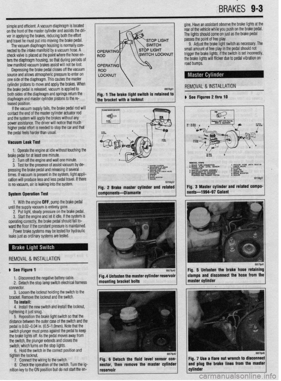
BRAKiS 9-3
simple and efficient. A vacuum diaphragm is located gine. Have an assistant observe the brake lights at the
on the front of the master cylinder and assists the dri- rear of the vehicle while you push on the brake pedal.
ver in applying the brakes, reducing both the effort The lights should come on just as the brake pedal
and travel he must put into moving the brake pedal. passes the point of free play.
The vacuum diaphragm housing is normally con- 9.
Adjust the brake light switch as necessary. The
netted to the intake manifold by a vacuum hose. A small amount of free play in the
pedal should not
check valve is placed at the point where the hose en-
ters the diaphragm housing, so that during periods
Of low manifold vacuum brakes assist will not be lost.
Depressing the brake pedal closes off the vacuum
source and allows atmospheric pressure to enter on
one side of the diaphragm. This causes the master
cylinder pistons to move and apply the brakes. When
the brake pedal is released, vacuum is applied to
REMOVAL &INSTALLATION
both sides of the diaphragm and springs return the
diaphragm and master cylinder pistons to the re- ) See Figures 2 thru 10
leased position.
If the vacuum supply fails, the brake pedal rod will
contact the end of the master cylinder actuator rod
and the system will apply the brakes without any
power assistance. The driver will notice that much
higher pedal effort is needed to stop the car and that
the pedal feels harder than usual.
Vacuum leak Test
1. Operate the engine at idle without touching the
brake pedal for at least one minute.
2. Turn off the engine and wait one minute.
3. Test for the presence of assist vacuum by de-
pressing the brake pedal and releasing it several
3 MASTER N- 188A11Ly
times. If vacuum is present in the system, light appli- . KLNsIMEm 0s CLWRANCE
BETWEEN BRAKE WOSTER
cation will produce less and less pedal travel. If there PUSHROO AN0 PRIMARY PISTCU
is no vacuum, air is leaking into the system.
System Operation Test
1. With the engine OFF, pump the brake pedal
until the supply vacuum is entirely gone.
2. Put light, steady pressure on the brake pedal.
3. Start the engine and let it idle. If the system is
operating correctly, the brake pedal should fall to-
ward the floor if the constant pressure is maintained.
Power brake systems may be tested for hydraulic
leaks just as ordinary systems are tested.
REMOVAL&INSTALLATION
$ See Figure 1
1. Disconnect the negative battery cable.
2. Detach the stop lamp switch electrical harness
connector.
3. Loosenthe locknut holding the switch to the
bracket. Remove the locknut and the switch.
To install:
4.
Install the new switch and install the locknut,
tightening it just snug.
5. Reposition the brake light switch so that the
distance between the outer case of the switch and the
pedal is 0.02-0.04 in. (0.5-l .Omm). Note that the
switch plunger must press against the pedal to keep
the brake lights off. As the pedal moves away from
the switch, the plunger extends and closes the
switch, which turns on the stop lights.
6.
Hold the switch in the correct position and
tighten the locknut.
7. Connect the wiring to the switch.
8. Check the operation of the switch. Turn the ig-
nition key to the ON position but do not start the en-
Page 340 of 408
9-4 BRAKES
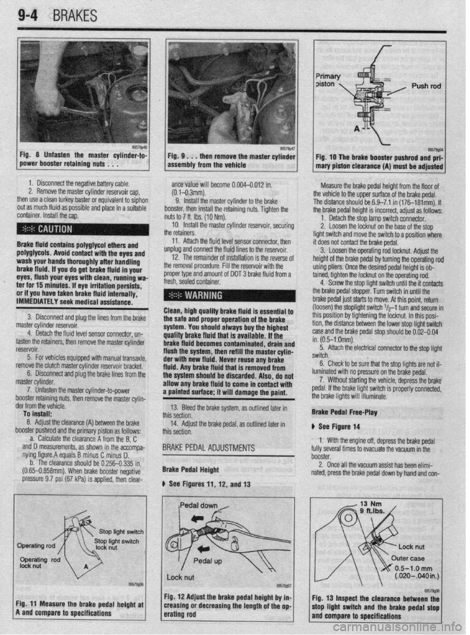
Fig 8 Unfasten the master cylinder-to-
power booster retaining nuts . . . F57g’6~ Fig. 9 . . . then remove the master cylinder
assembly from the vehicle Fig. 10 The brake booster pushrod and prf-
mary piston clearance (A) must be adjusted
1. Disconnect the negative battery cable.
2. Remove the master cylinder reservoir cap,
then use a clean turkey baster or equivalent to siphon
out as much fluid as possible and place in a suitable
container. Install the cap.
Brake fluid contains polyglycol ethers and
polyglycols. Avoid contact with the eyes and
wash your hands thoroughly after handling
brake fluid. If you do get brake fluid in your
eyes, flush your eyes with clean, running wa-
ter for 15 minutes. If eye irritation persists,
or if you have taken brake fluid internally,
IMMEDIATELY seek medical assistance.
3. Disconnect and plug the lines from the brake
master cylinder reservoir.
4. Detach the fluid level sensor connector, un-
fasten the retainers, then remove the master cylinder
reservoir.
5. For vehicles equipped with manual transaxle,
remove the clutch master cylinder reservoir bracket.
6. Disconnect and plug the brake lines from the
master cylinder.
7. Unfasten the master cylinder-to-power
booster retainino nuts, then remove the master cvlin- ante value will become 0.004-0.012 in.
(0.1-0.3mm).
9. install the master cylinder to the brake
booster, then install the retaining nuts. Tighten the
nuts to 7 ft. Ibs. (10 Nm).
10. Install the master cylinder reservoir, securing
the retainers.
11. Attach the fluid level sensor connector, then
unplug and connect the fluid lines to the reservoir.
12. The remainder of installation is the reverse of
the removal procedure. Fill the reservoir with the
proper type and amount of DOT 3 brake fluid from a
fresh, sealed container.
I l
Clean, high quality brake fluid is essential to
the safe and proper operation of the brake
system. You should always buy the highest
quality brake fluid that is available. If the
brake fluid becomes contaminated, drain and
flush the system, then refill the master cylin-
der with new fluid. Never reuse any brake
fluid. Any brake fluid that is removed from
the system should be discarded. Also, do not
allow any brake fluid to come in contact with
a painted surface; it will damage the paint. Measure the brake pedal height from the floor of
the vehicle to the upper surface of the brake pedal.
The distance should be 6.9-7.1 in (176181mm). If
the brake pedal height is incorrect, adjust as follows:
1. Detach the stop lamp switch connector.
2. Loosen the locknut on the base of the stop
light switch and move the switch to a position where
it does not contact the brake pedal.
3. Loosen the operating rod locknut. Adjust the
height of the brake pedal by turning the operating rod
using pliers. Once the desired pedal height is ob-
tained, tighten the locknut on the operating rod.
4. Screw the stop light switch until the it contacts
the brake pedal stopper. Turn switch in until the
brake pedal just starts to move. At this point, return
(loosen) the stoplight switch $-1 turn and secure in
this position by tightening the locknut. In this posi-
tion, the distance between the lower stop light switch
case and the brake pedal stop should be 0.02-0.04
in. (0.5-l .Omm).
5. Attach the electrical connector to the stop light
switch.
6. Check to be sure that the stop lights are not il-
luminated with no pressure on the brake pedal.
7. Without starting the vehicle, depress the brake
pedal. If the brake light switch is properly connected,
the brake lights will illuminate.
der from the vefiicle.
To install:
8. Adjust the clearance (A)
booster pushrod ant
a. Calculate tl -,
between the brake
I the primary piston as follows:
le clearance A from the B, C
accompa-
i D.
I.335 in.
negative and D measurements, as shown in the
nying figure.A equals B minus C minus
b. The clearance should be 0.256-t
(0.65-0.858mm). When brake booster I
pressure 9.7 psi (67 kPa) is applied, then clear- 13. Bleed the brake system, as outlined later in
this section.
14. Adjust the brake pedal, as outlined later in
this section.
BRAKE PEDAL ADJUSTMENTS
Brake Pedal Height
b See Figures 11, 12, and 13 Brake Pedal Free-Play
II See Figure 14
1. With the engine off, depress the brake pedal
fully several times to evacuate the vacuum in the
booster.
2. Once all the vacuum assist has been elimi-
nated, press the brake pedal down by hand and con-
/
0.5-1.0 mm (.020-B40in.J I
I
I I
Fig. 12 Adjust the brake pedal height by in- I I.
@57w
Cir 44 “a*., .._^ *I.- 9.--l,- ---I-* L-@-L. -I Fig. 13 Inspect the clearance between thf . . - _-.L -*.a- - . . * _ . . . . ._ . rly. I I rnca~urc we urime peoai nefgnr ar
A and compare to specifications creasmg or aecreasing the lengrn or me op-
erating rod mop llgnt WItCh arm the brake pedal stop
and compare to specifications