MITSUBISHI ECLIPSE 1990 Service Manual
Manufacturer: MITSUBISHI, Model Year: 1990, Model line: ECLIPSE, Model: MITSUBISHI ECLIPSE 1990Pages: 391, PDF Size: 15.27 MB
Page 281 of 391
AUTOMATIC TRANSAXLE - Transaxle Control21-57
-7.To torque convert,erLine pressure
’Pump(from oil pump) suction
1 To N-RI control valveLine pressure
(from oil pump)1750072
-#5
To N-Dcontrol
valve
To toraueconverter
AdjLine pressure
1+(from oil pump)Pumpsuction
1 ~7valve
To N-Dcontrol
valve
s
Line pressure
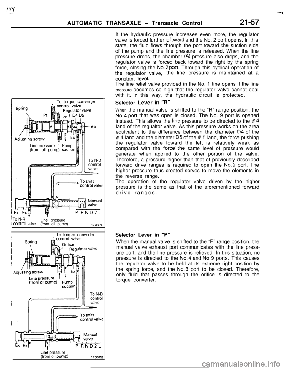
(from oil pump)If the hydraulic pressure increases even more, the regulator
valve is forced further leftward and the No. 2 port opens. In this
state, the fluid flows through the port toward the suction side
of the pump and the line pressure is released. When the line
pressure drops, the chamber
(A) pressure also drops, and the
regulator valve is forced back toward the right by the spring
force, closing the No.2
port. Through this cyclical operation of
the regulator valve,the line pressure is maintained at a
constant
tevel.The line relief valve provided in the No. 1 tine opens if the line
pressure becomes so high that the regulator valve cannot deal
with it.
In this way, the hydraulic circuit is protected.
Selector Lever in ‘R”
When the manual valve is shifted to the “R” range position, the
No.4 post that was open is closed. The No. 9 port is opened
instead. This allows the
tine pressure to be directed to the #4land of the regualtor valve. As this pressure works on the area
equivalent to the difference between the diameter
04 of the
# 4 land and the diameter 05 of the # 5 land, the force pushing
the regulator valve toward the left is relatively weak as
compared with the
force’the same level of pressure would
generate when applied to the other portion of the valve.
Therefore, a pressure higher than that of previously described
forward drive ranges is required to open the No.2 port. The
higher pressure thus created serves to move the elements in
the reverse range.
The operation of the regulator valve driven by the higher
pressure is the same as that of the aforementioned forward
drive ranges.
Selector Lever in
‘P”When the manual valve is shifted to the “P” range position, the
manual valve exhaust port communicates with the line press-
ure port, and the line pressure is relieved. In this situation, no
pressure is directed to the No.4 and No.9 ports. This causes
the regulator valve to be held at its extreme right position by
the spring force, and the No.3 port to be closed. Therefore,
only fluid that passes through the orifice is directed to the
torque converter.
Page 282 of 391
21-58AUTOMATIC TRANSAXLE - Transaxle Control
1750227
To torqueconverter
Pump suction
h& regulator
side1750081
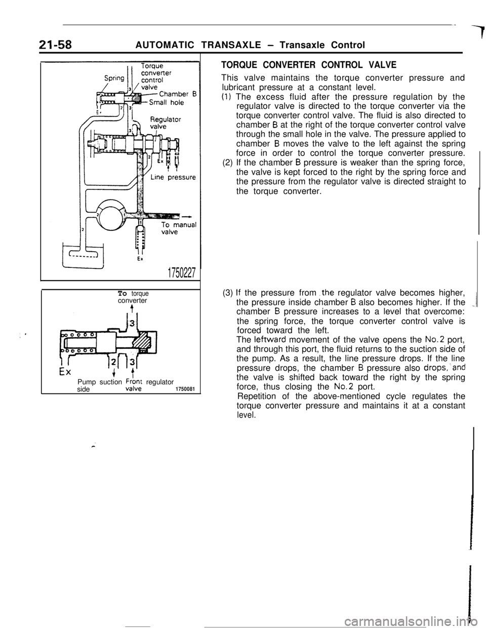
TORQUE CONVERTER CONTROL VALVEThis valve maintains the torque converter pressure and
lubricant pressure at a constant level.
(1) The excess fluid after the pressure regulation by the
regulator valve is directed to the torque converter via the
torque converter control valve. The fluid is also directed to
chamber
B at the right of the torque converter control valve
through the small hole in the valve. The pressure applied to
chamber
B moves the valve to the left against the spring
force in order to control the torque converter pressure.
(2) If the chamber
B pressure is weaker than the spring force,
the valve is kept forced to the right by the spring force and
the pressure from the regulator valve is directed straight to
the torque converter.
(3)
If the pressurefrom .the regulator valve becomes higher,
the pressure inside chamber
B also becomes higher. If the_1chamber B pressure increases to a level that overcome:
the spring force, the torque converter control valve is
forced toward the left.
The leftward movement of the valve opens the No.2 port,
and through this port, the fluid returns to the suction side of
the pump. As a result, the line pressure drops. If the line
pressure drops, the chamber
B pressure also drops,‘and
the valve is shifted back toward the right by the spring
force, thus closing the No.2 port.
Repetition of the above-mentioned cycle regulates the
torque converter pressure and maintains it at a constant
level.
Page 283 of 391
/ii>--..AUTOMATIC TRANSAXLE
- Transaxle Control21-59
Sxxrolvalve175022E
6
LmeFrom
TooilFrompressure torque- pump 2;0%conver-
termntrd
valveDAMPER CLUTCH CONTROL VALVE AND DAMPER
CLUTCH CONTROL SOLENOID VALVE
Damper Clutch Control Valve
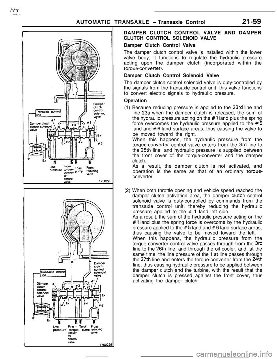
The damper clutch control valve is installed within the lower
valve body; it functions to regulate the hydraulic pressure
acting upon the damper clutch (incorporated within thetorqueconverter).
Damper Clutch Control Solenoid Valve
The damper clutch control solenoid valve is duty-controlled by
the signals from the transaxle control unit; this valve functions
to convert electric signals to hydraulic pressure.
Operation
(1) Because reducing pressure is applied to the
23rd line and
line
23a when the damper clutch is released, the sum of
the hydraulic pressure acting on the
# 1 land plus the spring
force overcomes the hydraulic pressure applied to the
#5land and
#6 land surface areas, thus causing the valve to
be moved toward the right.
When this happens, the hydraulic pressure from the
torqueconverter control valve enters from the 3rd line to
the 25th line, and hydraulic pressure is supplied between
the front cover of the torque-converter and the damper
clutch.As a result, the damper clutch is not activated, and
operation is the same as that of an ordinary torque-
converter.(2) When both throttle opening and vehicle speed reached the
damper clutch activation area, the damper clutch control
solenoid valve is duty-controlled by commands from the
transaxle control unit, thereby reducing the hydraulic
pressure applied to the
# 1 land left side.
As a result, the sum of the hydraulic pressure acting on the
# 1 land plus the spring force is overcome by the hydraulic
pressure applied to the
#5 land and #6 land surface areas,
thus causing the valve to be moved toward the left.
When this happens, the hydraulic pressure from the
torque-converter control valve passes through from the
3rdline to the
26th line, and through the oil cooler, and, at the
same time, the line pressure of the 1
st line passes through
the 27th line and enters the torque-converter from the 24th
line, thus causing hydraulic pressure to be applied between
the damper clutch and the turbine, with the result that the
damper clutch is pressed against the front cover, thus
activating the damper clutch.
Page 284 of 391
21-60AUTOMATIC TRANSAXLE - Transaxle Control
REDUCING VALVE
Reducing valve
ExLine
press1
ExAdjusting
‘screw
N-R control valveunit
J&Pressure
+controlsblenoid valve.1750082
Line
’To pressure controlpressure solenoid valve
Line
’To pressure controlpressure
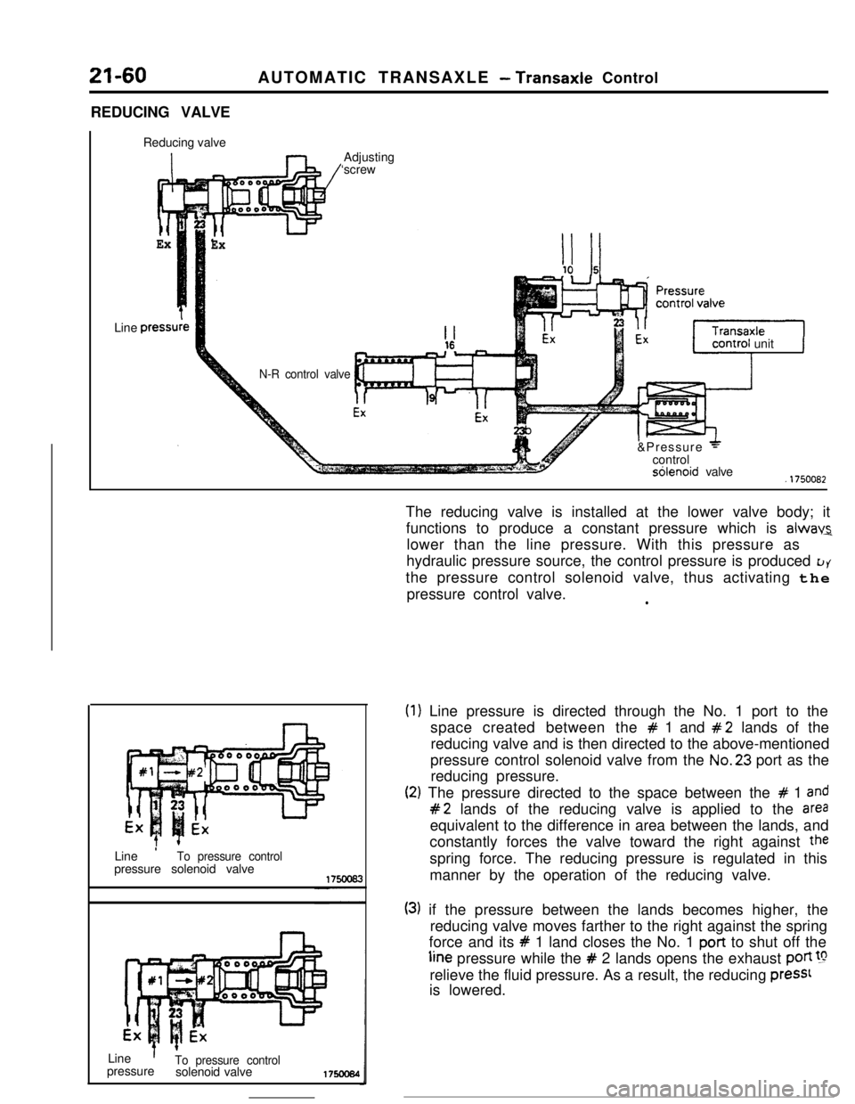
solenoid valve175ocs4The reducing valve is installed at the lower valve body; it
functions to produce a constant pressure which is
alwav2lower than the line pressure. With this pressure as
hydraulic pressure source, the control pressure is produced
LJYthe pressure control solenoid valve, thus activating the
pressure control valve.
l
(1
(2
) Line pressure is directed through the No. 1 port to the
space created between the
# 1 and #2 lands of the
reducing valve and is then directed to the above-mentioned
pressure control solenoid valve from the No.23 port as the
reducing pressure.
:) The pressure directed to the space between the # 1 and
#2 lands of the reducing valve is applied to the areaequivalent to the difference in area between the lands, and
constantly forces the valve toward the right against
thespring force. The reducing pressure is regulated in this
manner by the operation of the reducing valve.
(3) if the pressure between the lands becomes higher, the
reducing valve moves farther to the right against the spring
force and its
# 1 land closes the No. 1 port to shut off theline pressure while the
# 2 lands opens the exhaust poti !grelieve the fluid pressure. As a result, the reducing
press1is lowered.
Page 285 of 391
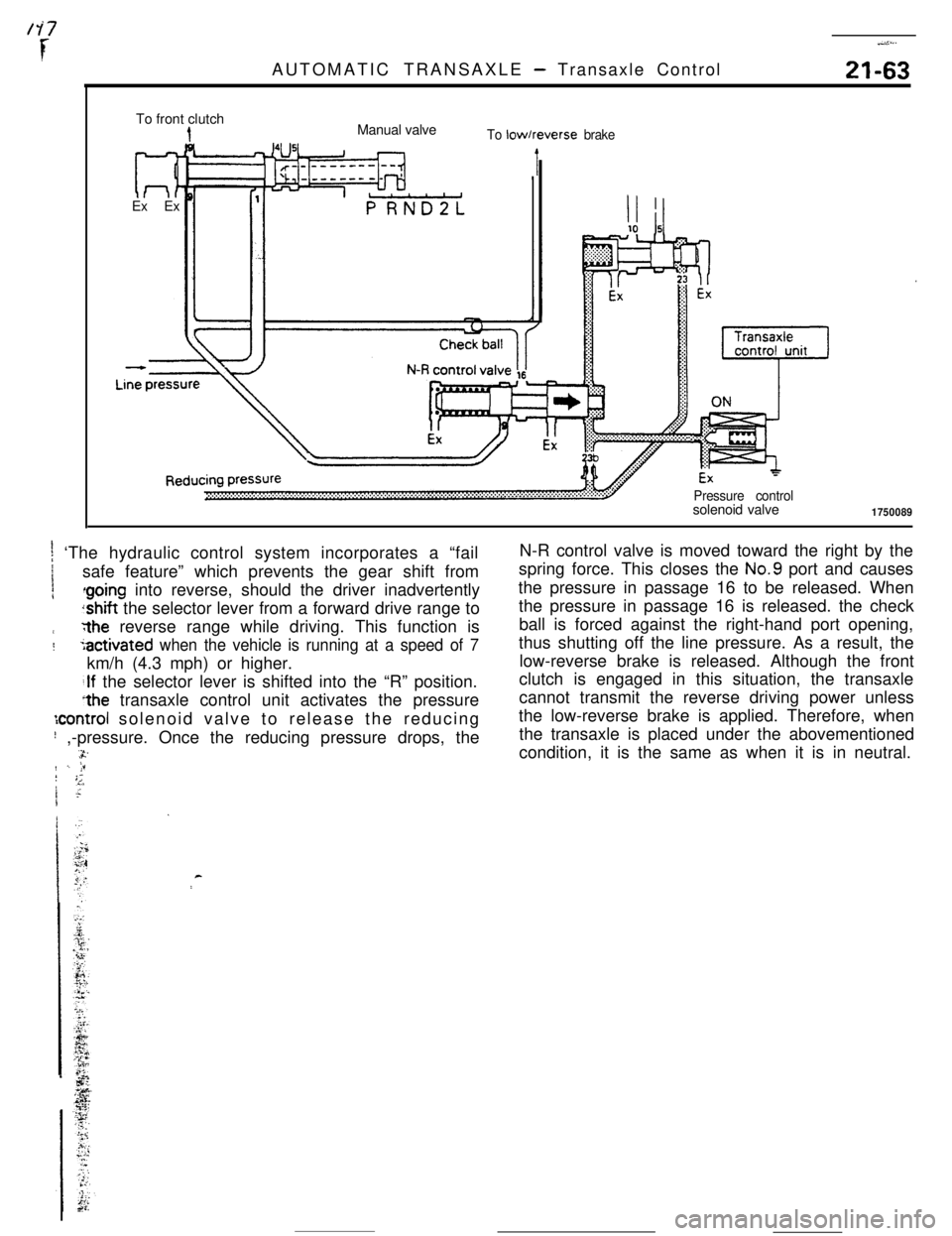
AUTOMATIC TRANSAXLE - Transaxle Control
.-i:...
21-63To front clutch
Ex ExManual valve
To low/reverse brake
Pressure controlsolenoid valve
1750089
t ‘The hydraulic control system incorporates a “fail1
1safe feature” which prevents the gear shift from
irthe reverse range while driving. This function is
:5activated when the vehicle is running at a speed of 7km/h (4.3 mph) or higher.
;If the selector lever is shifted into the “R” position.
*the transaxle control unit activates the pressure
:control solenoid valve to release the reducing
! ,-pressure. Once the reducing pressure drops, the.-a.rr./ -. jF! ;;1 ;I~N-R control valve is moved toward the right by the
spring force. This closes the No.9 port and causes
the pressure in passage 16 to be released. When
the pressure in passage 16 is released. the check
ball is forced against the right-hand port opening,
thus shutting off the line pressure. As a result, the
low-reverse brake is released. Although the front
clutch is engaged in this situation, the transaxle
cannot transmit the reverse driving power unless
the low-reverse brake is applied. Therefore, when
the transaxle is placed under the abovementioned
condition, it is the same as when it is in neutral.
c
Page 286 of 391
-21-64AUTOMATIC TRANSAXLE
- Transaxle Control
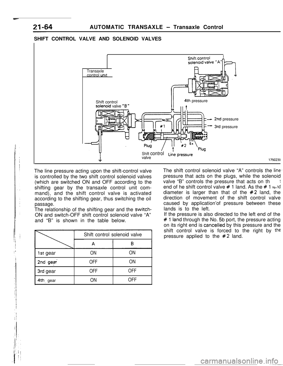
SHIFT CONTROL VALVE AND SOLENOID VALVES
I
ITransaxlecontrol unit
Shift controlsolenoid valve “B
*I4th pressure
Shift controlvalveLine pressure
2nd pressure
3rd pressure
1750230The line pressure acting upon the shift-control valve
is controlled by the two shift control solenoid valves
(which are switched ON and OFF according to the
shifting gear by the transaxle control unit com-
mand), and the shift control valve is activated
according to the shifting gear, thus switching the oil
passage.The relationship of the shifting gear and the switch-
ON and switch-OFF shift control solenoid valve “A”
and “B” is shown in the table below.
Shift control solenoid valve
1st gearONON
2nd geeOFFON
3rd gearOFFOFF
4th. gearONOFFThe shift control solenoid valve “A” controls the
line,pressure that acts on the plugs, while the solenoid
valve “B” controls the pressure that acts on th
tend of he shift control valve
# 1 land. As the # 1 rorlddiameter is larger than that of the
#2 land, the
direction of movement of the shift control valve
caused by application’of pressure between these
lands is to the left.
If the pressure is also directed to the left end of the
# 1 tand through the No. 5b port, the pressure acting
on its right end is
cancelled by this pressure and the
shift control valve is forced to the right by
thepressure applied to the
#2 land.
Page 287 of 391
AUTOMATIC TRANSAXLE - Transaxle Control21-65Shift contra
solenoid val
Shift control valve
To N-Dcontrol valve
To rearclutch
t
Line pressure
-1750231
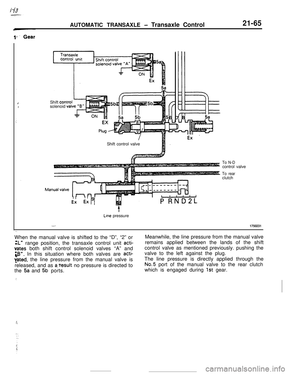
s.When the manual valve is shifted to the “D”, “2” or
GL” range position, the transaxle control unit acti-
Yates both shift control solenoid valves “A” and
3”. In this situation where both valves are acti-
pted, the line pressure from the manual valve is
released, and as
a,Tesult no pressure is directed to
the
5a and 5b ports.
.IMeanwhile, the line pressure from the manual valve
remains applied between the lands of the shift
control valve as mentioned previously. pushing the
valve to the left against the plug.
The line pressure is directly applied through theNo.5 port of the manual valve to the rear clutch
which is engaged during
1st gear.
1::
Page 288 of 391
/
1. .)
21-66
2nd GearAUTOMATIC TRANSAXLE
- Transaxie Control
Plug ’
- 2nd pressure‘:“,,tol, 2 shift
Stopper
To N-Dcontrol valve
To rearclutch -.
Line pressure
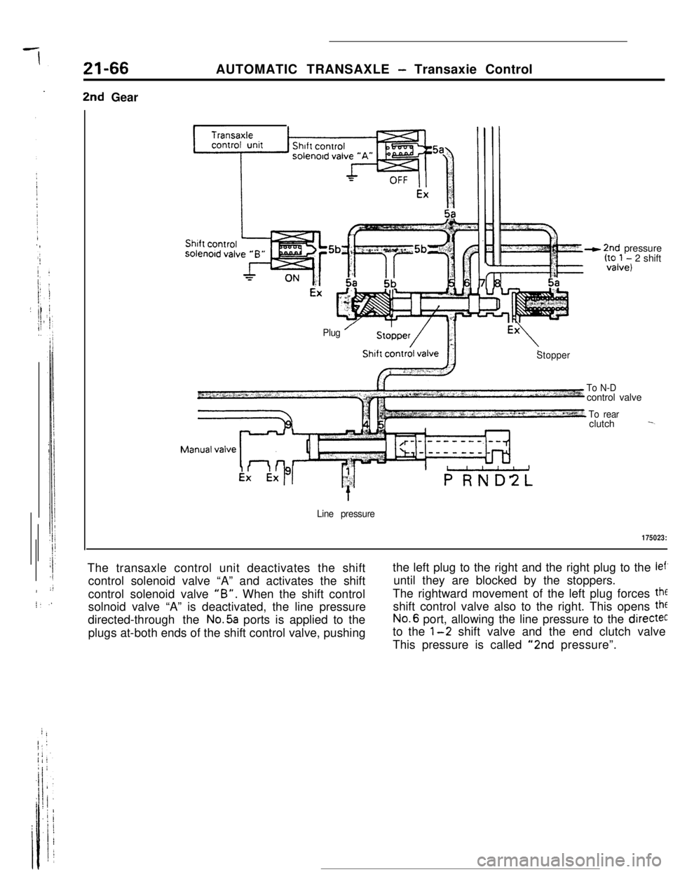
175023:The transaxle control unit deactivates the shift
control solenoid valve “A” and activates the shift
control solenoid valve
“B”. When the shift control
solnoid valve “A” is deactivated, the line pressure
directed-through the
No.5a ports is applied to the
plugs at-both ends of the shift control valve, pushingthe left plug to the right and the right plug to the
lef’until they are blocked by the stoppers.
The rightward movement of the left plug forces
theshift control valve also to the right. This opens
theNo.6 port, allowing the line pressure to the
directecto the
l-2 shift valve and the end clutch valve
This pressure is called
“2nd pressure”.
Page 289 of 391
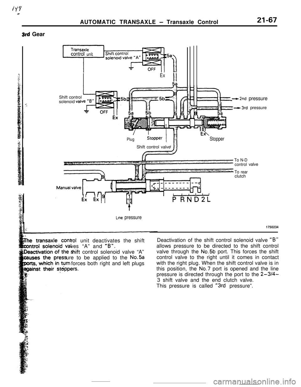
3rd GearAUTOMATIC TRANSAXLE
- Transaxle Control21-67
control unitShift control
solenoid
vail
ExII5a
PlugShift control valve
‘F$&‘- - 2nd pressure
wkh- 3rd pressure
Stopper
Line pressure
rolunit deactivates the shift
ves“A” and “B”.hift control solenoid valve “A”
ure to be applied to the No.5a
forces both right and left plugs
To N-D
control
To rearclutchvalve
1750234Deactivation of the shift control solenoid valve
“B”allows pressure to be directed to the shift control
valve through the No.5b port. This forces the shift
control valve to the right until it comes in contact
with the right plug. When the shift control valve is in
this position, the No.7 port is opened and the line
pressure is directed through the port to the
2-3/4-3 shift valve and the end clutch valve.
This pressure is called
“3rd pressure”.
Page 290 of 391
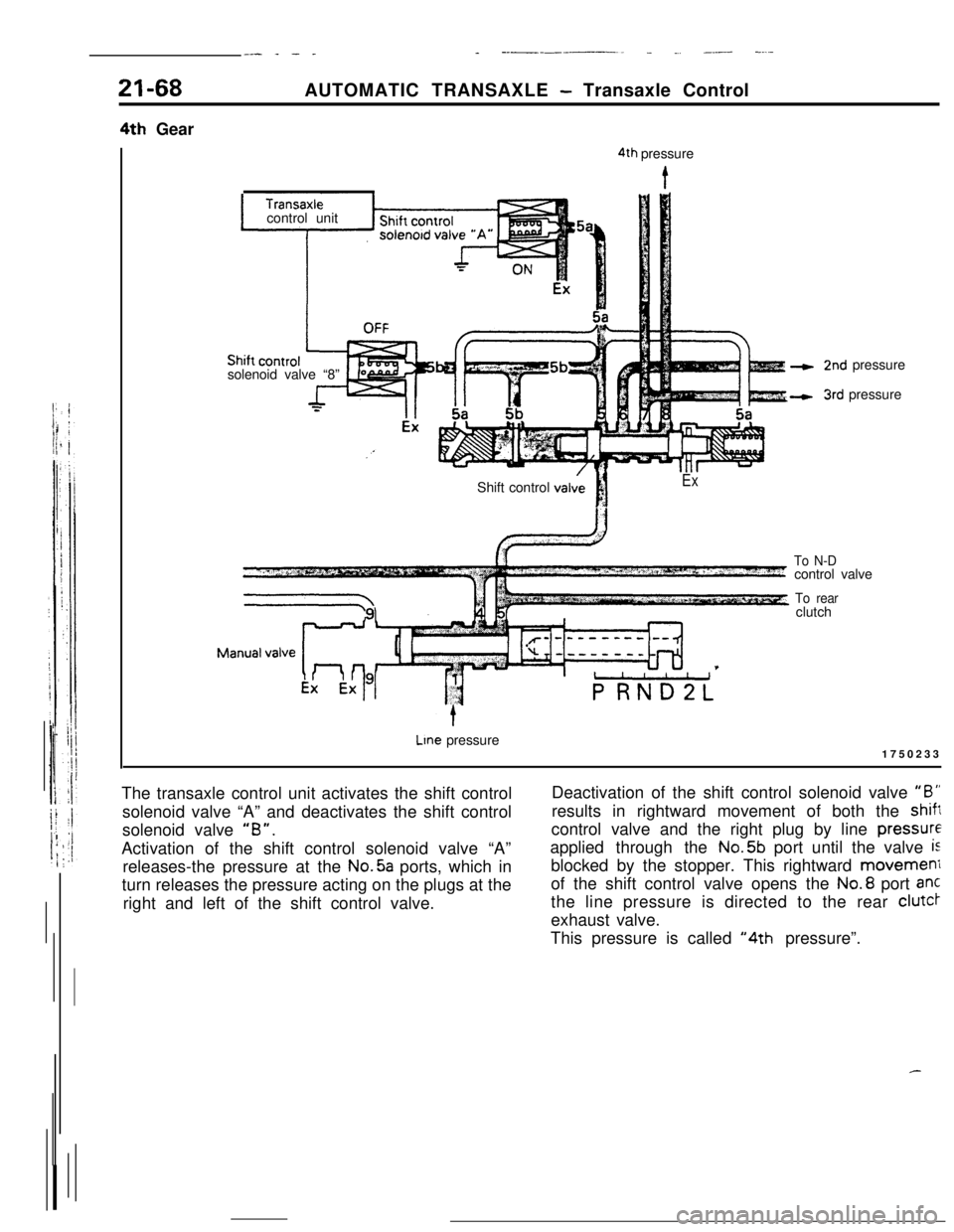
__- _ - __ ----____. _ ., _.- -....21-684th GearAUTOMATIC TRANSAXLE
- Transaxle Control
solenoid valve “8”
4th pressure
Icontrol unit
2nd pressure
3rd pressure
Shift control
valviI!
iEx
To N-Dcontrol valve
To rearclutch
Lme pressure
1750233
The transaxle control unit activates the shift control
solenoid valve “A” and deactivates the shift control
solenoid valve
“B”.Activation of the shift control solenoid valve “A”
releases-the pressure at the No.5a ports, which in
turn releases the pressure acting on the plugs at the
right and left of the shift control valve.Deactivation of the shift control solenoid valve
“B”results in rightward movement of both the
shiftcontrol valve and the right plug by line
pressureapplied through the No.5b port until the valve
isblocked by the stopper. This rightward movemeni
of the shift control valve opens the No.8 port ant
the line pressure is directed to the rear clutcr
exhaust valve.
This pressure is called
“4th pressure”.