MITSUBISHI ECLIPSE 1990 Service Manual
Manufacturer: MITSUBISHI, Model Year: 1990, Model line: ECLIPSE, Model: MITSUBISHI ECLIPSE 1990Pages: 391, PDF Size: 15.27 MB
Page 291 of 391
/gi--__ .--.-9
Reducingvalve
To kickdown
servo via 1 - 2
shift valveLine pressureAUTOMATIC TRANSAXLE
- Transaxle Control21-69
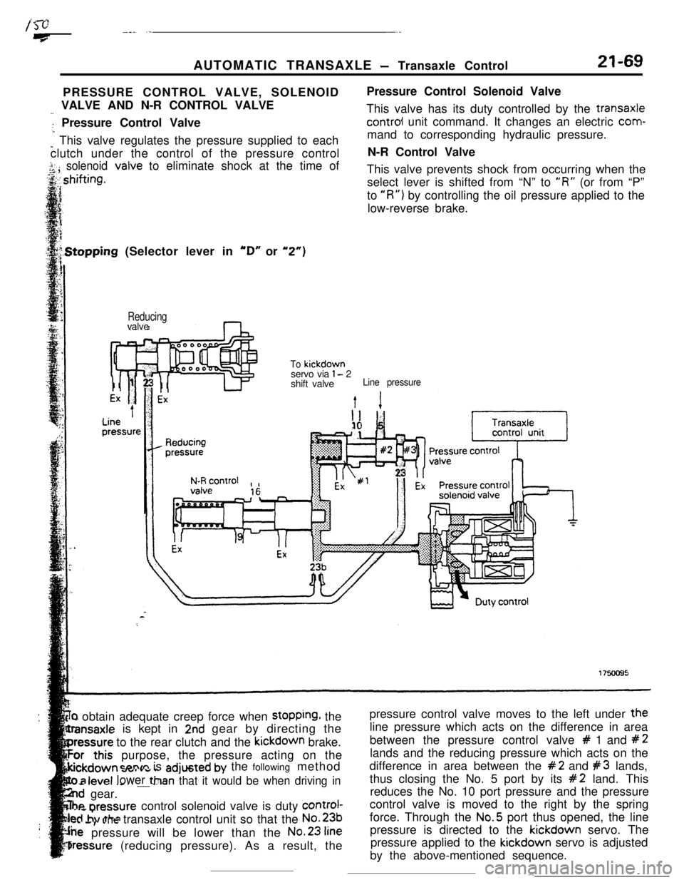
PRESSURE CONTROL VALVE, SOLENOID
-_ VALVE AND N-R CONTROL VALVE
: Pressure Control Valve
: This valve regulates the pressure supplied to each
clutch under the control of the pressure control
j.. solenoid<,A ,valve to eliminate shock at the time ofPressure Control Solenoid Valve
This valve has its duty controlled by the transaxlecontrol unit command. It changes an electric com-
mand to corresponding hydraulic pressure.
N-R Control Valve
This valve prevents shock from occurring when the
select lever is shifted from “N” to
“R” (or from “P”
to
“R”) by controlling the oil pressure applied to the
low-reverse brake..Stopping (Selector lever in
“D” or “2”)
‘r) obtain adequate creep force when stopping, the
is kept in
2nd gear by directing the
to the rear clutch and the kickdown brake.
purpose, the pressure acting on the
=nnm is adjusted by the following method
- .--v.._ _ _ __ --Tan that it would be when driving in
..d gear.
he nrennurecontrol solenoid valve is duty control-
..s,. ..Jtransaxle control unit so that the No.231..a
pressure will be lower than the No.23
fine
bressure (reducing pressure). As a result, the
level lower ttlpressure control valve moves to the left under the
line pressure which acts on the difference in area
between the pressure control valve
# 1 and #2lands and the reducing pressure which acts on the
difference in area between the
#2 and #3 lands,
thus closing the No. 5 port by its
#2 land. This
reduces the No. 10 port pressure and the pressure
control valve is moved to the right by the spring
force. Through the No.5 port thus opened, the line
pressure is directed to the kickdown servo. The
pressure applied to the kickdown servo is adjusted
by the above-mentioned sequence.
-
Page 292 of 391
. : j21-70AUTOMATIC TRANSAXLE
- Transaxle Control1st Gear (Selector Lever in “D” or
“2”)
Reducingvalve
D
1
Ex
4Line
’pressureTo low/reverse
brake via 1 - 2shift valveLine pressure
Ext 1
Reducing0 pressure
1 1 ExPressure control 1 b--,N-R control, ,
\ON (Chty 100%)
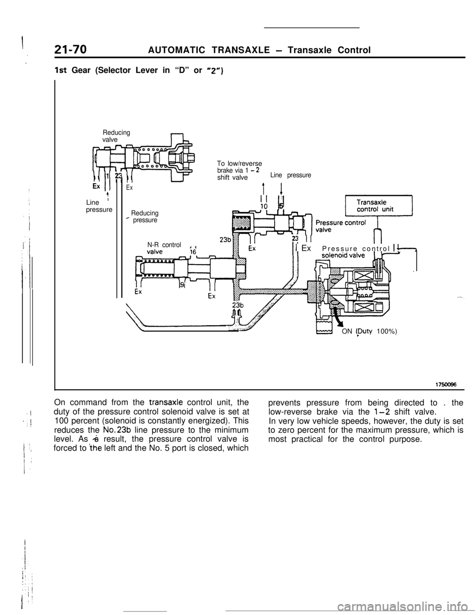
17soo96On command from the
transaxle control unit, the
duty of the pressure control solenoid valve is set at
100 percent (solenoid is constantly energized). This
reduces the No.23b line pressure to the minimum
level. As
4 result, the pressure control valve is
forced to
ihe left and the No. 5 port is closed, whichprevents pressure from being directed to . the
low-reverse brake via the
l-2 shift valve.
In very low vehicle speeds, however, the duty is set
to zero percent for the maximum pressure, which is
most practical for the control purpose.
Page 293 of 391
AUTOMATIC TRANSAXLE - Transaxle Control21-71
‘ift (Selector Lever in “D” or “2”)
ReducingLine
ipressureTo kickdown servo
or from clutch
via3H
l-r
I
1 - 2 shift valve
Line pressure
Ext 1II ”i1
Reducingpressure
N-R control,,
II& Pressure control
solenoid valve
b-l
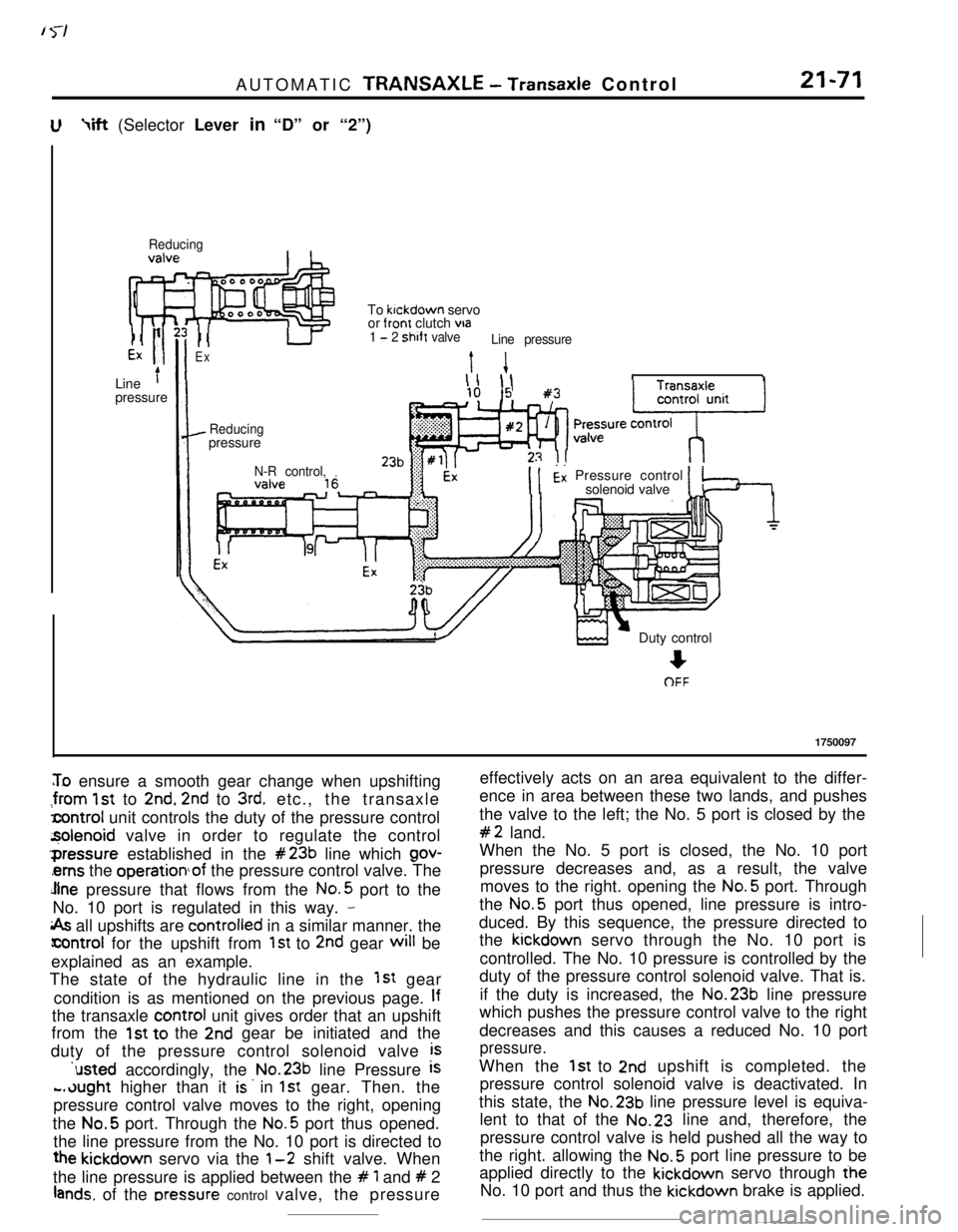
To ensure a smooth gear change when upshifting
:from 1st to 2nd, 2nd to 3rd. etc., the transaxle
lcontrol unit controls the duty of the pressure control
z$olenoid valve in order to regulate the control‘pressure established in the
#23b line which gov-
‘ems the operationof the pressure control valve. The
Jlne pressure that flows from the No.5 port to the
No. 10 port is regulated in this way.
-
i& all upshifts are controlied in a similar manner. the
icontrol for the upshift from 1st to 2nd gear will be
explained as an example.
The state of the hydraulic line in the
1st gear
condition is as mentioned on the previous page.
Ifthe transaxle control unit gives order that an upshift
from the
1st to the 2nd gear be initiated and the
duty of the pressure control solenoid valve
is‘usted accordingly, the No.23b line Pressure
is
-.dught higher than it is. in 1st gear. Then. the
pressure control valve moves to the right, opening
the No.5 port. Through the
No.5 port thus opened.
the line pressure from the No. 10 port is directed to
the kickdown servo via the l-2 shift valve. When
the line pressure is applied between the
# 1 and # 2
lands. of the rxessure control valve, the pressureDuty control
+OFF
1750097
effectively acts on an area equivalent to the differ-
ence in area between these two lands, and pushes
the valve to the left; the No. 5 port is closed by the
#2 land.
When the No. 5 port is closed, the No. 10 port
pressure decreases and, as a result, the valve
moves to the right. opening the No.5 port. Through
the No.5 port thus opened, line pressure is intro-
duced. By this sequence, the pressure directed to
the kickdown servo through the No. 10 port is
controlled. The No. 10 pressure is controlled by the
duty of the pressure control solenoid valve. That is.
if the duty is increased, the No.23b line pressure
which pushes the pressure control valve to the right
decreases and this causes a reduced No. 10 port
pressure.When the
1st to 2nd upshift is completed. the
pressure control solenoid valve is deactivated. In
this state, the No.23b line pressure level is equiva-
lent to that of the No.23 line and, therefore, the
pressure control valve is held pushed all the way to
the right. allowing the No.5 port line pressure to be
applied directly to the kickdown servo through the
No. 10 port and thus the kickdown brake is applied.
Page 294 of 391
21-72AUTOMATIC TRANSAXLE - Transaxle Control
_. --.
1st Gear (Selector Lever in “L”)
ReducingnLow-reverse brake
via 1
- 2 shift
valveLine pressure
Line
’pressureI1
Reducingpressure
N-R control , ,
vaive
16--.. -
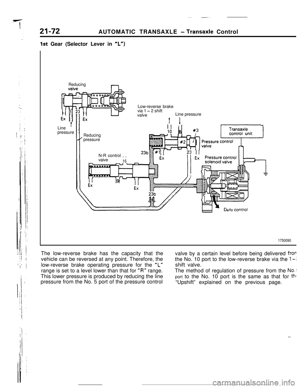
1750090The low-reverse brake has the capacity that the
vehicle can be reversed at any point. Therefore, the
low-reverse brake operating pressure for the
“L”range is set to a level lower than that for
“I?” range.
This lower pressure is produced by reducing the line
pressure from the No. 5 port of the pressure controlvalve by a certain level before being delivered
frorthe No. 10 port to the low-reverse brake via the
1-lshift valve.
The method of regulation of pressure from the
No.:port to the No. 10 port is the same as that for
tht“Upshift” explained on the previous page.
Page 295 of 391
AUTOMATIC TRANSAXLE - Transaxle Control21-73
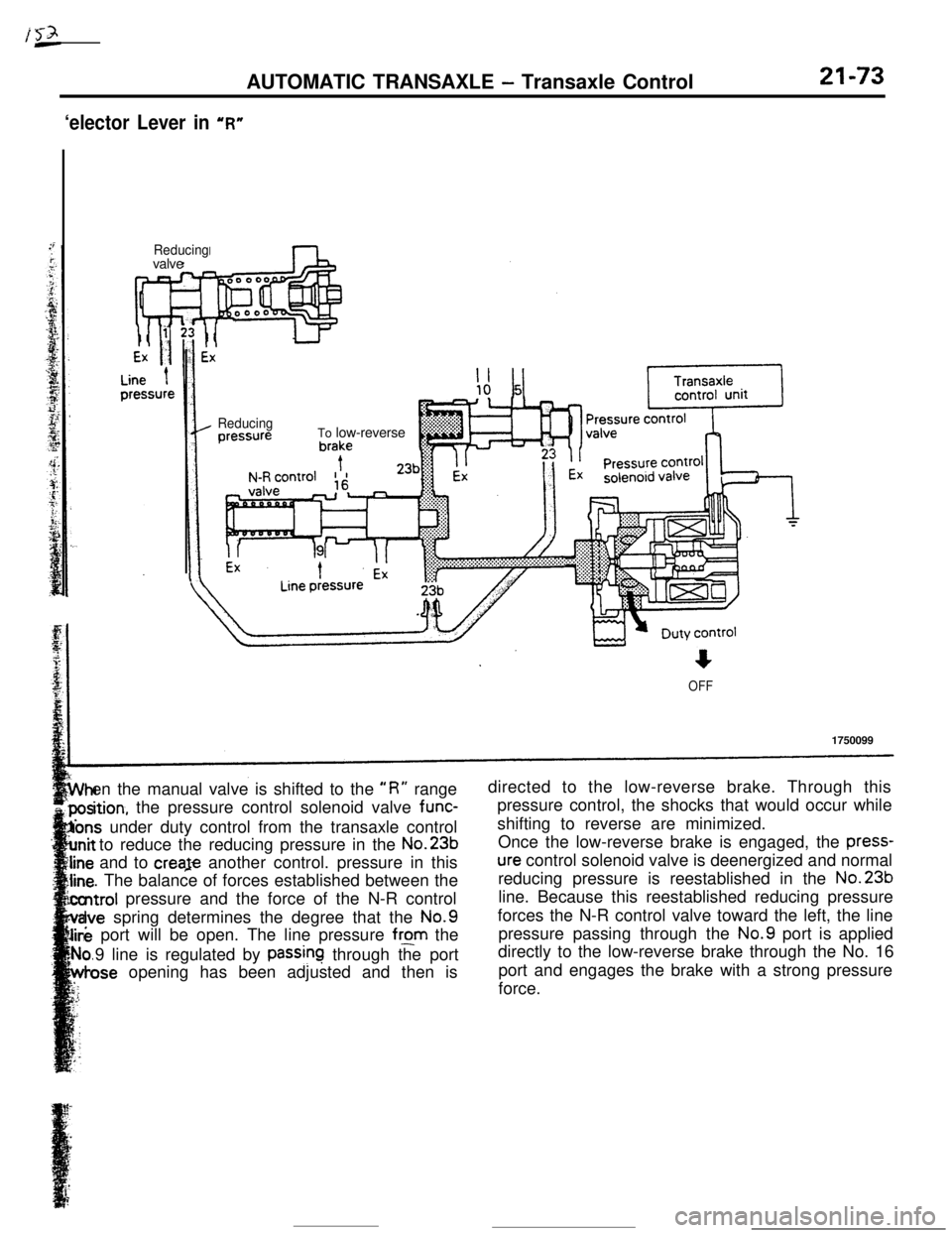
‘elector Lever in “R”
Reducingvalve
ReducingTo low-reverse
OFF1750099
en the manual valve is shifted to the
“R” rangedirected to the low-reverse brake. Through this
ition, the pressure control solenoid valve func-pressure control, the shocks that would occur while
Ions under duty control from the transaxle controlshifting to reverse are minimized.
to reduce the reducing pressure in the No.23bOnce the low-reverse brake is engaged, the press-and to creaje another control. pressure in this
ure control solenoid valve is deenergized and normal
. The balance of forces established between thereducing pressure is reestablished in the No.23bntrol pressure and the force of the N-R controlline. Because this reestablished reducing pressure
Ivespring determines the degree that the No.9forces the N-R control valve toward the left, the line
e port will be open. The line pressure from thepressure passing through the No.9 port is applied
9 line is regulated by
passinq through the portdirectly to the low-reverse brake through the No. 16
ose opening has been adjusted and then isport and engages the brake with a strong pressure
force.
Page 296 of 391
21-74AUTOMATIC TRANSAXLE - Transaxle Control
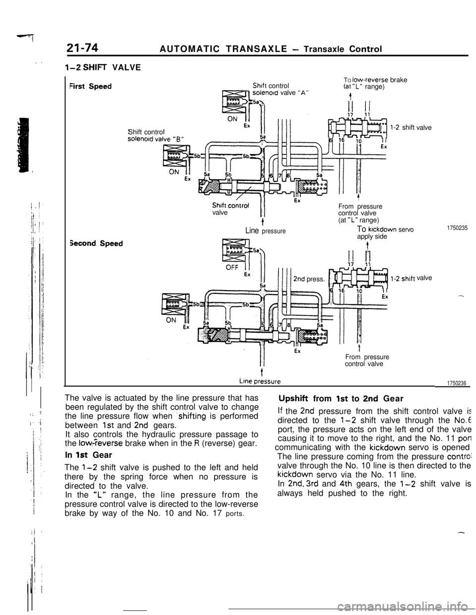
l-2 SHIFT VALVE
First SpeedTO low-reverse brake-Shift control(at “L” range)sorenotd valve “A’.4Shift control
l-2 shift
valve
ON !.IEXShift
coitrol
I/
EX1valve
From pressurecontrol valve
t(at “L” range)
Line pressureTo kickdown servo
l?zza.. -apply sidet
1750235
Second Speed
EX
” IIII2nd press.!iavalve
IFrom pressurecontrol valve
1750236The valve is actuated by the line pressure that has
been regulated by the shift control valve to change
the line pressure flow when .shifting is performed
between
1st and 2nd gears.
It also controls the hydraulic pressure passage to
the
low:-?everse brake when in the R (reverse) gear.
In
1st GearUpsh’ft from
1st to 2nd Gear
If the 2nd pressure from the shift control valve isdirected to the
l-2 shift valve through the No.6port, the pressure acts on the left end of the valve
causing it to move to the right, and the No. 11
poflcommunicating with the kickdown servo is opened
The line pressure coming from the pressure
controivalve through the No. 10 line is then directed to thekickdown servo via the No. 11 line.
In
2nd. 3rd and 4th gears, the 1-2 shift valve is
always held pushed to the right.
) ;‘I
I. 4The
1-2 shift valve is pushed to the left and held
there by the spring force when no pressure is
directed to the valve.
In the
“L” range, the line pressure from the
pressure control valve is directed to the low-reverse
brake by way of the No. 10 and No. 17 ports.
,i
Page 297 of 391
AUTOMATIC TRANSAXLE - Transaxle Control21-75
From kickdown
servo apply side
1Shift control
valve
1-2 shift
1750237
11To low-reverse To low-reversebrake brake
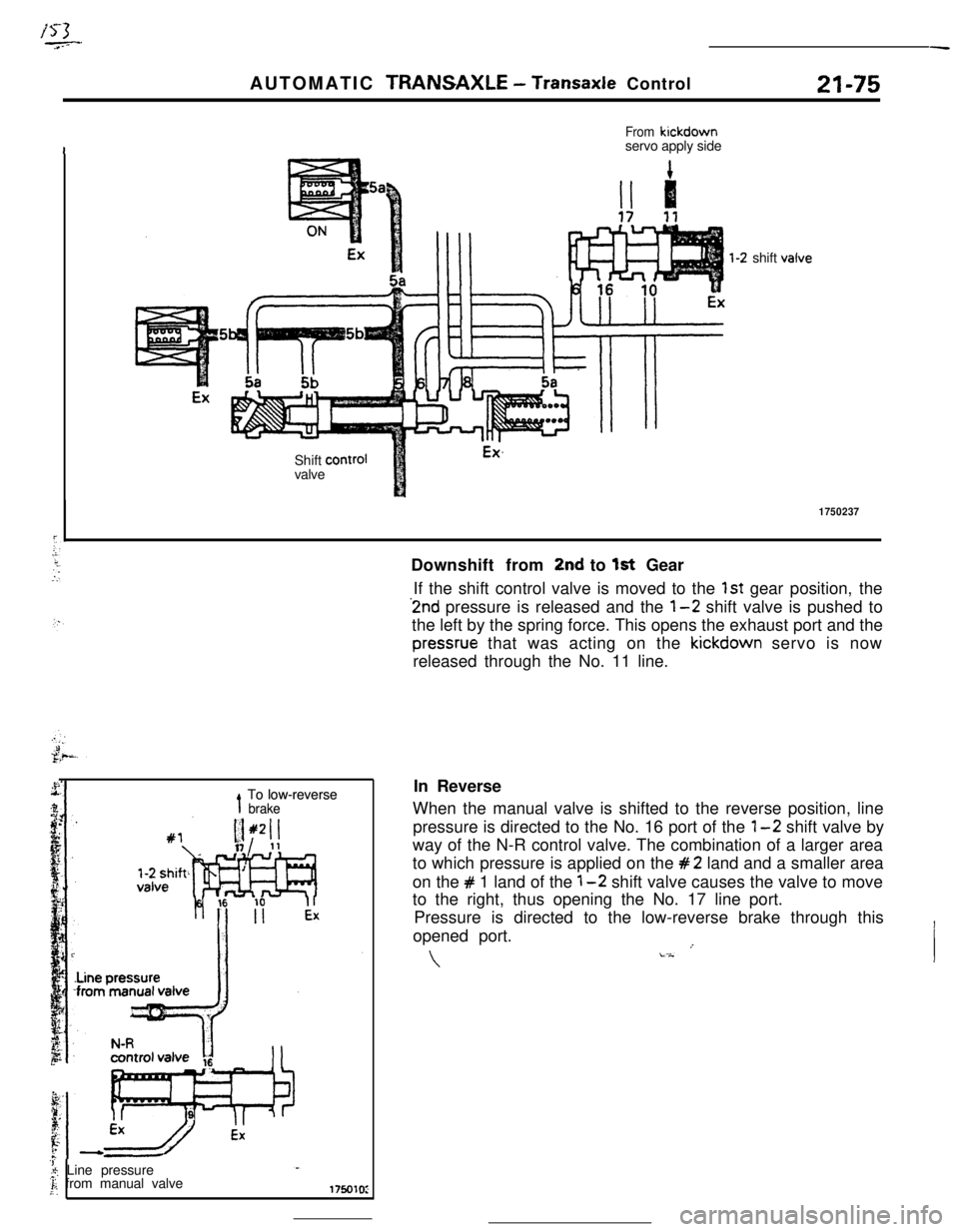
‘1..‘; Line pressure.F: from manual valveDownshift from
2nd to 1st Gear
If the shift control valve is moved to the
1st gear position, the2nd pressure is released and the
l-2 shift valve is pushed to
the left by the spring force. This opens the exhaust port and the
pressrue that was acting on the kickdown servo is now
released through the No. 11 line.
In Reverse
When the manual valve is shifted to the reverse position, line
pressure is directed to the No. 16 port of the
1-2 shift valve by
way of the N-R control valve. The combination of a larger area
to which pressure is applied on the
#2 land and a smaller area
on the
# 1 land of the 1-2 shift valve causes the valve to move
to the right, thus opening the No. 17 line port.
Pressure is directed to the low-reverse brake through this
opened port.
-
Page 298 of 391
?
I
21-76AUTOMATIC TRANSAXLE - Transaxle Control
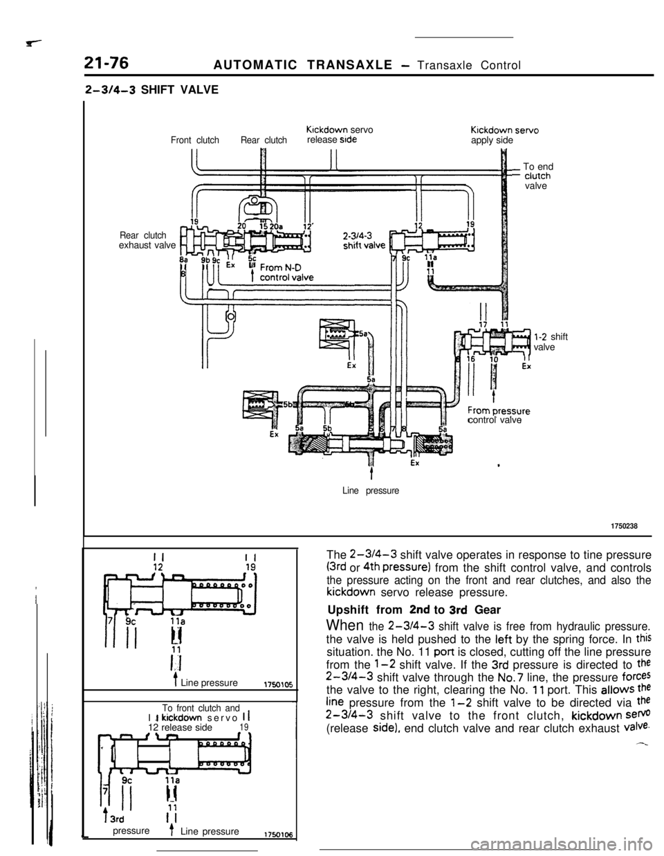
2-314-3 SHIFT VALVE
Rear clutchexhaust valve
Front clutchRear clutchKlckdown servo
release stdeKickdown servo
apply side
?I
l-2 shift
valve
control valve
_ To end- ciutch
valvet
Line pressure
1750238
II
i Line pressure1750105
To front clutch andI 1 kickdown servo 1 112 release side19n fln
IIT3rd
pressure
t- Line pressureThe
2-WI-3 shift valve operates in response to tine pressure
(3rd or 4th pressure) from the shift control valve, and controls
the pressure acting on the front and rear clutches, and also thekickdown servo release pressure.
Upshift from
2nd to 3rd Gear
When the 2-3/4-3 shift valve is free from hydraulic pressure.the valve is held pushed to the left by the spring force. In
thissituation. the No. 11 pan is closed, cutting off the line pressure
from the
1-2 shift valve. If the 3rd pressure is directed to the
2-3/4-3 shift valve through the No.7 line, the pressure forcesthe valve to the right, clearing the No.
11 port. This allows the
fine pressure from the l-2 shift valve to be directed via the
2-3/4-3 shift valve to the front clutch, kickdown sem(release
side), end clutch valve and rear clutch exhaust valve.
Page 299 of 391
![MITSUBISHI ECLIPSE 1990 Service Manual ir yAUTOMATIC TRANSAXLE
- Trahsaxle Control21-774th Gear
3rd GearRear clutchKickdown
1servo
release sideFront clutch
-
Rear clutch3rd1-2 shiftKickdown
Front clutch
q]b Ture,‘r z&eside
7
1750107
1F MITSUBISHI ECLIPSE 1990 Service Manual ir yAUTOMATIC TRANSAXLE
- Trahsaxle Control21-774th Gear
3rd GearRear clutchKickdown
1servo
release sideFront clutch
-
Rear clutch3rd1-2 shiftKickdown
Front clutch
q]b Ture,‘r z&eside
7
1750107
1F](/img/19/57103/w960_57103-298.png)
ir yAUTOMATIC TRANSAXLE
- Trahsaxle Control21-774th Gear
3rd GearRear clutchKickdown
1servo
release sideFront clutch
-
Rear clutch3rd1-2 shiftKickdown
Front clutch
q]b Ture,‘r z&eside
7
1750107
1Fromk-D3rd 14th pressure
control valve1 ;l;hiftpressure1750108
Upshift from
3rd to 4th Gear
.When the 4th pressure (line pressure) from the shift
control valve is directed to the rear clutch exhaust
valve through the No.8 line. the valve is pushed to
the right, closing the No.5c port. This cuts off the
pressure to the rear clutch and also releases the
pressure acting on the rear clutch through NO.
15port, No.20a port and No. 20
port.On the other hand, the rear clutch exhaust
valvewhich is pushed to the right opens the NO. 19
POnand directs the 4th pressure (line pressure) to the
right end of the
2-3/4-3 shift valve. The 3rdpressure (or the No.7 line pressure) is acting on theleft
end of the 2-3/4-3 shift valve. As this Pressure
..is equal to the No. 19 line pressure and acts on the
Mme area, the spring at the right end of the valveWhen the 4th pressure is released by the move-
ment of the shift control valve, the rear clutchDownshift from 4th to
3rd Gear
exhaust valve moves to the left, creating a
3rd gearstate, and the pressure is directed to the rear clutch.
At the same time as this happens, the 4th pressure
in No. 19 line which has been acting on the 2-3/4-3shift valve is released. This causes the
3rd pressure
established in the
No.7 line to push the 2-3/4-3shift valve to the right, and creates a 3rd gear state
where the line pressure from the
l-2 shift valve is
directed to the front clutch and the release side
chamber of kickdown servo cylinder through the
No. 12 line.shes the valve toward the
left. closing the No. 11me pressure port. This
btocks the pressure to the
front clutch and the release side chamber ofkickdown servo cylinder, and the pressure is re-
leased through the No. 12. and then the
No.9~ Pofi.
Page 300 of 391
21-78AUTOMATIC TRANSAXLE - Transaxle Control
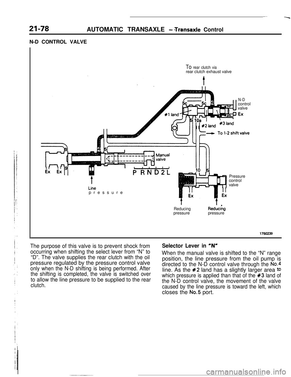
N-D CONTROL VALVE
.-.‘r
To rear clutch viarear clutch exhaust valve
N-Dcontrol
valve
EXpressure
Pressurecontrol
valve
t
Reducingpressure
t
Red”&pressure
175oz39
The purpose of this valve is to prevent shock from
occurring when shifting the select lever from “N” to
“D”. The valve supplies the rear clutch with the oilpressure regulated by the pressure control valve
only when the N-D shifting is being performed. After
the shifting is completed, the valve is switched over
to allow the line pressure to be supplied to the rear
clutch.
Selector Lever in ‘N”
When the manual valve is shifted to the “N” rangeposition, the line pressure from the oil pump is
directed to the N-D control valve through the No.4line. As the
#2 land has a slightly larger area to
which pressure is applied than that of the #3 land of
the N-D control valve, the movement of the valve
caused by the line pressure is toward the left, whichcloses the
No.5 port.