MITSUBISHI ECLIPSE 1990 Service Manual
Manufacturer: MITSUBISHI, Model Year: 1990, Model line: ECLIPSE, Model: MITSUBISHI ECLIPSE 1990Pages: 391, PDF Size: 15.27 MB
Page 261 of 391
AUTOMATIC TRANSAXLE - Transaxle Mechanism21-37
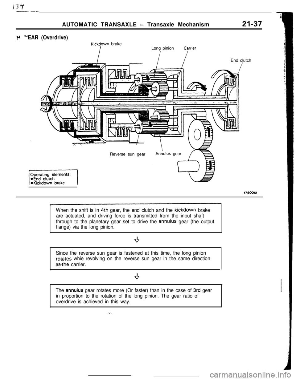
‘EAR (Overdrive)
Kickdown brake
Long pinionCarrterEnd clutch
Reverse sun gear
AnLlus gear
175006l
When the shift is in 4th gear, the end clutch and the kickdown brake
are actuated, and driving force is transmitted from the input shaft
through to the planetary gear set to drive the
annulus gear (the output
flange) via the long pinion.
1
Since the reverse sun gear is fastened at this time, the long pinioniotates
whie revolving on the reverse sun gear in the same directiona?ihe
carrier.
The
annulus gear rotates more (Or faster) than in the case of 3rd gear
in proportion to the rotation of the long pinion. The gear ratio of
overdrive is achieved in this way.
Page 262 of 391
21-38RNERSEAUTOMATIC TRANSAXLE - Transaxle Mechanism
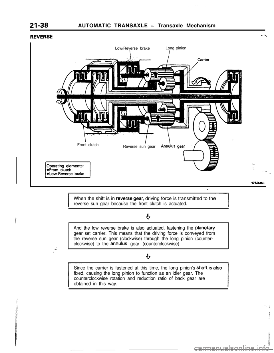
Low/Reverse brakeLong pinion
\I
IFront clutchIReverse sun gearIAnnulus
l
IWhen the shift is in
reverse.gear, driving force is transmitted to the
reverse sun gear because the front clutch is actuated.-1
And the low reverse brake is also actuated, fastening the planetan/
gear set carrier. This means that the driving force is conveyed from
the reverse sun gear (clockwise) through the long pinion (counter-
clockwise) to the
annulus gear (counterclockwise).*
/
- ~~_~
Since the carrier is fastened at this time, the long pinion’s
fixed, causing the long pinion to function as an idler gear. The
counterclockwise rotation and reduction ratio of back gear are
obtained in this way.
Page 263 of 391
AUTOMATIC TRANSAXLE - Transaxle Mechanism
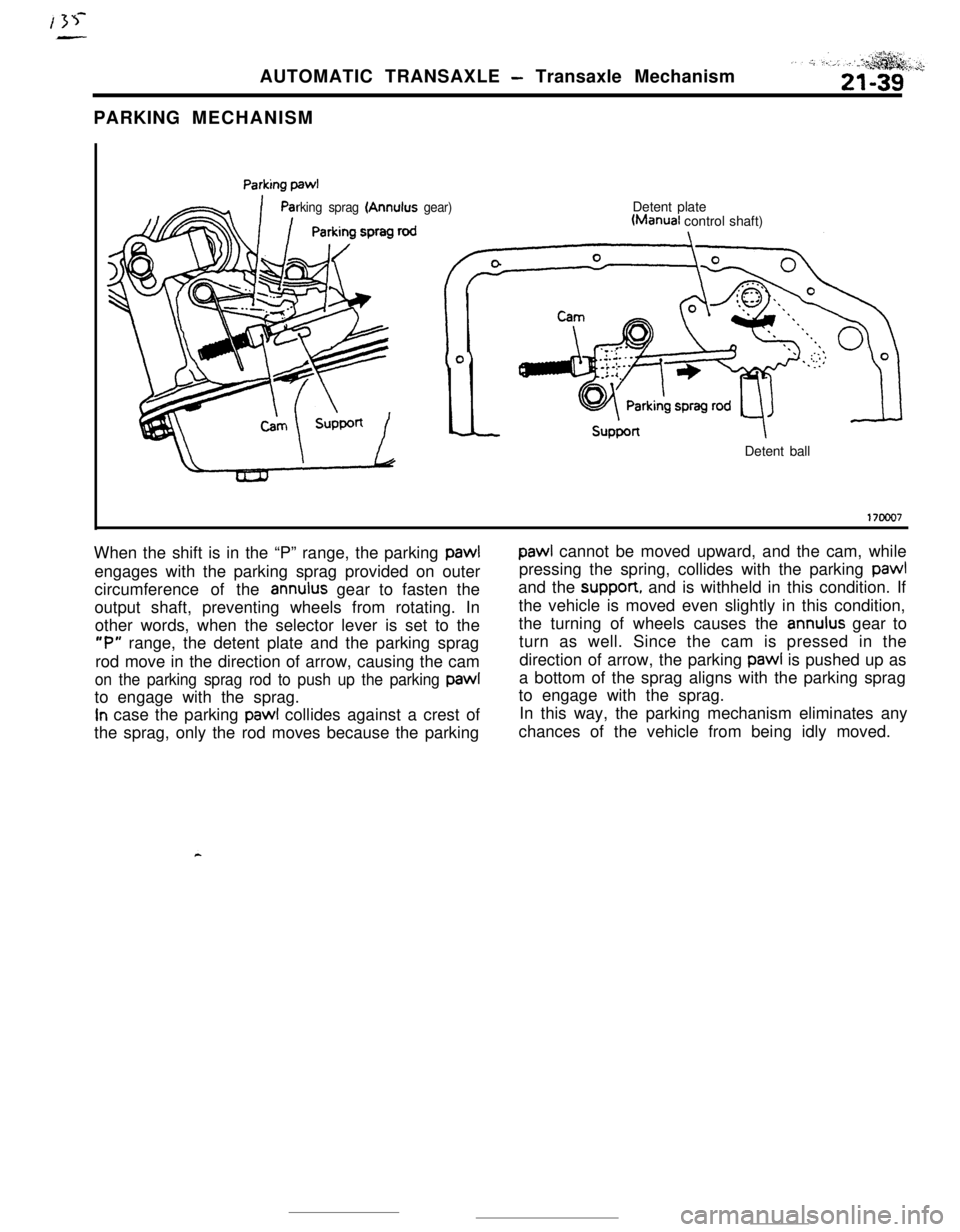
PARKING MECHANISM
rking sprag (Annulus gear)Detent plateWanual control shaft)
Detent ball
17ooo7When the shift is in the “P” range, the parking pawl
paw1 cannot be moved upward, and the cam, while
engages with the parking sprag provided on outerpressing the spring, collides with the parking
paw1circumference of the
annulus gear to fasten theand the suppon, and is withheld in this condition. If
output shaft, preventing wheels from rotating. Inthe vehicle is moved even slightly in this condition,
other words, when the selector lever is set to thethe turning of wheels causes the
annulus gear to
“P” range, the detent plate and the parking spragturn as well. Since the cam is pressed in the
rod move in the direction of arrow, causing the camdirection of arrow, the parking pawl is pushed up as
on the parking sprag rod to push up the parking paw1a bottom of the sprag aligns with the parking sprag
to engage with the sprag.to engage with the sprag.
In case the parking paw1 collides against a crest of
the sprag, only the rod moves because the parkingIn this way, the parking mechanism eliminates any
chances of the vehicle from being idly moved.
Page 264 of 391
21-40AUTOMATIC TRANSAXLE - Transaxle Mechanism
START SAFETY MECHANISM
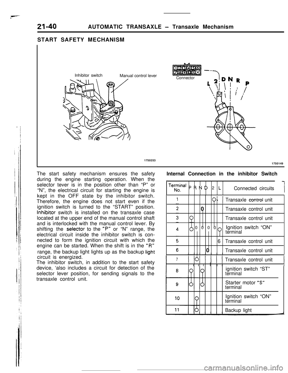
Inhibitor switch
Manual control lever
--
Connector-7DN R
‘,T,i \ ! I
‘\FlI
\ L
,p
( /1750253
1750149
Internal Connection in the inhibitor Switch
,
Teh;ina’ P R N D 2 LConnected circuits1 The start safety mechanism ensures the safety
during the engine starting operation. When the
selector tever is in the position other than “P” or
“N”, the electrical circuit for starting the engine is
kept in the OFF state by the inhibitor switch.
Therefore, the engine does not start even if the
ignition switch is turned to the “START” position.Inhibitor switch is installed on the transaxle case
located at the upper end of the manual control shaft
and is interlocked with the manual control lever. By
shifting the selector to the
“P” or “N” range, the
electrical circuit inside the inhibitor switch is con-
nected to form the ignition circuit with which the
engine can be started. When the shift is in the
“R”range, the backup light lights up as the backup
lightcircuit is energized.
The inhibitor switch, in addition to the start safety
device, ‘also includes a circuit for detection of the
selector lever position, for sending signals to the
transaxle control unit.
011Transaxle control unit0
Transaxle control unit
Transaxle control unit0000Ignition switch “ON”
terminal6
Transaxle control unit0
Transaxle control unit
I
7) 161 ) 1 ( 1Transaxle control unit
I I I I I I IIignition switch “ST”
terminalStarter motor “S”
terminal
10Ignition switch “ON”terminal
Backup light
Page 265 of 391
AUTOMATIC TRANSAXLE - Transaxle Mechanism21-41
YWNSAXLE CONTROL
GENERAL DESCRIPTION
Hydraulic-pressure
control mechanism
Electronic
control-
r
1Pulse oenerator A
DanI
iI11. . . .
control solenola
valve
Pressure controlsolenoid valve
Shift cOntrOisolenoid valve
r-7i1
Diagnosis
connector
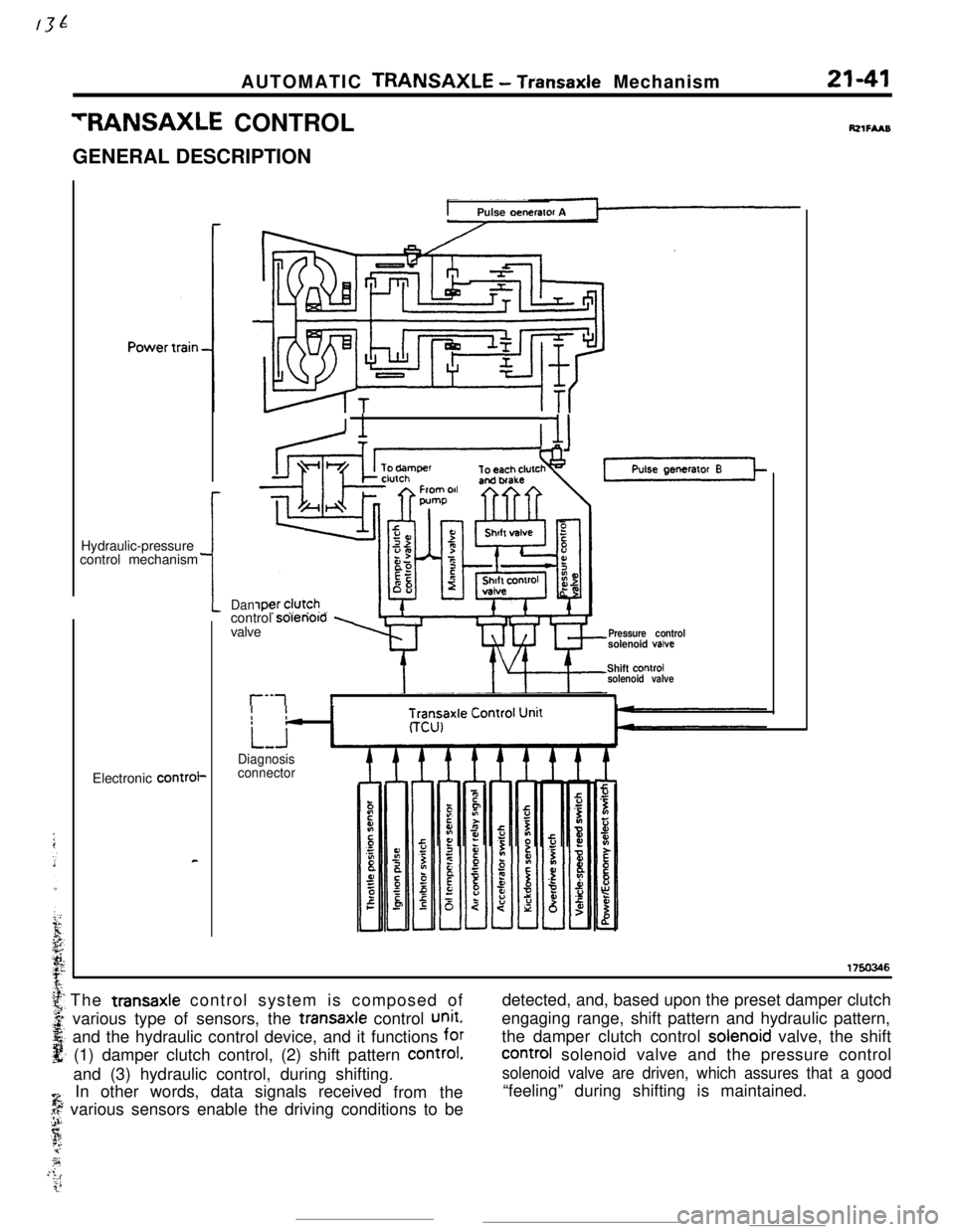
Ft2iFu~The transaxle control system is composed of
various type of sensors, the transaxle control
unit.and the hydraulic control device, and it functions for
(1) damper clutch control, (2) shift pattern
Control.and (3) hydraulic control, during shifting.
%, In other words, data signals received
fromthe
.$ various sensors enable the driving conditions to beJ-
sj.q’74:i.&f’detected, and, based upon the preset damper clutch
engaging range, shift pattern and hydraulic pattern,
the damper clutch control solenoid valve, the shift
Control solenoid valve and the pressure control
solenoid valve are driven, which assures that a good“feeling” during shifting is maintained.
Page 266 of 391
21-42AUTOMATIC TRANSAXLE - Transaxle Control
ELECTRONIC CONTROL DEVICE
DAMPER CLUTCH CONTROL
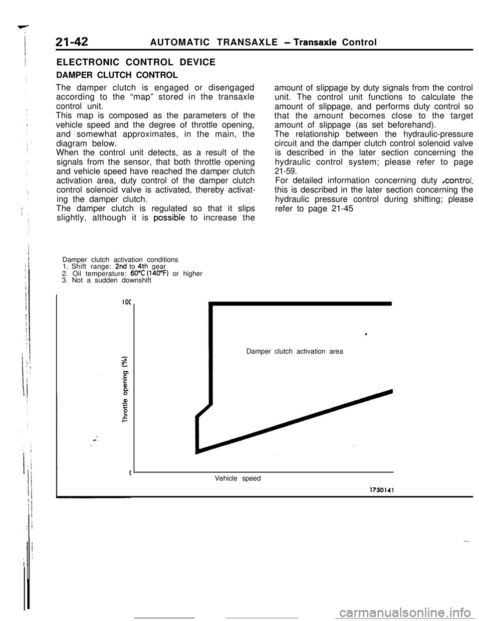
The damper clutch is engaged or disengaged
according to the “map” stored in the transaxle
control unit.
This map is composed as the parameters of the
vehicle speed and the degree of throttle opening,
and somewhat approximates, in the main, the
diagram below.
When the control unit detects, as a result of the
signals from the sensor, that both throttle opening
and vehicle speed have reached the damper clutch
activation area, duty control of the damper clutch
control solenoid valve is activated, thereby activat-
ing the damper clutch.
The damper clutch is regulated so that it slips
slightly, although it is
possible to increase the
Damper clutch activation conditions
1. Shift range:
2nd to 4th gear
2. Oil temperature: 60°C (l4oOF) or higher
3. Not a sudden downshift
IOCamount of slippage by duty signals from the control
unit. The control unit functions to calculate the
amount of slippage, and performs duty control so
that the amount becomes close to the target
amount of slippage (as set beforehand).
The relationship between the hydraulic-pressure
circuit and the damper clutch control solenoid valve
is described in the later section concerning the
hydraulic control system; please refer to page
21-59.For detailed information concerning duty ,control,
this is described in the later section concerning the
hydraulic pressure control during shifting; please
refer to page 21-45,
Damper clutch activation area
Vehicle speed
Page 267 of 391
AUTOMATIC TRANSAXLE - Transaxle Control21-43
“YIR PAllERN CONTROL
,e gear shifting sequence is performed as follows:
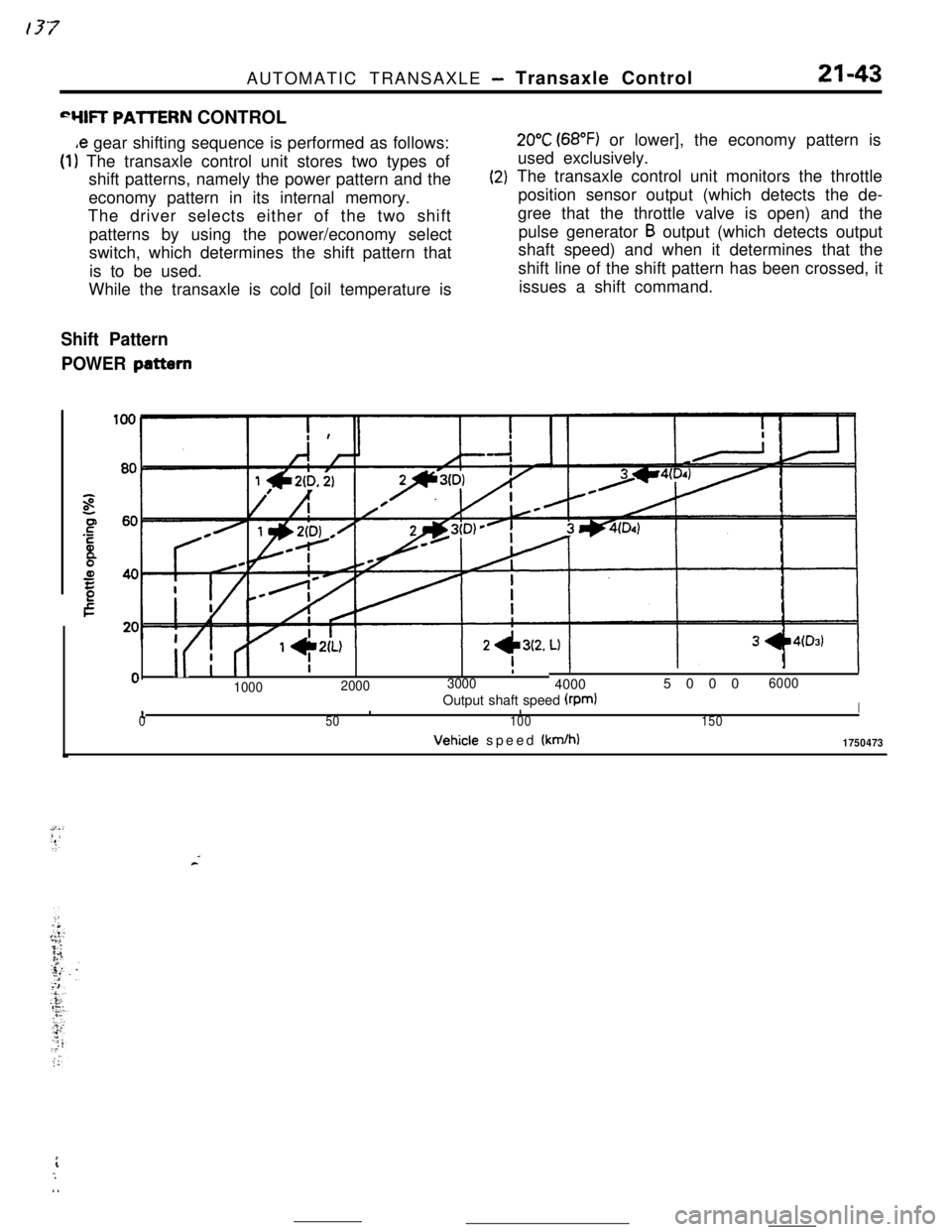
(1) The transaxle control unit stores two types of
shift patterns, namely the power pattern and the
economy pattern in its internal memory.
The driver selects either of the two shift
patterns by using the power/economy select
switch, which determines the shift pattern that
is to be used.
While the transaxle is cold [oil temperature is
(2)
Shift Pattern
POWER
pattern
20°C (68°F) or lower], the economy pattern is
used exclusively.
The transaxle control unit monitors the throttle
position sensor output (which detects the de-
gree that the throttle valve is open) and the
pulse generator
B output (which detects output
shaft speed) and when it determines that the
shift line of the shift pattern has been crossed, it
issues a shift command.
i
II I (I
I -L\LI1- --‘-0
II
0I
100020003000
II400050006000
10Output shaft speed (rpmlIII50100150Vehicle speed
(km/h)1750473
rL;. .
Page 268 of 391
_-..21-44AUTOMATIC TRANSAXLE
- Transaxle Control
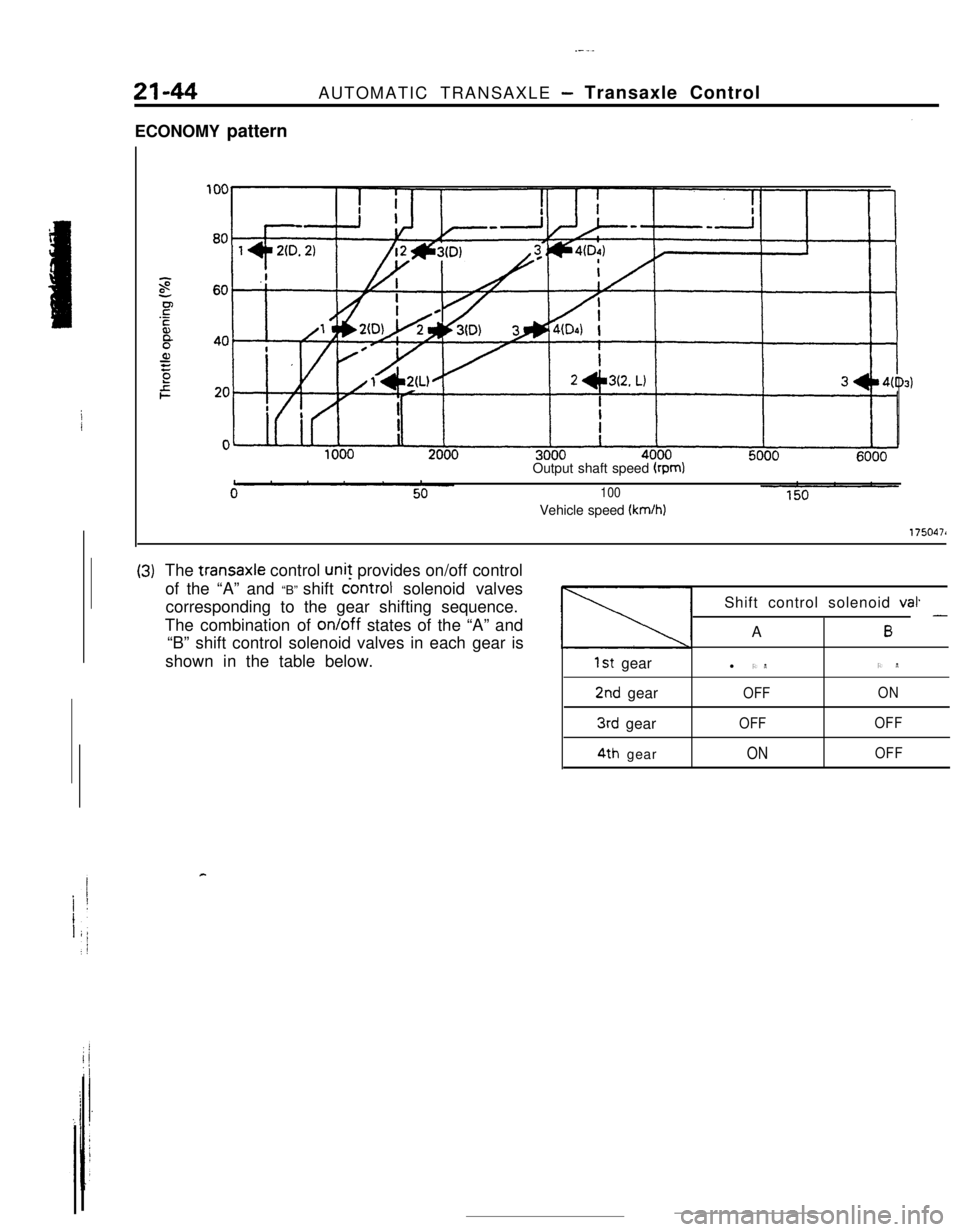
ECONOMY pattern
Output shaft speed
(rpm)
100Vehicle speed
(km/h)
1750471
(3)The transaxle control unit provides on/off control
of the “A” and “B” shift
controt solenoid valves
corresponding to the gear shifting sequence.
The combination of on/off states of the “A” and
“B” shift control solenoid valves in each gear is
shown in the table below.
1st gear
2nd gear
3rd gear
4th gearShift control solenoid
val.A
6 -l ONON
OFFON
OFFOFF
ONOFF
c
Page 269 of 391
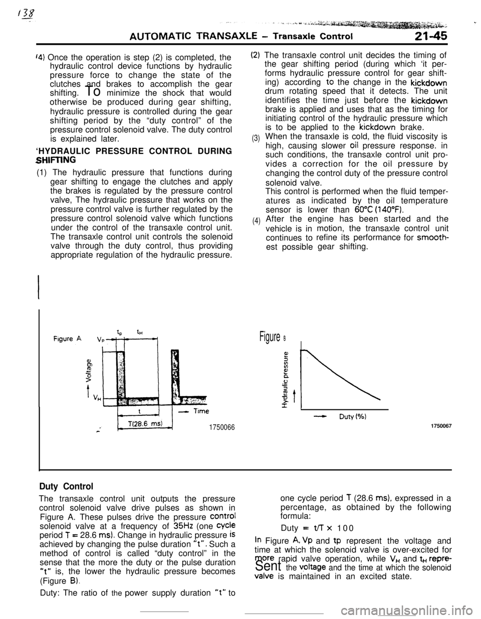
‘4) Once the operation is step (2) is completed, the
hydraulic control device functions by hydraulic
pressure force to change the state of the
clutches and brakes to accomplish the gear
shifting. To minimize the shock that would
otherwise be produced during gear shifting,
hydraulic pressure is controlled during the gear
shifting period by the “duty control” of the
pressure control solenoid valve. The duty control
is explained later.
‘HYDRAULIC PRESSURE CONTROL DURING
SHFIING(1) The hydraulic pressure that functions during
gear shifting to engage the clutches and apply
the brakes is regulated by the pressure control
valve, The hydraulic pressure that works on the
pressure control valve is further regulated by the
pressure control solenoid valve which functions
under the control of the transaxle control unit.
The transaxle control unit controls the solenoid
valve through the duty control, thus providing
appropriate regulation of the hydraulic pressure.
(2)
(3)
(4)The transaxle control unit decides the timing of
the gear shifting period (during which ‘it per-
forms hydraulic pressure control for gear shift-
ing) according to the change in the kickdown
drum rotating speed that it detects. The unit
identifies the time just before the kickdown
brake is applied and uses that as the timing for
initiating control of the hydraulic pressure which
is to be applied to the kickdown brake.
When the transaxle is cold, the fluid viscosity is
high, causing slower oil pressure response. in
such conditions, the transaxle control unit pro-
vides a correction for the oil pressure by
changing the control duty of the pressure control
solenoid valve.
This control is performed when the fluid temper-
atures as indicated by the oil temperature
sensor is lower than
60°C (140°F).After the engine has been started and the
vehicle is inmotion, the transaxle
continues torefine its performance
est possiblegear shifting.control unit
for smooth-
tHFigure B
- Duty(%)
17500661750067
Duty ControlThe transaxle control unit outputs the pressureone cycle period
T (28.6 ms), expressed in a
control solenoid valve drive pulses as shown inpercentage, as obtained by the following
formula:
Figure A. These pulses drive the pressure
COrmIsolenoid valve at a frequency of
35Hz (one Cycleperiod
T = 28.6 ms). Change in hydraulic pressure iSDuty =t/-r x 100
achieved by changing the pulse duration
“t”. Such aIn Figure A, Vp and tp represent the voltage and
method of control is called “duty control” in thetime at which the solenoid valve is over-excited for
sense that the more the duty or the pulse duration
more rapid valve operation, while V,, and t+., repre-
“t” is, the lower the hydraulic pressure becomesSent the v,oltage and the time at which the solenoid(Figure
B).Valve is maintained in an excited state.
Duty: The ratio of the power supply duration
“t” to
Page 270 of 391
---21-46AUTOMATIC TRANSAXLE
- Transaxle Control
Figure A
IICITime (sec.)f
IiFigureB ,
II
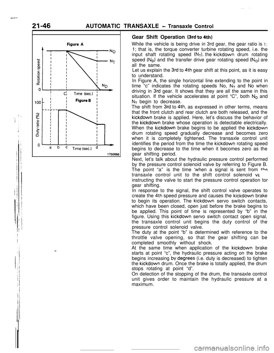
cGear Shift Operation
(3rd to 4th)While the vehicle is being drive in
3rd gear, the gear ratio is I :1; that is, the torque converter turbine rotating speed, i.e. the
input shaft rotating speed
(NT), the kickdown drum rotating
speed
(No) and the transfer drive gear rotating speed (No) are
all the same.
Let us explain the
3rd to 4th gear shift at this point, as it is easy
to understand.
In Figure A, the single horizontal line extending to the point in
time “c” indicates the rotating speeds No,
NT and No when
driving in
3rd gear. It shows that they are all the same in this
situation. If the vehicle accelerates at point “C”, both
No and
NT begin to decrease.
The shift from
3rd to 4th, as expressed in other terms, means
that the front clutch and rear clutch are both released, and thekickdown brake is applied. Here, let’s discuss the behavior of
the kickdown brake whose operation is detectable electrically.
When the kickdown brake begins to be applied the kickdown
drum rotating speed gradually decrease and becomes zero
when it is completely tightened. The transaxle control unit
identifies the period from the time the kickdown rotating speed
begins to decrease to the time when it becomes zero as the
gear shifting period.
Next, let’s talk about the hydraulic pressure control performed
by the pressure control solenoid valve by referring to Figure B.
The point “a”is the time ‘when a signal is sent from tbg
transaxle control unit to the shift control solenoid
viinstructing the valve to start the pressure control operation tor
gear shifting.
In response to the signal, the shift control valve operates to
create the 4th speed pressure and causes the kickdown brake
to begin its operation. The kickdown servo switch contacts,
which have been closed, open just before the brake begins to
be applied. This point of time is represented by “b” in the
figure. Using this kickdown servo switch contact open signal,
the transaxle control unit begins the duty control of the
pressure control solenoid valve.
The duty at the point “b” is determined with reference to the
throttle valve opening, so that the gear shifting can be
completed smoothly without shock.
At the same time when application of the kickdown brake
starts at point “c”, the hydraulic pressure acting on the brake
begins increasing by.degrees (i.e. duty is decreased) to tighten
the kickdown drum. Once the brake is totally applied, the drum
stops rotating at point “d”.
On detection of the stopping of the drum, the transaxle control
unit gives order to maintain the hydraulic pressure at a
maximum.