brake MITSUBISHI ECLIPSE 1990 Owner's Manual
[x] Cancel search | Manufacturer: MITSUBISHI, Model Year: 1990, Model line: ECLIPSE, Model: MITSUBISHI ECLIPSE 1990Pages: 391, PDF Size: 15.27 MB
Page 244 of 391
-_ - .--.7
!21-20AUTOMATIC TRANSAXLE - A/T Safety-lock System
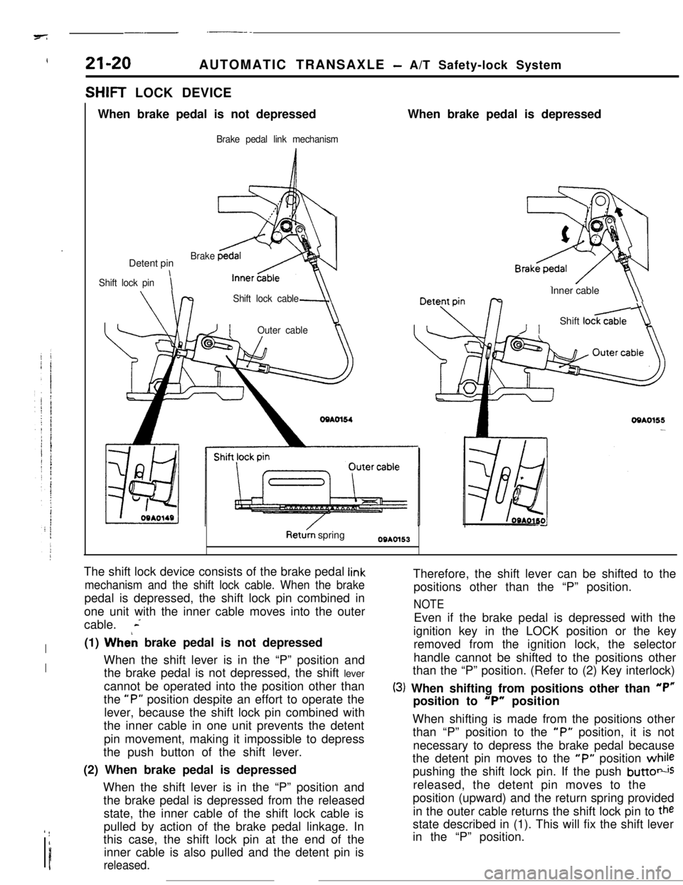
SHIFT LOCK DEVICE
When brake pedal is not depressed
Brake pedal link mechanismWhen brake pedal is depressed
Detent pin
Shift lock pini
Brake
Shift lock cable
-JIOuter cableInner cable
\\
/IShift loc&
OQAO155-
Ret& springOBAOl53
The shift lock device consists of the brake pedal
link
mechanism and the shift lock cable. When the brakepedal is depressed, the shift lock pin combined in
one unit with the inner cable moves into the outer
cable.
L
I(1) Wheh brake pedal is not depressed
IWhen the shift lever is in the “P” position and
the brake pedal is not depressed, the shift lever
cannot be operated into the position other than
the
“P” position despite an effort to operate the
lever, because the shift lock pin combined with
the inner cable in one unit prevents the detent
pin movement, making it impossible to depress
the push button of the shift lever.
(2) When brake pedal is depressed
When the shift lever is in the “P” position and
the brake pedal is depressed from the released
state, the inner cable of the shift lock cable is
’ !I
Ipulled by action of the brake pedal linkage. In
this case, the shift lock pin at the end of the
inner cable is also pulled and the detent pin isreleased.Therefore, the shift lever can be shifted to the
positions other than the “P” position.
NOTEEven if the brake pedal is depressed with the
ignition key in the LOCK position or the key
removed from the ignition lock, the selector
handle cannot be shifted to the positions other
than the “P” position. (Refer to (2) Key interlock)
(3) When shifting from positions other than “P”position to
“P” position
When shifting is made from the positions other
than “P” position to the
“P” position, it is not
necessary to depress the brake pedal because
the detent pin moves to the
“P” position whilepushing the shift lock pin. If the push
buttotisreleased, the detent pin moves to the
position (upward) and the return spring provided
in the outer cable returns the shift lock pin to
thestate described in (1). This will fix the shift lever
in the “P” position.
Page 247 of 391
I,?+7_-AUTOMATIC TRANSAXLE
- Transaxle Mechanism21-23
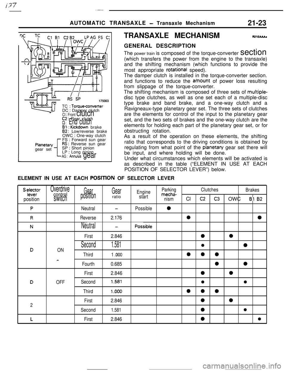
I IRS SP175003TC
: Torqueconverter
DC : Damper clutchCl : Front clutch
tPlanetan/
gear set
C2 : Rear clutchW : End clutchBl. : Kickdown brake82 : Low/reverse brake
OWC : One-way clutch
FS : Forward sun gearRS : Reverse sun gear
SP : Short pinion
LP : Long pinionAG : Annulus gearTRANSAXLE MECHANISM
fQlEMhGENERAL DESCRIPTION
The power train is composed of the torque-converter section
(which transfers the power from the engine to the transaxle)
and the shifting mechanism (which functions to provide the
most appropriate
rotational speed).
The damper clutch is installed in the torque-converter section.
and functions to reduce the ainount of power loss resulting
from slippage of the torque-converter.
The shifting mechanism is composed of three sets of multiple-
disc type clutches, as well as one set each of a multiple-disc
type brake and band brake, and a one-way clutch and a
Ravigneaux-type planetary gear set. The three sets of clutches
are the elements for control of the input to the planetary gear
set, and the two sets of brakes and the one-way clutch are the
elements for holding each part of the planetary gear set, or for
obstructing rotation.
As a result of the operation on these elements, the shifting
ratio that corresponds to the driving conditions is obtained by
regulating from what point of the
planetan/ gear set there will
be input, and where holding will be done.
Under what circumstances which elements will be activated is
as described in the table (“ELEMENT IN USE AT EACH
POSITION OF SELECTOR LEVER”) below.
ELEMENT IN USE AT EACH
POSITtON OF SELECTOR LEVER
S ylele~rOverdriveGearGearEngineParkingClutches
Brakescontrolmecha-
positionswitchpositionratiostartnismCl c2C3 OWC Bl 82
PNeutral-Possible0
RReverse2.17600
NNeutral-Possible
First
2.8460a
Second1.581l0DON
Third1 .ooo000
e
Fourth0.68500
First2.84600
DOFFSecond1.581ll
Third1 .ooo000
First2.846002
Second1.5810l
LFirst2.8460l
Page 248 of 391
21-24AUTOMATIC TRANSAXLE - Transaxle Mechanism
SELECT PATTERN
Select pattern refers to the indication of transaxle
positions to be manually selected by the driver. This
transaxie is provided with 6 positions: P-R-N-D-
2-L. The following contains the explanations of the
function of each position selected.
P-Parking
(1)
(2)
(3)
Each element does not operate at all. Therefore,the engine output is not transmitted to the
output shaft.
The output shaft is completely locked by mecha-
nical means. Therefore, the vehicle does not
move in forward or reverse direction.
The engine can be started.
R-Reverse
(1) The vehicle moves in reverse direction.
(2) The engine cannot be started.
N-Neutral
(1) The engine output is not transmitted to the
output shaft as in the case of
“P”(2) The engine can be started.
D-Drive
(1)
(2)
(3)Corresponding with the degree that the
accelerator pedal is pressed down (i.e. throttle
opening) and vehicle speed,
“D” automatically
shifts between forward 4 speeds. Note, howev-
er,’ that the forward 3 speeds are selected when
the overdrive control switch is OFF. The automa-tic shifting (up or down) is performed according
to the shift pattern shown in the illustration on
page 2
l-30.Driving-off is always performed in
1st gear.Kickdown refers to the downshift that is per-
formed if the accelerator pedal is pressed down
(4)
(5)when the vehicle is running. in
2nd. 3rd or 4t,.
gear. It is performed when the load exceeds the
downshift point.
This function
IS useful when the driver isaccelerating to pass another vehicle.
Engine brake does not function when the shift is
in
1st gear.
When the vehicle is stopped, shifting is made to
the
2nd gear to minimize creep and vibration.
Upon starting, shifting is made to
1st gear.
S-Second
(1)
(2)
(3)“2” automatically shifts between
1st and 2ndgears. This means no upshift to
3rd gear occurs.
Driving-off is always performed in
1st gear.
Downshift to
2nd or 3rd gear is performed by
selecting the“2” range while the vehicle is
running in
3,rd or 4th gear, when a speed lower
than the set value is reached.
(4)As in the case of the “D” range, engine brake
does not work when the shift is in
1st gear.
L-Lock-up
(1)
(2)
(3)While “L” (Lock-up) performs downshift from
2nd to 1st gear, it does not shift up the gear
from
1st to 2nd or 3rd. The enables what is_.called
“1st gear holding”.
Driving-off is always performed in
1st gear.
Engine brake functions in the case of this
1st
gear..By selecting the “L” range while the vehicle is
running in the
“0” or “2” range, downshift from4th to
3rd, 3rd to 2nd, or 2nd to 1st is performed
when the vehicle reaches the respective speed
prescribed for each gear.
Page 252 of 391
.-
I
21-28AUTOMATIC TRANSAXLE - Transaxle Mechanism
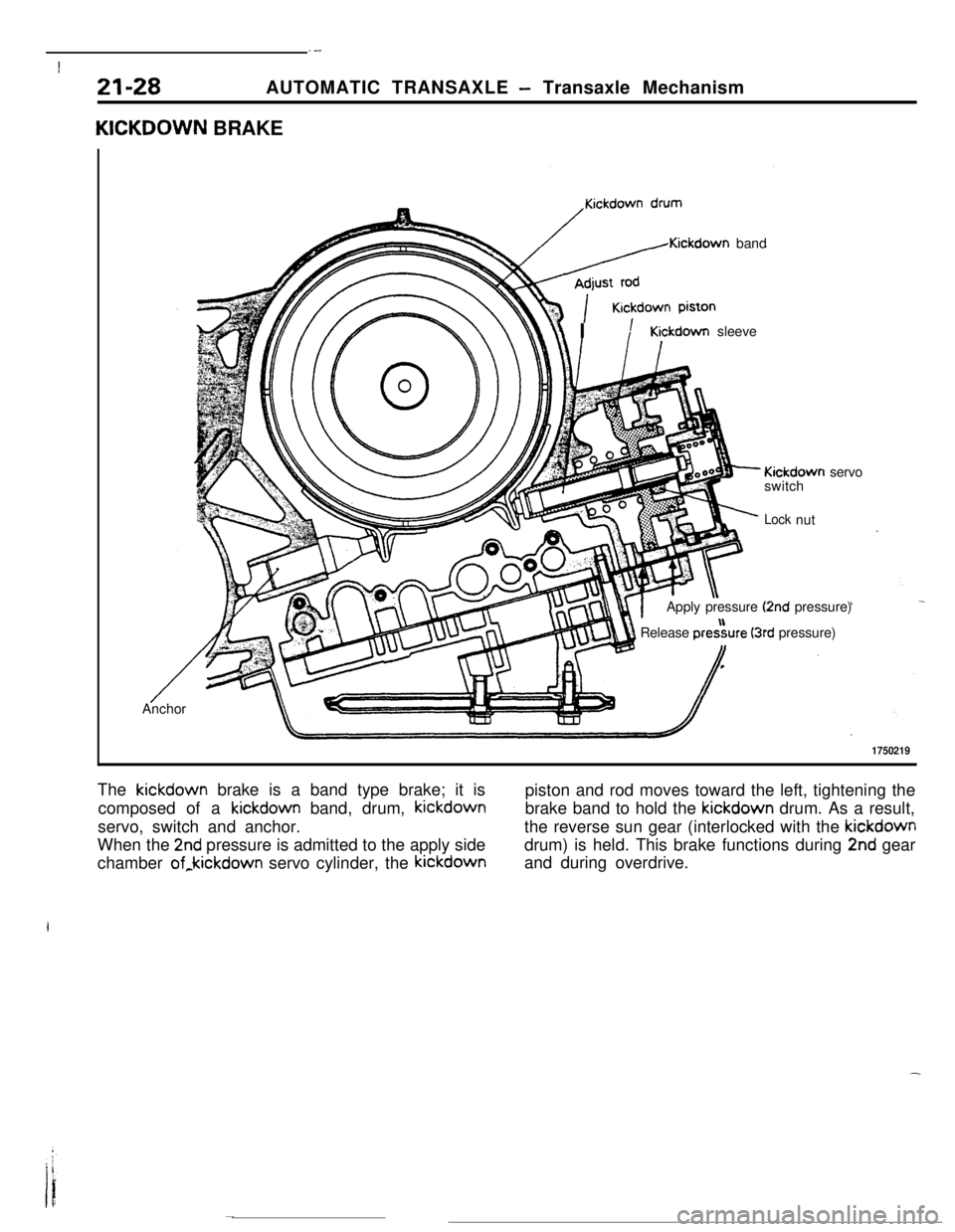
KICKDOWN BRAKE
/Kickdown band
r\\ IKickdown sleeve
- Kickdown servo
switch
;‘- Locknut
Apply pressure
(2nd pressure)
1 Release pre&re (3rd pressure)I,
/ --Anchor
1750219The kickdown brake is a band type brake; it is
piston and rod moves toward the left, tightening the
composed of a kickdown band, drum, kickdownbrake band to hold the kickdown drum. As a result,
servo, switch and anchor.the reverse sun gear (interlocked with the kickdown
When the
2nd pressure is admitted to the apply sidedrum) is held. This brake functions during 2nd gear
chamber of,kickdown servo cylinder, the kickdownand during overdrive.
Page 253 of 391
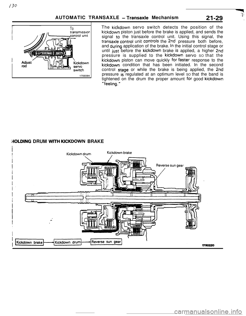
ToThe kickdown servo switch detects the position of thekickdown piston just before the brake is applied, and sends the
signal to the transaxle control unit. Using this signal, the
transaxle control unit controls the 2nd pressure both before,
and
during application of the brake. In the initial control stage or
until just before the kickdown brake
is applied, a higher 2ndpressure is supplied to the kickdown servo SO that thekickdown piston can move quickly for
faSter response to thekickdown condition that has been initiated. In the second
control
stage or while the brake is being applied, the 2nd
1750394pressure
is regulated at an optimum level SO that the band is
tightened on the drum the proper amount
for good kickdown
“feeling.”AUTOMATIC TRANSAXLE
- Transaxle MechanismY$21-29
,
ilOLDING DRUM WITH KICKDOWN BRAKE
Page 254 of 391
21-30AUTOMATIC TRANSAXLE - Transaxle Mechanism
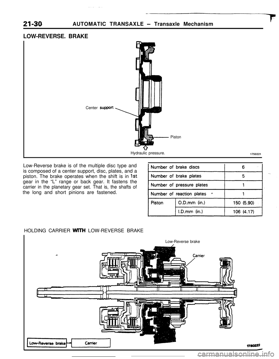
LOW-REVERSE. BRAKECentersupport
Hydraulic pressure.
Piston1750221
Low-Reverse brake is of the multiple disc type and
is composed of a center support, disc, plates, and a
piston. The brake operates when the shift is in
1stgear in the “L” range or back gear. It fastens the
carrier in the planetary gear set. That is, the shafts ofthe long and short pinions are fastened.
HOLDING CARRIER WITH LOW-REVERSE BRAKE
rLow-Reverse brake
Low-Reverse brake
Page 256 of 391
21-32AUTOMATIC TRANSAXLE - Transaxle Mechanism
PLANETARY GEAR
-.., ‘~ ~,.~.“.,
Reverse sun gear\ParkIng sprag
Carrier\
I\
i
\
Outer race.-End clutch shaftLow/reverse brake’s hub
Short pmlon17502L
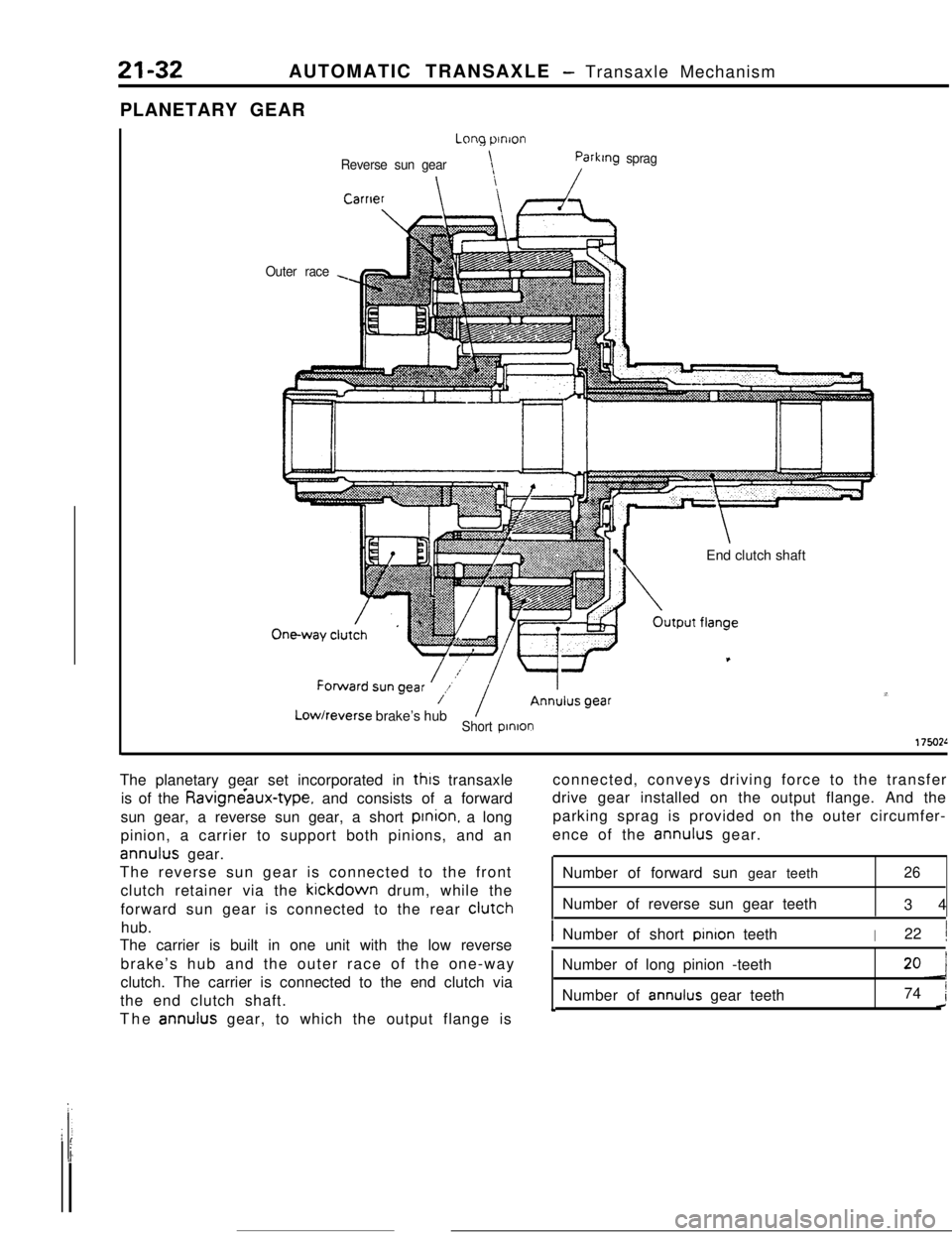
The planetary gear set incorporated in
thus transaxle
is of the Ravigne’aux-type, and consists of a forward
sun gear, a reverse sun gear, a short prnion. a long
pinion, a carrier to support both pinions, and an
annulus gear.
The reverse sun gear is connected to the front
clutch retainer via the
kickdown drum, while the
forward sun gear is connected to the rear
clutchhub.
The carrier is built in one unit with the low reverse
brake’s hub and the outer race of the one-way
clutch. The carrier is connected to the end clutch via
the end clutch shaft.
The
annulus gear, to which the output flange isconnected, conveys driving force to the transfer
drive gear installed on the output flange. And the
parking sprag is provided on the outer circumfer-
ence of the
annulus gear.
Number of forward sun gear teeth
Number of reverse sun gear teeth
2634
INumber of short pinron teethI22 1Number of long pinion -teeth
Number of
annulus gear teeth74 1c-’
Page 257 of 391
AUTOMATIC TRANSAXLE - Transaxle Mechanism21-33
POWER FLOW
T GEAR (“D” and ‘2” ranges)
Short
DinionCarrier
IForward sun gear
IOne-way clutch
IAnn&s gear
Rear clutch
-1Long pinioniransfer
drive gear
, Idler gear
Transfer* driven gear
17!50057
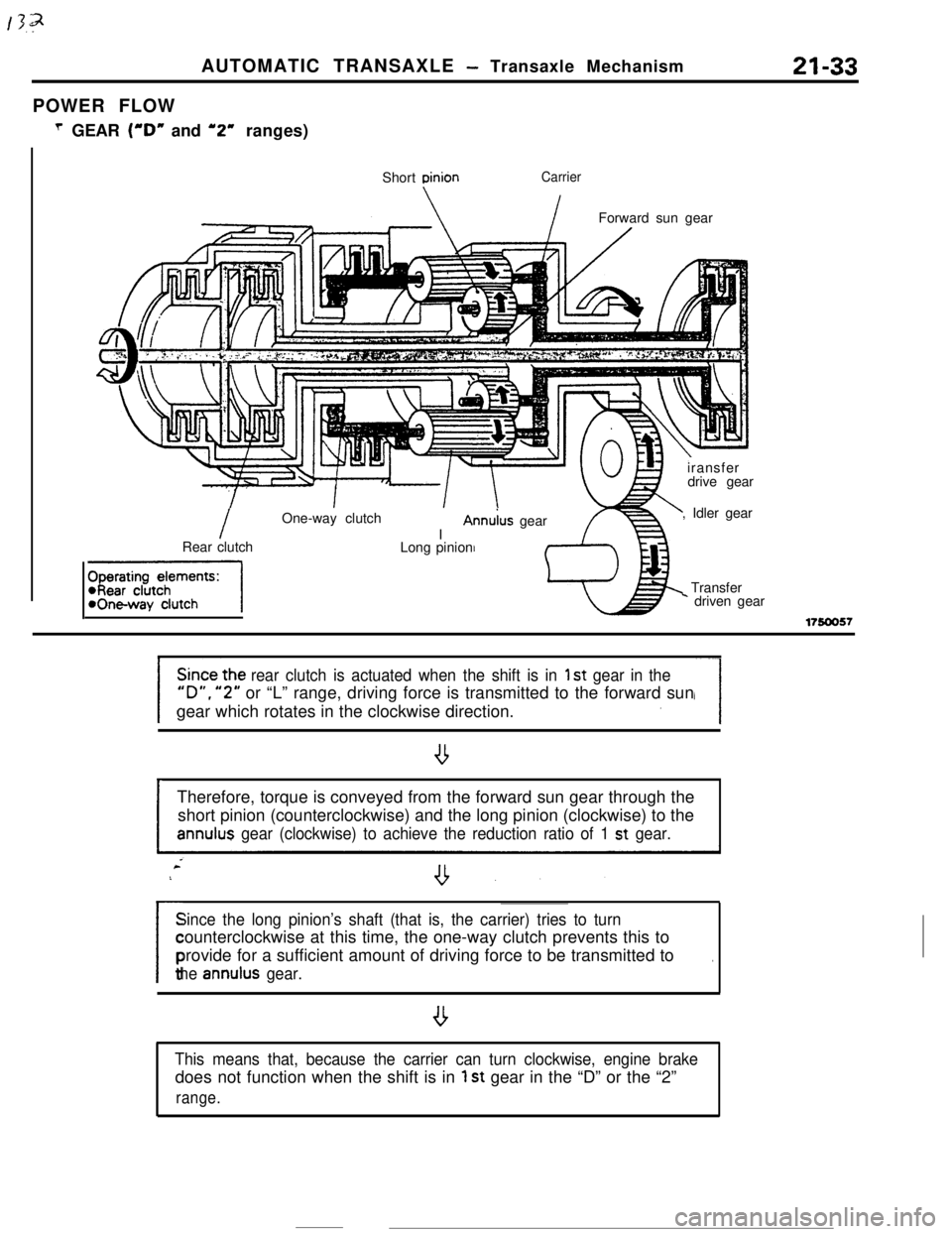
rear clutch is actuated when the shift is in 1 st gear in the
“D”. “2” or “L” range, driving force is transmitted to the forward sun
gear which rotates in the clockwise direction.
ITherefore, torque is conveyed from the forward sun gear through the
short pinion (counterclockwise) and the long pinion (clockwise) to theannulus gear (clockwise) to achieve the reduction ratio of 1 st gear.
Since the long pinion’s shaft (that is, the carrier) tries to turn
/counterclockwise at this time, the one-way clutch prevents this to
provide for a sufficient amount of driving force to be transmitted to
.
the annulus gear.
,
This means that, because the carrier can turn clockwise, engine brakedoes not function when the shift is in
1 st gear in the “D” or the “2”
range.
Page 258 of 391
_____--._- .21-34AUTOMATIC TRANSAXLE
- Transaxde Mechanism
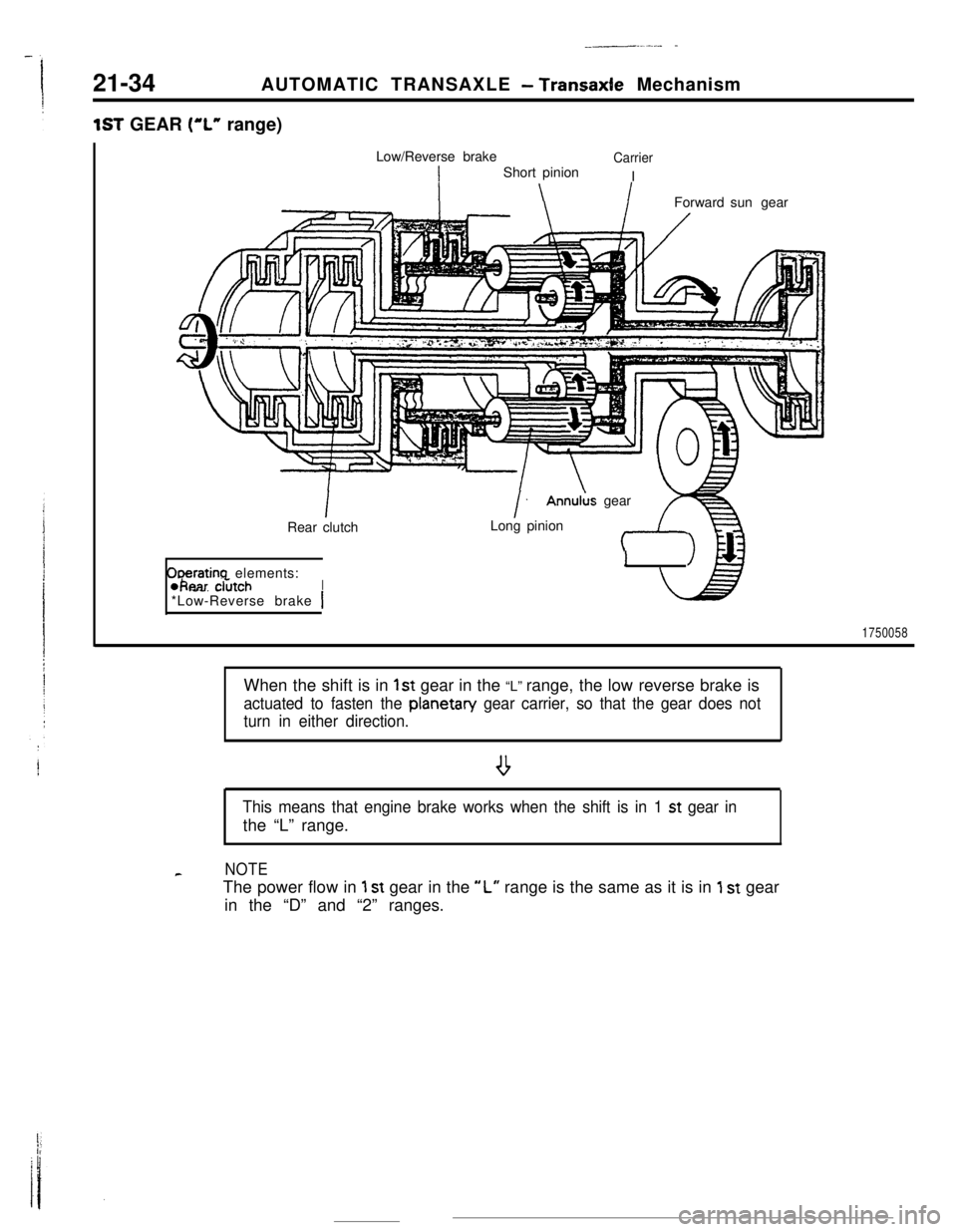
1ST GEAR (“L” range)
Low/Reverse brake
Carrier
IShort pinion
I
Forward sungearAnnulus gear
ODeratina elements:&ear clkch. .--. _.-__.I*Low-Reverse brake
1
I>\\PRear clutchLong pinion
1750058When the shift is in
1st gear in the “L” range, the low reverse brake is
actuated to fasten the planetan/ gear carrier, so that the gear does not
turn in either direction.
.
This means that engine brake works when the shift is in 1 st gear inthe “L” range.
cNOTEThe power flow in
1 st gear in the “L” range is the same as it is in 1 st gear
in the “D” and “2” ranges.
Page 259 of 391
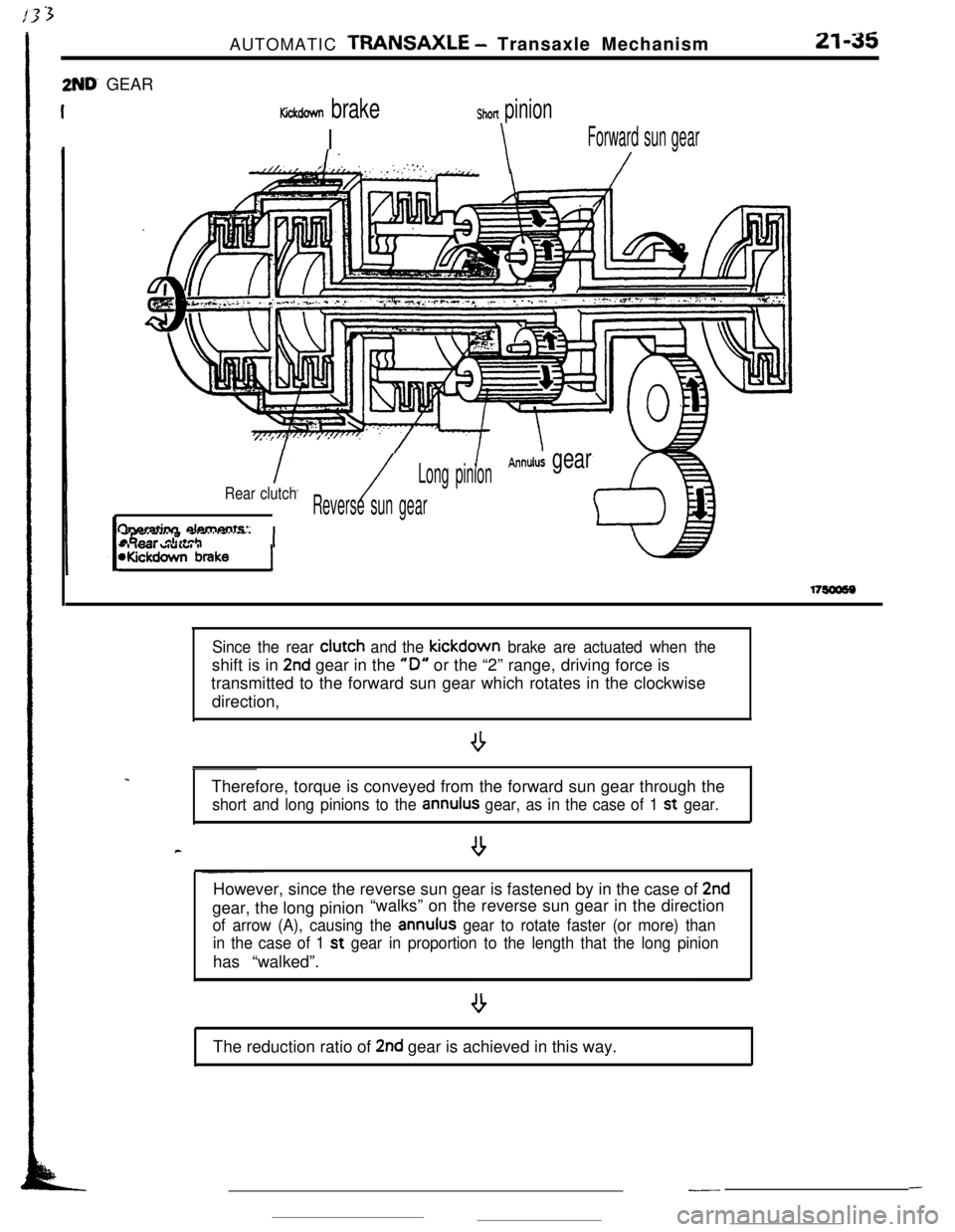
2ND’ GEARAUTOMATIC
TRANSAXLE - Transaxle Mechanism21-35
Kickdown brake
I
Shon pinion
\Forward sun gear
1.//LT.//. , ,’ .‘,,i.:,;:.:‘.,.‘,\/
/
Annulus gearLong pinion
Rear clutch/Reverse sun gear
fharatinn damants:
-, IWI WUIUI IWickdown brakeI
.
c
Since the rear clutch and the kickdown brake are actuated when theshift is in
2nd gear in the “0” or the “2” range, driving force is
transmitted to the forward sun gear which rotates in the clockwise
direction,
Therefore, torque is conveyed from the forward sun gear through the
short and long pinions to the annulus gear, as in the case of 1 st gear.
--However, since the reverse sun gear is fastened by in the case of
2ndgear, the long pinion“walks” on the reverse sun gear in the direction
of arrow (A), causing the annulus gear to rotate faster (or more) than
in the case of 1 st
gear in proportion to the length that the long pinionhas “walked”.
The reduction ratio of
2nd gear is achieved in this way.
---