lock MITSUBISHI ECLIPSE 1990 User Guide
[x] Cancel search | Manufacturer: MITSUBISHI, Model Year: 1990, Model line: ECLIPSE, Model: MITSUBISHI ECLIPSE 1990Pages: 391, PDF Size: 15.27 MB
Page 64 of 391
__ .__-.... . - -----8-12ELECTRICAL
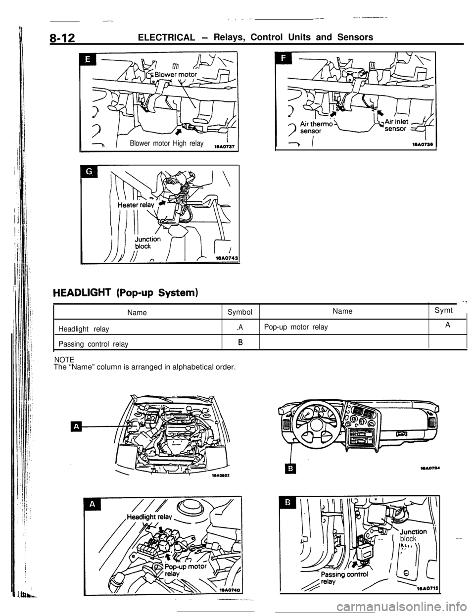
-Relays, Control Units and Sensors
Blower motor High relay,,,A,
HEADLIGHT (Pop-up System)-7
NameSymbolNameSymt
Headlight relay.APop-up motor relayA
Passing control relayB
NOTEThe “Name” column is arranged in alphabetical order.
+Junction \-- 1block\-
Page 65 of 391
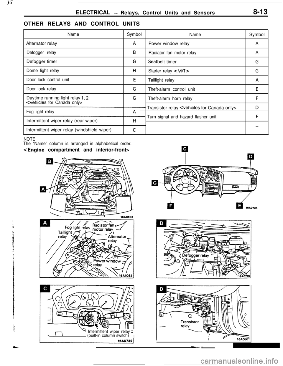
ELECTRICAL- Relays, Control Units and Sensors8-13OTHER RELAYS AND CONTROL UNITS
NameSymbol
NameSymbol
Alternator relay
APower window relay
A
Defogger relayBRadiator fan motor relayA
Defogger timer
GSeatbelt timerG
Dome light relayHStarter relay
Door lock control unitETaillight relayA
Door lock relayGTheft-alarm control unitEDaytime running light relay
1,2G
Fog light relay- Transistor relay
Intermittent wiper relay (rear wiper)
p Turn signal and hazard flasher unitFH-Intermittent wiper relay (windshield wiper)
C
NOTEThe “Name” column is arranged in alphabetical order.
Y Intermittent wiper relayz
(built-in column switch)
I
Page 69 of 391
ELECTRICAL - Lighting8-17
Front turnsignal light
(Optical horn)
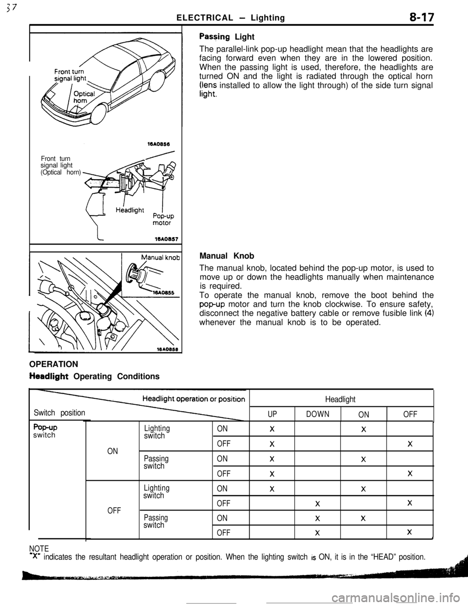
Pas+ing Light
The parallel-link pop-up headlight mean that the headlights are
facing forward even when they are in the lowered position.
When the passing light is used, therefore, the headlights are
turned ON and the light is radiated through the optical horn
rr,“;; installed to allow the light through) of the side turn signal
OPERATION
tieadlight Operating ConditionsManual Knob
The manual knob, located behind the pop-up motor, is used to
move up or down the headlights manually when maintenance
is required.
To operate the manual knob, remove the boot behind the
popup motor and turn the knob clockwise. To ensure safety,
disconnect the negative battery cable or remove fusible link
(4)whenever the manual knob is to be operated.
Switch positionUP
Headlight
DOWN
ONOFF
f%+Pswitch
ON
OFF
Lightingswitch
Passingswitch
Lightingswitch
Passingswitch
ONXX
OFF
XX
ONXX
OFF
XX
ONXX
OFFXX
ONXX
OFF
XXI
NOTE
‘X” indicates the resultant headlight operation or position. When the lighting switch is ON, it is in the “HEAD” position.
Page 70 of 391
8-18ELECTRICAL - Lighting
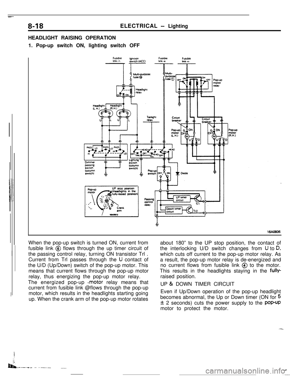
HEADLIGHT RAISING OPERATION
1. Pop-up switch ON, lighting switch OFF
When the pop-up switch is turned ON, current from
fusible link @ flows through the up timer circuit of
the passing control relay, turning ON transistor Trl .
Current from Trl passes through the
U contact of
the U/D (Up/Down) switch of the pop-up motor. This
means that current flows through the pop-up motor
relay, thus energizing the pop-up motor relay.
The energized pop-up
*motor relay means that
current from fusible link @flows through the pop-up
motor, which results in the headlights starting going
up. When the crank arm of the pop-up motor rotatesabout 180” to the UP stop position, the contact of
the interlocking U/D switch changes from
U to D,which cuts off current to the pop-up motor relay. As
a result, the pop-up motor relay is de-energized and
no current flows from fusible link @ to the motor.
This results in the headlights staying in the fully-
raised position.
UP
& DOWN TIMER CIRCUIT
Even if Up/Down operation of the pop-up headlight
becomes abnormal, the Up or Down timer (ON for
5
f 2 seconds) cuts the power supply to the POP-UPmotor to protect the motor.
I
jj
bib,-.-.+. -- ------.__
Page 72 of 391
_ -. _ -.__-ELECTRICAL
- Lighting
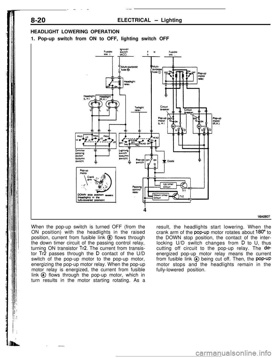
HEADLIGHT LOWERING OPERATION
1. Pop-up switch from ON to OFF, lighting switch OFF
FUslMelgnnlonswlchFlmk 1r- -!IACCI
Ar
Fusablehnk .
4
When the pop-up switch is turned OFF (from the
ON position) with the headlights in the raised
position, current from fusible link @ flows through
the down timer circuit of the passing control relay,
turning ON transistor
Tr2. The current from transis-
tor
Tr2 passes through the D contact of the U/D
switch of the pop-up motor to the pop-up motor,
energizing the pop-up motor relay. When the pop-up
motor relay is energized, the current from fusible
link @ flows through the pop-up motor, which in
turn results in the motor starting rotating. As a
.-.-result, the headlights start lowering. When the
crank arm of the
popup motor rotates about 180” to
the DOWN stop position, the contact of the inter-
locking U/D switch changes from
D to U, thus
cutting off circuit to the pop-up relay. The
deenergized pop-up motor relay means the current
from fusible link @ being cut off. Then, the
popUPmotor stops and the headlights remain in the
fully-lowered position.
Page 75 of 391
ELECTRICAL- Ermine Electrical8-23
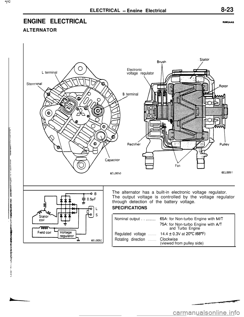
ENGINE ELECTRICALRoaGAABALTERNATOR
L terminal\Stern
Electronicvoltage regulator
B terminal/
Rectlfber‘i ‘IT
VFantl
GEL0051The alternator has a built-in electronic voltage regulator.
The output voltage is controlled by the voltage regulator
through detection of the battery voltage.
SPECIFICATIONS
Nominal output . . .._...._..65A: for Non-turbo Engine with M/T
75A: for Non-turbo Engine with AAand Turbo Engine
Regulated voltage. . . . . . . .14.4 f 0.3V at 20°C (68°F)
Rotating direction. . . . . . . .Clockwise(viewed from pulley side)
-
Page 76 of 391
.-
8-24ELECTRICAL- Engine Electrical
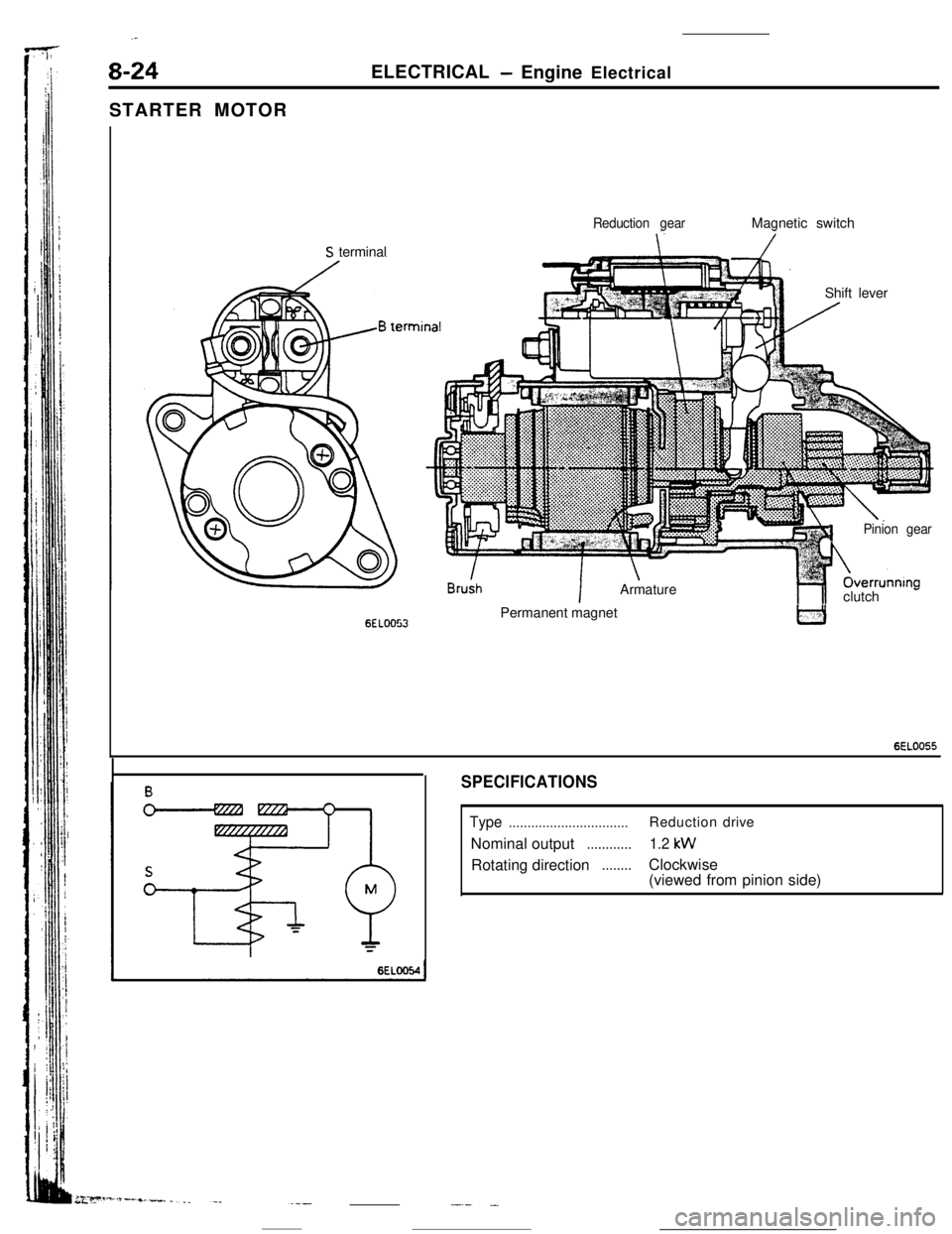
STARTER MOTOR
Reduction gearMagnetic switch
S terminal
Shift lever
6ELOO53
!n
IArmature
1Pinion gearOverrunnIng
hlclutch -Permanent magnet
6EL0055
SPECIFICATIONS
Type................................Reductiondrive
Nominal output
............1.2 kWRotating direction
........Clockwise
(viewed from pinion side)
-.- .-
Page 80 of 391
8-28ELECTRICAL- Engine Electrical
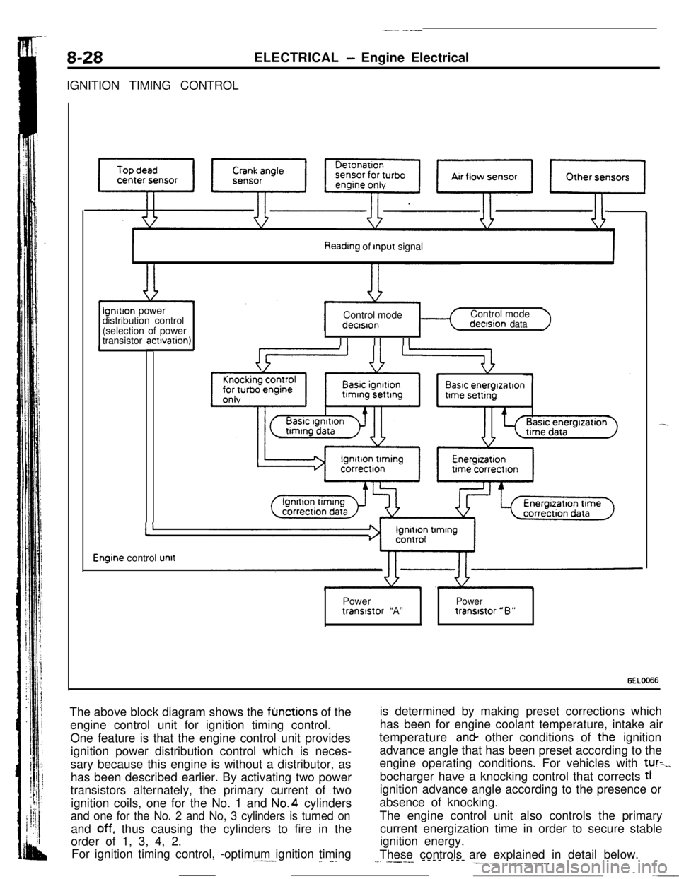
IGNITION TIMING CONTROL
Reading of Input signallgnitlon power
distribution control
(selection of power
transistor actlvatlon)Control mode
I II II IControl mode
dectsion data
Basic energlzatlon
I’
Engine control unitPower
Powertranststor “A”tranststor “B”
6ELOO66The above block diagram shows the
fljnctions of the
engine control unit for ignition timing control.
One feature is that the engine control unit provides
ignition power distribution control which is neces-
sary because this engine is without a distributor, as
has been described earlier. By activating two power
transistors alternately, the primary current of two
ignition coils, one for the No. 1 and No.4 cylinders
and one for the No. 2 and No, 3 cylinders is turned onand
off. thus causing the cylinders to fire in the
order of 1, 3, 4, 2.
For ignition timing control, -optimum ignition timing.^--_
_. -.is determined by making preset corrections which
has been for engine coolant temperature, intake air
temperature an& other conditions of the ignition
advance angle that has been preset according to the
engine operating conditions. For vehicles with
tur=_.bocharger have a knocking control that corrects tl
ignition advance angle according to the presence or
absence of knocking.
The engine control unit also controls the primary
current energization time in order to secure stable
ignition energy.
These controls are explained in detail below.
--. .----- ---- --- ___. .-. ___.,.__
Page 84 of 391
8-32ELECTRICAL - Theft-alarm System
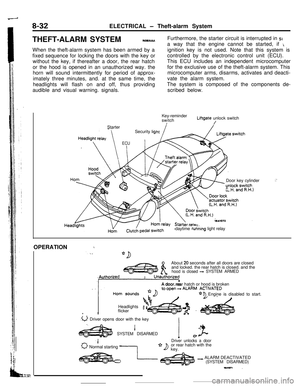
THEFT-ALARM SYSTEM
NOOIAAAWhen the theft-alarm system has been armed by a
fixed sequence for locking the doors with the key or
without the key, if thereafter a door, the rear hatch
or the hood is opened in an unauthorized way. the
horn will sound intermittently for period of approx-
imately three minutes, and. at the same time, the
headlights will flash on and off, thus providing
audible and visual warning. signals.Furthermore, the starter circuit is interrupted in SIa way that the engine cannot be started, if
‘Lignition key is not used. Note that this system is
controlled by the electronic control unit (ECU).
This ECU includes an independent microcomputer
for the exclusive use of the theft-alarm system. This
microcomputer arms, disarms, activates and deacti-
vate the alarm system.
The system is composed of the components de-
scribed below.
Key-reminder
switchLiftgate unlock switch
!/Starter
Door key cylinder
”daytime running light relay Security
lig
ECU
I
HornOPERATION
iAbout
20 seconds after all doors are closed
and locked. the rear hatch is closed. and the
hood is closed + SYSTEM ARMED
. .‘11A door rear hatch or hood is brokenALARM ACT,“ATED
* n Engine is disabled to start.
Headlights
Iflicker
*.
.u Driver opens door with the key
I.l .
SYSTEM DISARMEDI J-0
-IDriver unlocks a door
0 Normal starting -1or rear hatch with the*D key.
- ALARM DEACTIVATED(SYSTEM DISARMED)
Page 85 of 391
ELECTRICAL - Theft-alarm System8-33ARMING THE SYSTEM
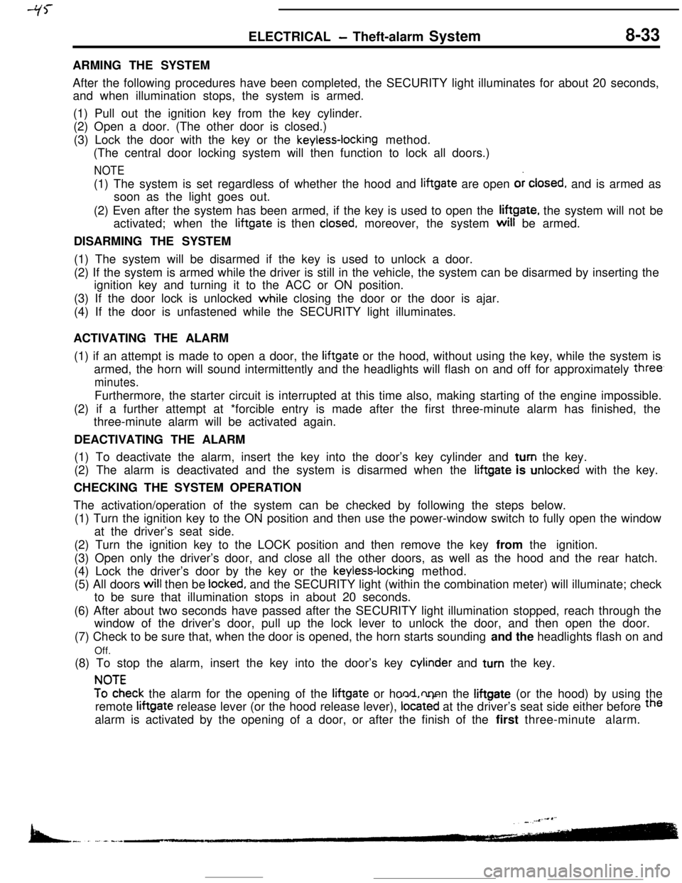
After the following procedures have been completed, the SECURITY light illuminates for about 20 seconds,
and when illumination stops, the system is armed.
(1) Pull out the ignition key from the key cylinder.
(2) Open a door. (The other door is closed.)
(3) Lock the door with the key or the
keyless-locking method.
(The central door locking system will then function to lock all doors.)
NOTE(1) The system is set regardless of whether the hood and liftgate are open or
closed, and is armed as
soon as the light goes out.
(2) Even after the system has been armed, if the key is used to open the liftgate, the system will not be
activated; when the liftgate is then
closed, moreover, the system will be armed.
DISARMING THE SYSTEM
(1) The system will be disarmed if the key is used to unlock a door.
(2) If the system is armed while the driver is still in the vehicle, the system can be disarmed by inserting the
ignition key and turning it to the ACC or ON position.
(3) If the door lock is unlocked while closing the door or the door is ajar.
(4) If the door is unfastened while the SECURITY light illuminates.
ACTIVATING THE ALARM
(1) if an attempt is made to open a door, the liftgate or the hood, without using the key, while the system is
armed, the horn will sound intermittently and the headlights will flash on and off for approximately
three,
minutes.Furthermore, the starter circuit is interrupted at this time also, making starting of the engine impossible.
(2) if a further attempt at *forcible entry is made after the first three-minute alarm has finished, the
three-minute alarm will be activated again.
DEACTIVATING THE ALARM
(1) To deactivate the alarm, insert the key into the door’s key cylinder and turn the key.
(2) The alarm is deactivated and the system is disarmed when the iiftgate is unlocked with the key.
CHECKING THE SYSTEM OPERATION
The activation/operation of the system can be checked by following the steps below.
(1) Turn the ignition key to the ON position and then use the power-window switch to fully open the window
at the driver’s seat side.
(2) Turn the ignition key to the LOCK position and then remove the key from the ignition.
(3) Open only the driver’s door, and close all the other doors, as well as the hood and the rear hatch.
(4) Lock the driver’s door by the key or the
keyless-locking method.
(5) All doors will then be
locked, and the SECURITY light (within the combination meter) will illuminate; check
to be sure that illumination stops in about 20 seconds.
(6) After about two seconds have passed after the SECURITY light illumination stopped, reach through the
window of the driver’s door, pull up the lock lever to unlock the door, and then open the door.
(7) Check to be sure that, when the door is opened, the horn starts sounding and the headlights flash on and
Off.
(8) To stop the alarm, insert the key into the door’s key cylinder and turn the key.
!?iEeck the alarm for the opening of the liftgate or hood open the liftgate (or the hood) by using the
remote liftgate release lever (or the hood release lever),
located at the driver’s seat side either before the
alarm is activated by the opening of a door, or after the finish of the first three-minute alarm.