MITSUBISHI ECLIPSE 1991 Owners Manual
ECLIPSE 1991
MITSUBISHI
MITSUBISHI
https://www.carmanualsonline.info/img/19/57104/w960_57104-0.png
MITSUBISHI ECLIPSE 1991 Owners Manual
Page 949 of 1216
AUTOMATIC TRANSAXLE - Transaxle Assemblv 21-255
Spacer
1700108
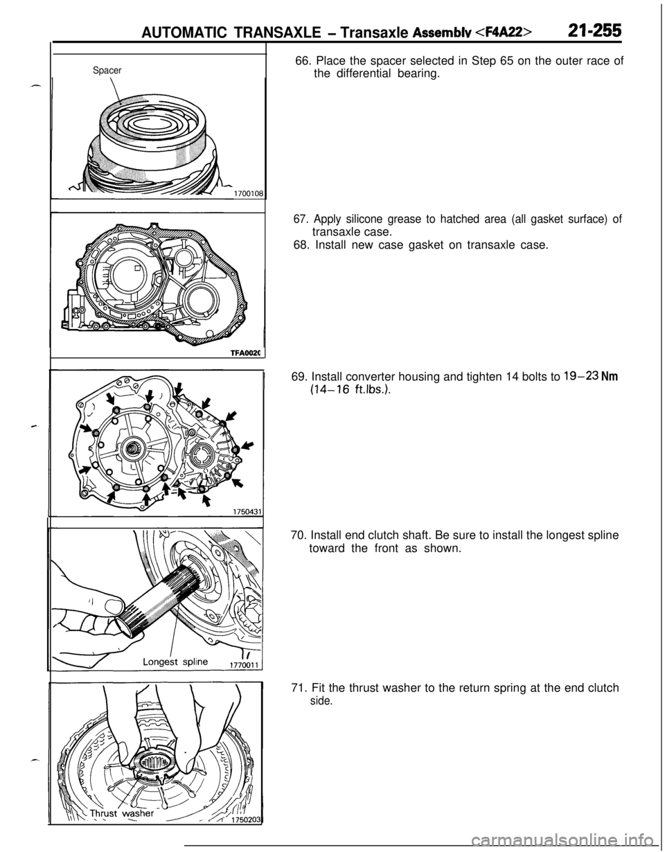
TFA002066. Place the spacer selected in Step 65 on the outer race of
the differential bearing.
67. Apply silicone grease to hatched area (all gasket surface) oftransaxle case.
68. Install new case gasket on transaxle case.
69. Install converter housing and tighten 14 bolts to
19-23 Nm
(14-16 ft.Ibs.).70. Install end clutch shaft. Be sure to install the longest spline
toward the front as shown.
71. Fit the thrust washer to the return spring at the end clutch
side.
Page 961 of 1216
AUTOMATIC TRANSAXLE - Transaxle Assembly 21-26772
58
qo T9I
46
8\ 43
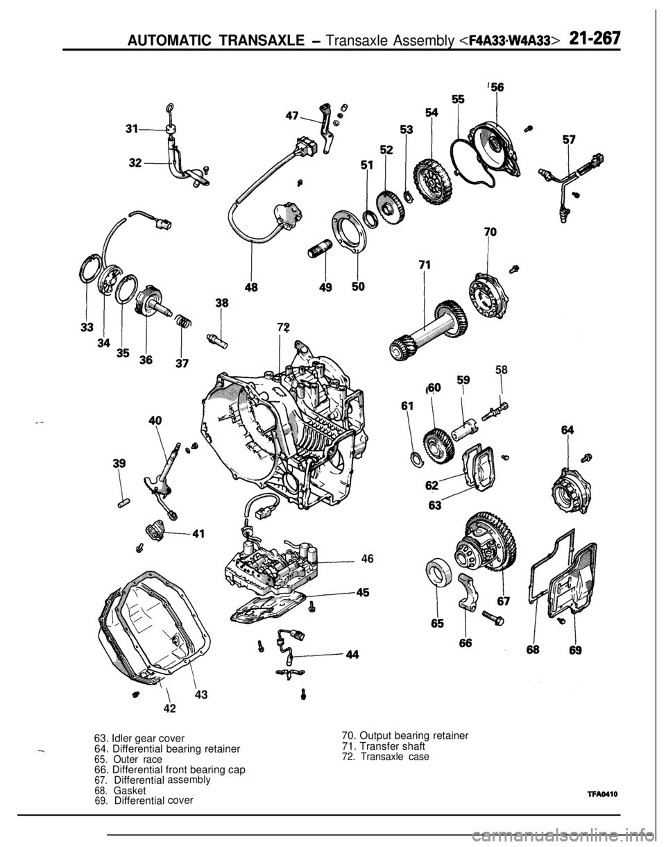
4270. Output bearing retainer
71. Transfer shaft
72. Transaxle case63. Idler gear cover
64. Differential bearing retainer65.Outer race66. Differential front bearing cap
67.Differentialassembly
68.Gasket69.DifferentialcoverTFAO410
Page 963 of 1216
AUTOMATIC TRANSAXLE - Transaxle Assembly 21-269
,56
,1
I--
,.
31
32
36
37
//46
-a58 -
6669
eI42
TFA0411
-.63.idler
gear cover
69.Differential
cover
64. Differential bearing retainer
65.Spacer70. Output bearing retainer71.Center differential assembly66. Differential front bearing cap
72. Center bearing retainer
67.Differential assembly73.Stopper ring68.Gasket74.Viscous coupling unit
75. Center bearing retainer76.Front output shaft
77. Rear output shaft
78.Transaxle case
Page 966 of 1216
21-272 AUTOMATIC TRANSAXLE -Transaxle Assembly 15. Remove the set screw in the manual control shaft and pull
out the manual control shaft assembly.
16. Remove the detent assembly.
As?17. Remove the differential cover and gasket.
18. Remove the differential front bearing cap.
19. Remove the differential bearing retainer, spacer and outer
race
(FWD only).
20. Remove the differential assembly.
Page 973 of 1216
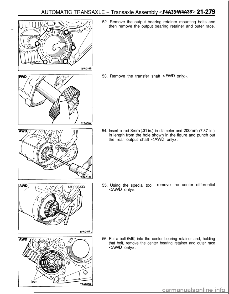
ITFA014952. Remove the output bearing retainer mounting bolts and
then remove the output bearing retainer and outer race.
// TFAOlSOl53. Remove the transfer shaft .
54. Insert a rod 8mm (.31 in.) in diameter and 200mm (7.87 in.)in length from the hole shown in the figure and punch out
the rear output shaft
. AUTOMATIC TRANSAXLE
- Transaxle Assembly 21-279
TFA0152 .j55. Using the special tool,remove the center differential
.
56. Put a bolt (M6) into the center bearing retainer and, holding
that bolt, remove the center bearing retainer and outer race
.
Page 977 of 1216
AUTOMATIC TRANSAXLE - Transaxle Assemblv 21-283
6990936TFA016411. Using a bearing puller, support the viscous coupling and
insert in the case. Then, install the stopper ring
only>.12. Using the special tool, install the outer race in the center
bearing retainer.
.13. Install the center bearing retainer stopper bolt
only>.Center bearing retainer stopper bolt:
4-6 Nm (3-4
ft.lbs.)14. Install the center bearing retainer so the projection of the
stopper bolt fits in the groove of the center bearing retainer
.
15. Install the special tool in the center differential and install
the center differential in the transaxle case
.
Page 987 of 1216
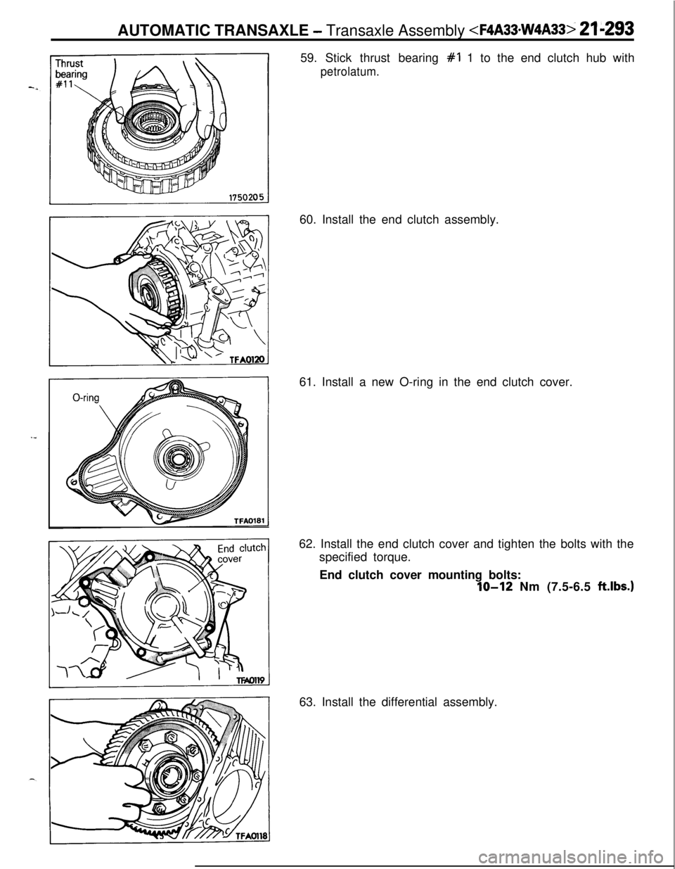
AUTOMATIC TRANSAXLE - Transaxle Assembly
#I 1 to the end clutch hub with
petrolatum.60. Install the end clutch assembly.
61. Install a new O-ring in the end clutch cover.
62. Install the end clutch cover and tighten the bolts with the
specified torque.
End clutch cover mounting bolts:
IO-12 Nm (7.5-6.5 ftlbs.)63. Install the differential assembly.
Page 988 of 1216
21-294 AUTOMATIC TRANSAXLE - Transaxle Assemblv
‘/TFAOl16
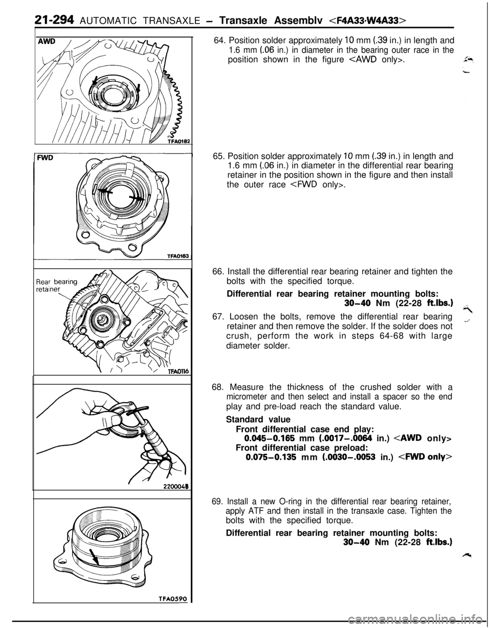
TFA0590-64. Position solder approximately
10 mm (39 in.) in length and
1.6 mm (06 in.) in diameter in the bearing outer race in theposition shown in the figure
.
65. Position solder approximately
10 mm (39 in.) in length and
1.6 mm
(.06 in.) in diameter in the differential rear bearing
retainer in the position shown in the figure and then install
the outer race .
66. Install the differential rear bearing retainer and tighten the
bolts with the specified torque.
Differential rear bearing retainer mounting bolts:
30-40 Nm (22-28 ft.lbs.167. Loosen the bolts, remove the differential rear bearing
retainer and then remove the solder. If the solder does not
crush, perform the work in steps 64-68 with large
diameter solder.
68. Measure the thickness of the crushed solder with a
micrometer and then select and install a spacer so the endplay and pre-load reach the standard value.
Standard value
Front differential case end play:
0.045-0.165 mm (.0017-.0064 in.)
Front differential case preload:
0.075-0.135 mm (.0030-.0053 in.)
69. Install a new O-ring in the differential rear bearing retainer,
apply ATF and then install in the transaxle case. Tighten thebolts with the specified torque.
Differential rear bearing retainer mounting bolts:
30-40 Nm (22-28 ft.lbs.)
Page 989 of 1216
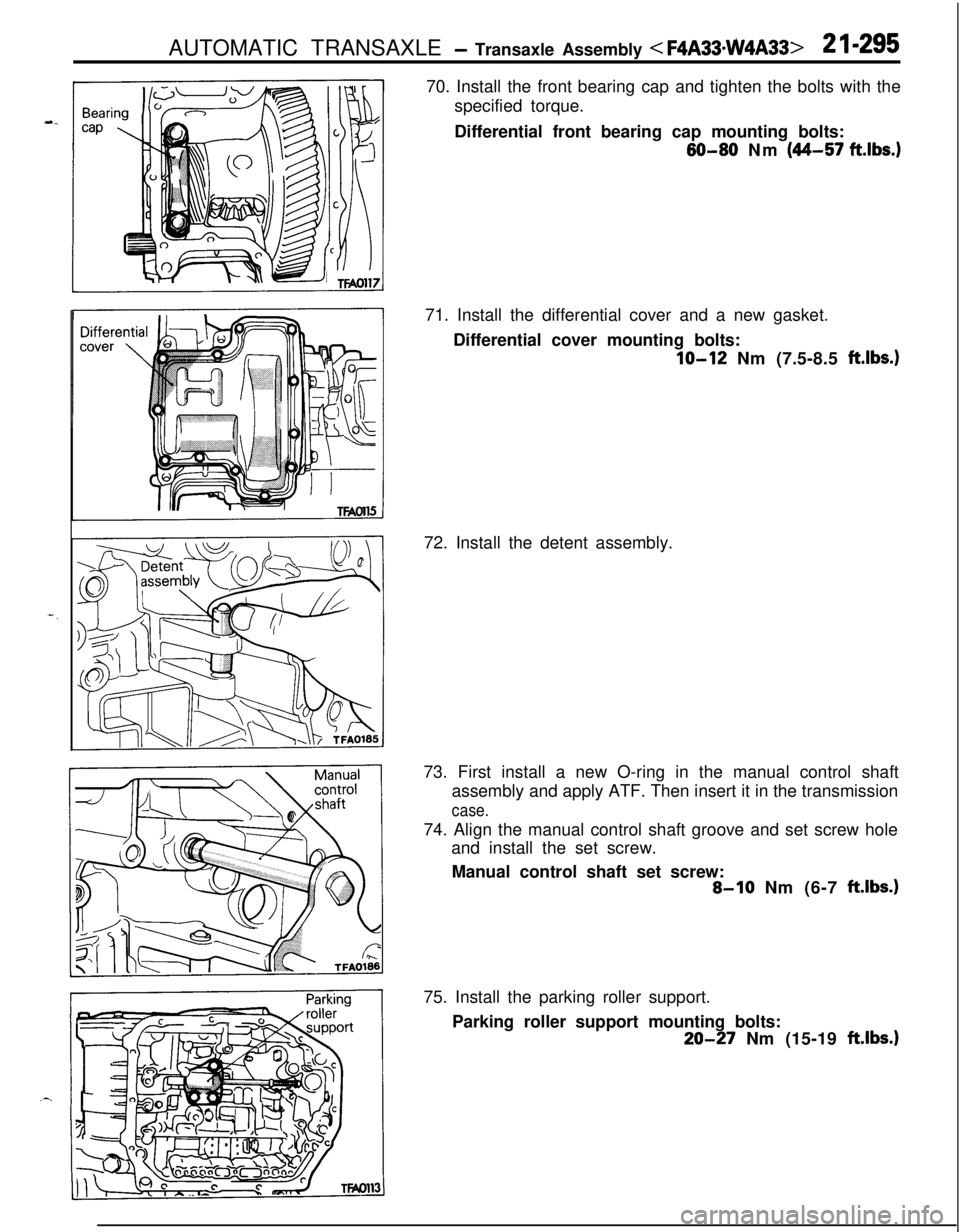
AUTOMATIC TRANSAXLE - Transaxle Assembly < F4A33*w4A33>2 I-29570. Install the front bearing cap and tighten the bolts with the
specified torque.
Differential front bearing cap mounting bolts:
60-80 Nm (44-57 ft.lbs.)71. Install the differential cover and a new gasket.
Differential cover mounting bolts:
IO-12 Nm (7.5-8.5 ft.lbs.)72. Install the detent assembly.
73. First install a new O-ring in the manual control shaft
assembly and apply ATF. Then insert it in the transmission
case.74. Align the manual control shaft groove and set screw hole
and install the set screw.
Manual control shaft set screw:
8-10 Nm (6-7 ft.lbs.)75. Install the parking roller support.
Parking roller support mounting bolts:
20-27 Nm (15-19 ft.lbs.1
Page 1013 of 1216
AUTOMATIC TRANSAXLE - Differential
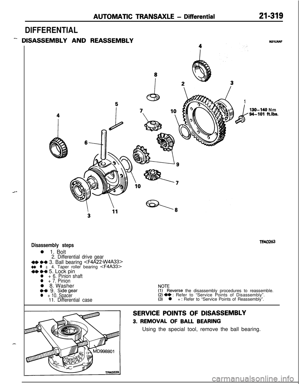
DIFFERENTIAL
- DISASSEMBLY AND REASSEMBLYNZlLNAF
1
k
130-140 Nm34-101 ft.lbs.
TWO263Disassembly stepsl 1. Bolt
2. Differential drive gear
4e e4 3. Ball bearing +e l a4. Taper roller bearing *ee+ 5. Lock pinl + 6. Pinion shaft
l + 7. Pinionl 8. Washer
e+ 9. Sidegearl + 10. SpacerIl. Differential case
$?everse the disassembly procedures to reassemble.(2) +e : Refer to “Service Points of Disassembly”.(3) l + : Refer to “Service Points of Reassembly”.
SERVICE POINTS OF DISASSEMBLY
3. REMOVAL OF BALL BEARINGUsing the special tool, remove the ball bearing.
