differential MITSUBISHI ECLIPSE 1991 Manual PDF
[x] Cancel search | Manufacturer: MITSUBISHI, Model Year: 1991, Model line: ECLIPSE, Model: MITSUBISHI ECLIPSE 1991Pages: 1216, PDF Size: 67.42 MB
Page 798 of 1216
21-104MANUAL TRANSAXLE
Piniongear
MD99881 2
MD998820
TFM0017
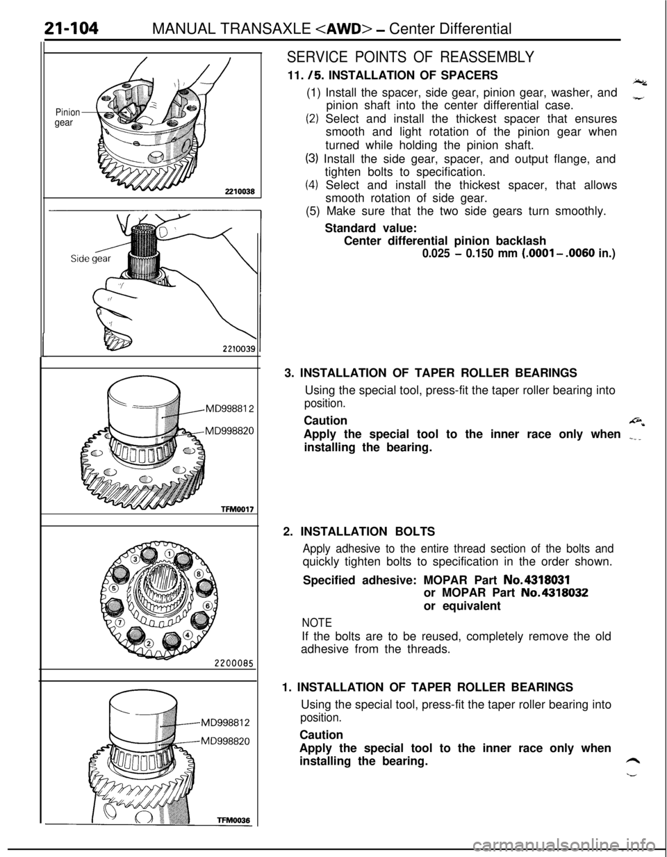
SERVICE POINTS OF REASSEMBLY11.
/5. INSTALLATION OF SPACERSI.(1) Install the spacer, side gear, pinion gear, washer, and
pinion shaft into the center differential case.
z
(2) Select and install the thickest spacer that ensures
smooth and light rotation of the pinion gear when
turned while holding the pinion shaft.
(3) Install the side gear, spacer, and output flange, and
tighten bolts to specification.
(4) Select and install the thickest spacer, that allows
smooth rotation of side gear.
(5) Make sure that the two side gears turn smoothly.
Standard value:
Center differential pinion backlash
0.025 - 0.150 mm (.OOOl - .0060 in.)3. INSTALLATION OF TAPER ROLLER BEARINGS
Using the special tool, press-fit the taper roller bearing into
position.Caution
@*Apply the special tool to the inner race only when
.___installing the bearing.
2. INSTALLATION BOLTS
Apply adhesive to the entire thread section of the bolts andquickly tighten bolts to specification in the order shown.
Specified adhesive: MOPAR Part No.4318031
or MOPAR Part No.4318032
or equivalent
NOTEIf the bolts are to be reused, completely remove the old
adhesive from the threads.
1. INSTALLATION OF TAPER ROLLER BEARINGS
Using the special tool, press-fit the taper roller bearing into
position.Caution
Apply the special tool to the inner race only when
installing the bearing.
6
h--
Page 800 of 1216
21-106MANUAL TRANSAXLE
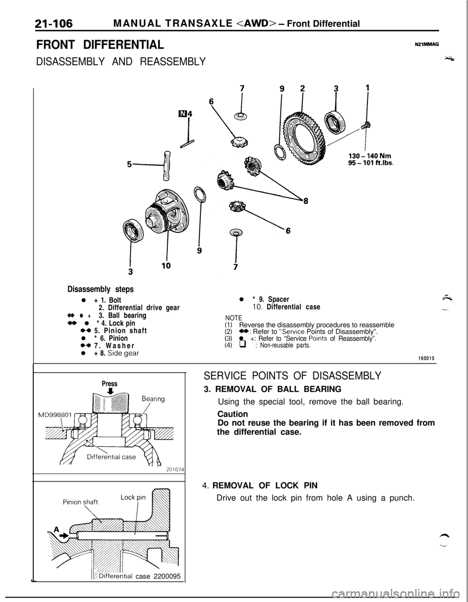
FRONT DIFFERENTIAL
DISASSEMBLY AND REASSEMBLY
NZIMMAG
i;&
Disassembly stepsl + 1. Bolt
2. Differential drive gear
** l +3. Ball bearing+* l * 4. Lock pinI)+ 5. Pinion shaft
l * 6. Pinion
I)+ 7. Washer
l + 8. Sidegear
95-lOl ft.lbs.l * 9. Spacer10. Differential case
NOTE(I)Reverse the disassembly procedures to reassemble(2)C*: Refer to “Service Points of Disassembly”.(3)l +: Refer to “Service Points of Reassembly”.(4)q : Non-reusable parts.
:&
-_-
160015
Press
teal case 2200095
SERVICE POINTS OF DISASSEMBLY3. REMOVAL OF BALL BEARING
Using the special tool, remove the ball bearing.
Caution
Do not reuse the bearing if it has been removed from
the differential case.
4. REMOVAL OF LOCK PIN
Drive out the lock pin from hole A using a punch.
Page 801 of 1216
MANUAL TRANSAXLE
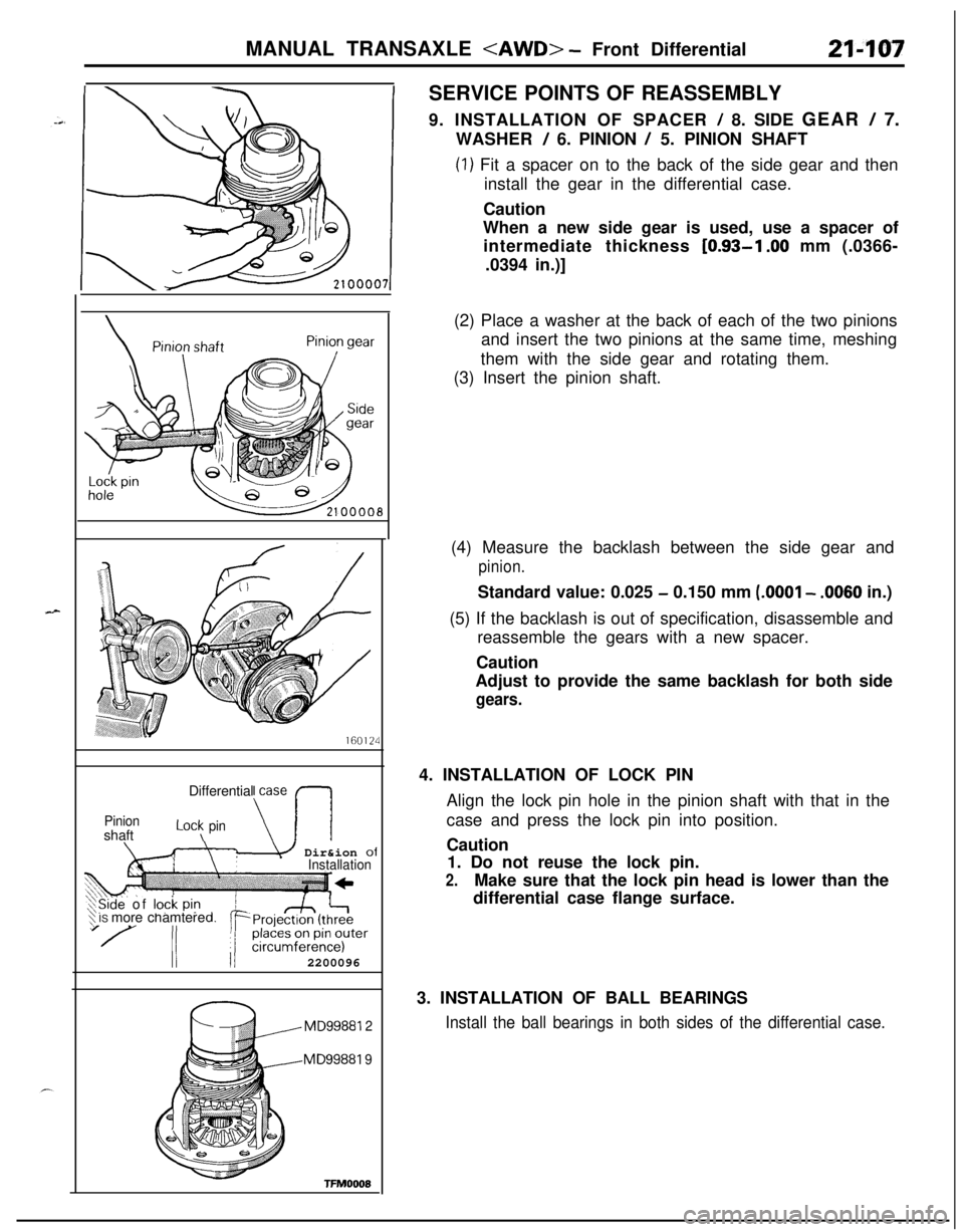
9. INSTALLATION OF SPACER
! 8. SIDE GEAR / 7.
WASHER
/ 6. PINION / 5. PINION SHAFT
(1) Fit a spacer on to the back of the side gear and then
install the gear in the differential case.
Caution
When a new side gear is used, use a spacer of
intermediate thickness
[0.93-l .OO mm (.0366-
.0394 in.)]
160124Differential case
PinionshaftLot\ pin\-I\m Dir&ion ofInstallation
‘$ IS more chamtereXSide of lock pi? d,
II II2200096
MD99881 2
MD99881 9
TFMOOOE(2) Place a washer at the back of each of the two pinions
and insert the two pinions at the same time, meshing
them with the side gear and rotating them.
(3) Insert the pinion shaft.
(4) Measure the backlash between the side gear and
pinion.Standard value: 0.025
- 0.150 mm (.OOOl - .0060 in.)
(5) If the backlash is out of specification, disassemble and
reassemble the gears with a new spacer.
Caution
Adjust to provide the same backlash for both side
gears.4. INSTALLATION OF LOCK PIN
Align the lock pin hole in the pinion shaft with that in the
case and press the lock pin into position.
Caution
1. Do not reuse the lock pin.
2.Make sure that the lock pin head is lower than the
differential case flange surface.
3. INSTALLATION OF BALL BEARINGS
Install the ball bearings in both sides of the differential case.
Page 802 of 1216
21-108MANUAL TRANSAXLE
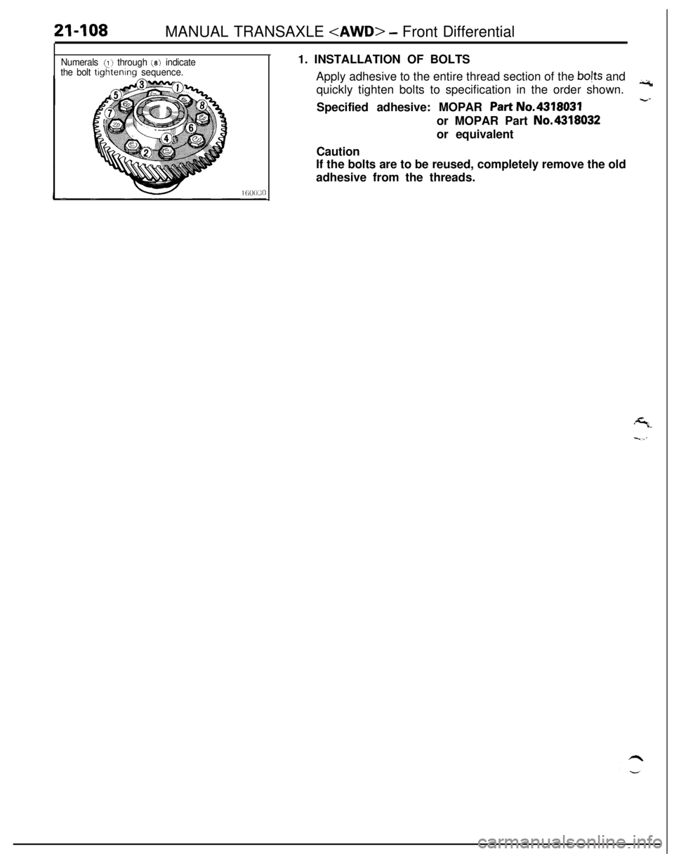
Numerals (I) through (8) indicate
the bolt tlghtenlng sequence.1. INSTALLATION OF BOLTS
Apply adhesive to the entire thread section of the bojts and
quickly tighten bolts to specification in the order shown.iii
-2Specified adhesive: MOPAR Part No.4318031
or MOPAR Part No.4318032
or equivalent
Caution
If the bolts are to be reused, completely remove the old
adhesive from the threads.
Page 832 of 1216
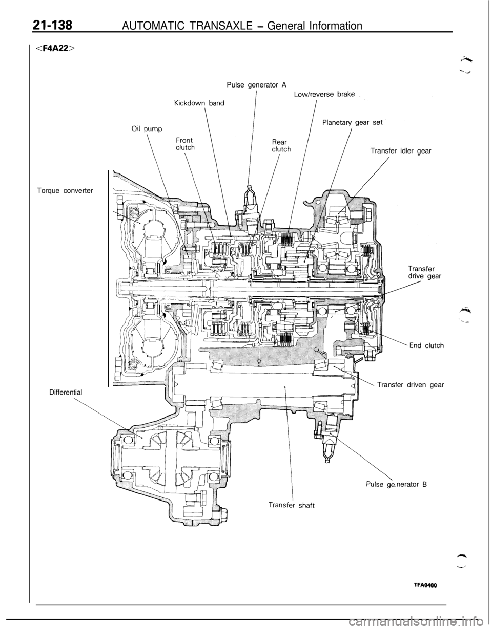
21-138AUTOMATIC TRANSAXLE - General Information
DifferentialPulse generator A
Transfer idler gear
Transfer driven gear
nerator
B
TFAO480
Page 833 of 1216
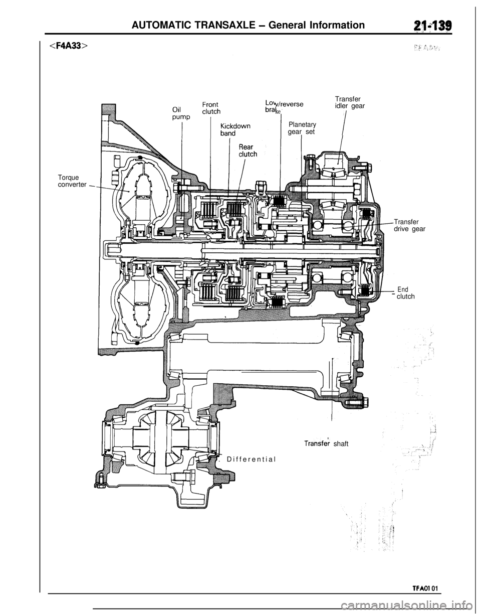
AUTOMATIC TRANSAXLE - General Information
Torqueconverter -werseTransfer
idler gear
Planetarygear set
!v/n
ke
Transferdrive gear
Transfek shaft
. Differential
End- clutch
TFAOl 01
Page 834 of 1216
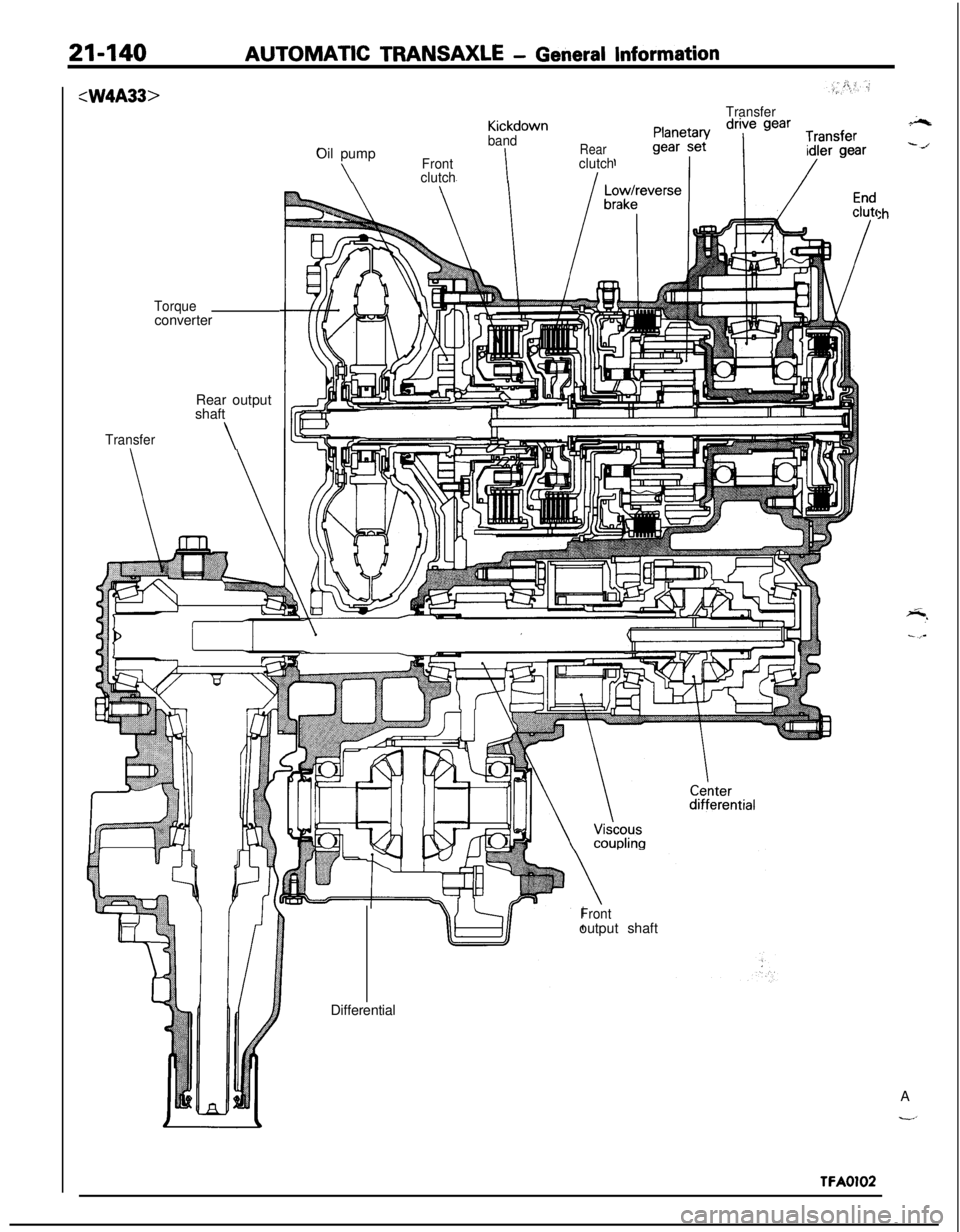
21-140AUTOMATIC TRANSAXLE - General Information:W4A33>
Torqueconverter
Rear output
shaft
Transfer\
TransferKickdown
bandOil pump
Rear
\FrontIclutch
clutchI
:h
Frontoutput shaft
2%
--/Differential
A
-’
TFA0102
Page 853 of 1216
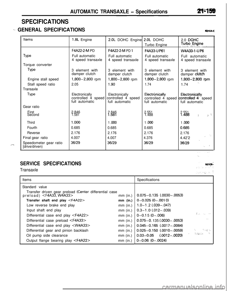
AUTOMATIC TRANSAXLE - Specifications
SPECIFICATIONS
-+ GENERAL [email protected]
TypeTorque converter
TypeEngine stall speed
Stall speed ratio
Transaxle
TypeGear ratio
First
Second
Third
Fourth
ReverseFinal ratio
gearSpeedometer gear ratio
[drive/driven)
1.8L Engine2.0L DOHC Engine 2.0L DOHC
2.0 DQHCTurbo Engine
T”‘pJyine.
F4A22-2-M PDF4A22-2-M PD 1F4A33-U P61W4A33-1 -U P6Full automatic
Full automatic
Full automatic
Full automatic
4 speed transaxle
4 speed transaxle4 speed transaxle
4 speed transaxle
3 element with
3 element with3 element with
3 element with
damper clutch
damper clutchdamper clutch
damper clfi&h
1,800-2,800 rpm1,800-2,800 rpm1,800-2,800 rpm1,800-2,806 ipm
2.051.901.741.74 *,
Electronically
Electronicallycontrolled 4 speed controlled 4 speedElectrbnicallyElectrotiicallyfull automaticcontrolled 4 speed controlled,i4’ speed
full automatic
full automatic
full automatic
2.846
2.8462.551
2.551c1.5811.5811.4881.488 f *r
1 .ooo
1 .ooo1 .ooo1 .ooo
0.685
0.6850.6850.685
2.176
2.1762.176
2.176
4.007
4.0074.3764.42’2
””
*36129361293612936129‘,!
SERVICE SPECIFICATIONS
TransaxleItems
Standard valueTransfer driven gear preload
(Center differential case
preload)
Transfer shaft end play
Low reverse brake end play
mm (in.)
Input shaft end play
mm (in.)
Differential case end play
Differential case preload
Differential case end play
Differential gear and pinion backlash
mm (in.)
Oil pump side clearance
mm (in.)
Output flange bearing play
0.075-0.135 (.0030-.0053)O-0.025
(O-.001 0)
1.0-l .2 (.039-,047)
0.3-l .o (.012-.039).,O-O.1 5 (O-.006),*, ,_ ,”0.075-O. 135
(.0030- .0053)1.
0.045-0.165 (.0017-.0064)
0.025-0.150 (.OOlO-.0059).,‘.a .;.; ‘>
o.03-o.05 (~oo12-~o(j~o’) ” i.u:-., ‘~O-0.06
(O-.0024)
Page 854 of 1216
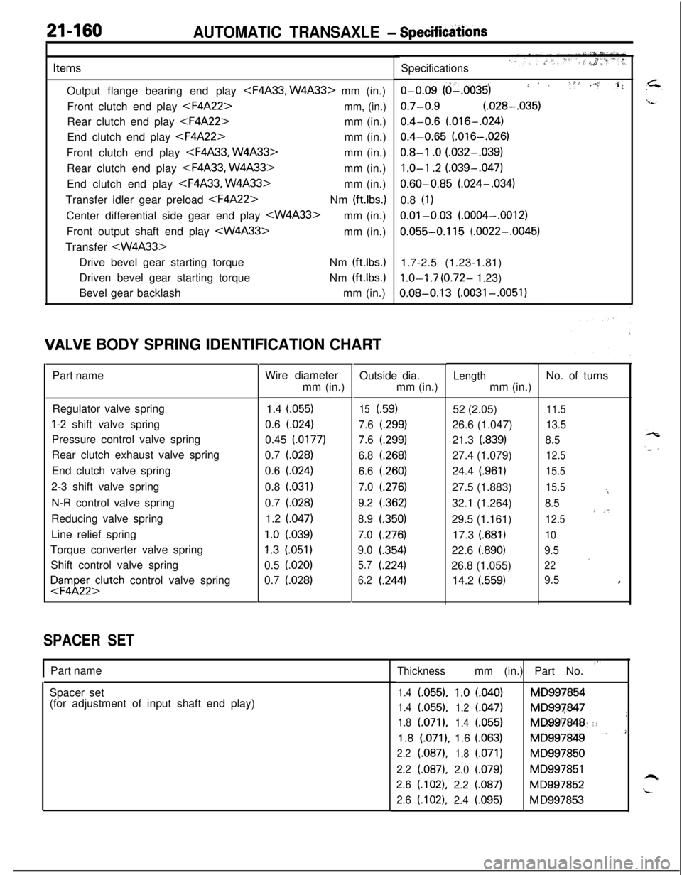
21-160AUTOMATIC TRANSAXLE - Specifidons
ItemsOutput flange bearing end play
Front clutch end play
End clutch end play
Front clutch end play
Rear clutch end play
End clutch end play
Transfer idler gear preload
Front output shaft end play
Transfer
Driven bevel gear starting torque
Bevel gear backlashNm
(ft.lbs.)Nm
(ft.lbs.)mm (in.)
IALVE BODY SPRING IDENTIFICATION CHARTPart name
Regulator valve spring
l-2 shift valve spring
Pressure control valve spring
Rear clutch exhaust valve spring
End clutch valve spring
2-3 shift valve spring
N-R control valve spring
Reducing valve spring
Line relief spring
Torque converter valve spring
Shift control valve spring
FFyl;;;lutch control valve spring
SPACER SETWire diameter
mm (in.)
1.4 (055)
0.6 (024)
0.45 (0177)
0.7 (028)
0.6
(.024)0.8
(.031)0.7 (028)
1.2 (047)
1.0 l.039)
1.3 (051)
0.5 (020)
0.7
(.028)Outside dia.
mm (in.)
15i.59)
7.6
t.299)
7.6(.299)
6.8(.268)
6.6(260)
7.0(276)
9.2(.362)
8.9(350)
7.0(276)
9.0(.354)
5.7(224)
6.2(.244)
IPart name
Spacer set
(for adjustment of input shaft end play)Specifications
o-0.09 (d-.0035); . ,i f 1, ,i’.” :,li
0.7-0.9 (.028-.035)
0.4-0.6 (.016-.024)
0.4-0.65 (.016-.026)
0.8-I .O (.032-.039)
1.0-I .2 (.039-.047)
0.60-0.85 (.024-.034)
0.8
(1)
0.01-0.03 (.0004-.0012)
0.055-0.115 (.0022-.0045)
1.7-2.5 (1.23-1.81)
1.0-I .7 (0.72- 1.23)
0.08-0.13 (.0031-.0051)
Lengthmm (in.)
52 (2.05)
26.6 (1.047)
21.3
(.839)27.4 (1.079)
24.4
(.961)27.5 (1.883)
32.1 (1.264)
29.5 (1.161)
17.3
(.681)22.6
i.890)26.8 (1.055)
14.2
(.559)No. of turns
11.5
13.5
8.5
12.5
15.5
15.5
‘4
8.5
’-*12.5
10
9.5
’22
9.5I
Thicknessmm (in.) Part No. “’
1.4(055).1.0l.040)MD997854
1.4(.055),
1.2(047)MD997847
’1.8(.071),
1.4l.055)MD997848::!1.8
(.071), 1.6 (.063)fQlD997849 ” .’
2.2(.087),
1.8(.071)MD997850
2.2(.087),2.0(.079)MD997851h2.6(.102),2.2(.087)MD997852“-2.6(.102),2.4i.095)M D997853
Page 855 of 1216
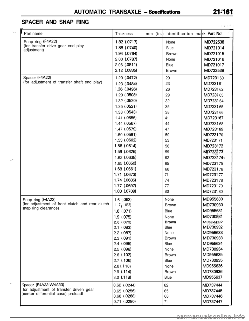
AUTOMATIC TRANSAXLE - SDecifications
SPACER AND SNAP RING
_ . ,_
_-Part name
Thicknessmm (in.) Identification mark Part We.’,1,Snap ring
(F4A22)1.82.(.0717)
NoneMD722538
(for transfer drive gear end play
adjustment)1.88 (.0740)BlueMD721014
1.94 (.0764)BrownMD721015
2.00 (0787)
NoneMD721016
2.06
(.081 I)BlueMD7210172.12
(.0835)BrownMD722538
Spacer
(F4A22)1.20 (0472)20MD7231 60(for adjustment of transfer shaft end play)
1.23 (0484)
23MD7231 61
1.26 (.0496)26MD7231 621.29 (0508)
29MD7231 631.32 (0520)
32MD7231 641.35 (0531)
35MD7231 651.38 (0543)
38MD7231 661.41 (0555)
41MD7231671.44
(.0567)44MD7231 681.47
(.0579)47MD723169
1.50
(.0591)
50MD7231 701.53 (0602)
53MD7231 71
1.56 (.0614)56MD723172
1.59 (0626)59Md@75,1.62
(.0638)
62MD723174~:1.65 (0650)
65MD7231 75
1.68 (.0661)68MD7231 76
1.71 (.0673)71MD7231 77
1.74 (.0685)74MD7231 78
1.77 (.0697)77MD7231 79
1.80 (.0709)80MD7231 80Snap ring
(F4A22)1.6 (.063)NoneMD955630[for adjustment of front clutch and rear clutch
snap ring clearance)1 . 7 ( . 067)BrownMD730930
1.8 (.071)BlueMP955631
1.9 l.075)None‘MD73Q93i2.0 f.079)BrownM~$G-$$?*
2.1
(.083)BlueM D7309322.2
(.087)NoneMD955633
2.3
(.091)BrownM D7309332.4
(.095)BlueM D9556342.5
i.098)NoneMD730934
2.6
(.102)BrownMD955635
2.7 (106)
BlueMD730935
2.8 (.I 10)
NoneMD9556362.9
(.114)BrownMD730936
3.0 (118)
BlueMD955637
Spacer (F4A33-W4A33)0.62 (.0244)62MD737444
for adjustment of transfer driven gear
icenter differential case) preloadl0.65 (0256)65MD7374450.68
(.0268)68MD737446
0.71 (0280)
71MD737447