torque MITSUBISHI ECLIPSE 1991 Owners Manual
[x] Cancel search | Manufacturer: MITSUBISHI, Model Year: 1991, Model line: ECLIPSE, Model: MITSUBISHI ECLIPSE 1991Pages: 1216, PDF Size: 67.42 MB
Page 656 of 1216
19-8STEERING - Service Adjustment Procedures < Manual Steering>
136005!Tape or mark
on steering
column cover
Tape or mark
on steering
wheel hub16A0901
Dotted lines
show wheel
Tape or mark
on steering
wheel rim
nce off-center
16AOOOl
IO036 splines
;EEE;D END BALL JOINT STARTING TORQUE
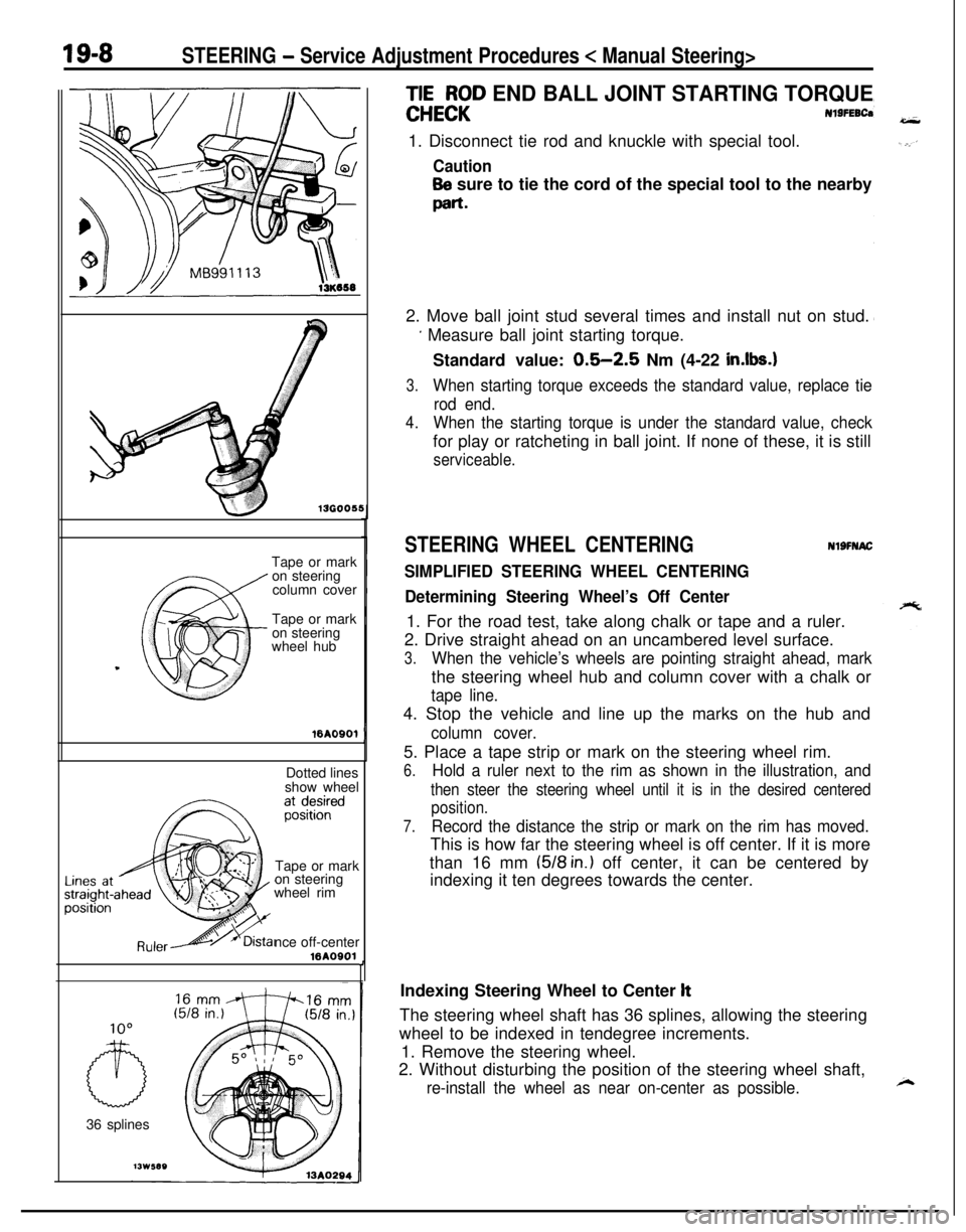
Nl9FEBCa1. Disconnect tie rod and knuckle with special tool.
Caution
Be sure to tie the cord of the special tool to the nearby
part-2. Move ball joint stud several times and install nut on stud.
’ Measure ball joint starting torque.
Standard value:
0.5-2.5 Nm (4-22 in.lbs.1
3.When starting torque exceeds the standard value, replace tie
rod end.
4.When the starting torque is under the standard value, checkfor play or ratcheting in ball joint. If none of these, it is still
serviceable.
STEERING WHEEL CENTERINGNlSFNAC
SIMPLIFIED STEERING WHEEL CENTERING
Determining Steering Wheel’s Off Center1. For the road test, take along chalk or tape and a ruler.
2. Drive straight ahead on an uncambered level surface.
3.When the vehicle’s wheels are pointing straight ahead, markthe steering wheel hub and column cover with a chalk or
tape line.4. Stop the vehicle and line up the marks on the hub and
column cover.5. Place a tape strip or mark on the steering wheel rim.
6.Hold a ruler next to the rim as shown in the illustration, and
then steer the steering wheel until it is in the desired centered
position.
7.Record the distance the strip or mark on the rim has moved.This is how far the steering wheel is off center. If it is more
than 16 mm
(518 in.) off center, it can be centered by
indexing it ten degrees towards the center.
,Indexing Steering Wheel to Center
ltThe steering wheel shaft has 36 splines, allowing the steering
wheel to be indexed in tendegree increments.
1. Remove the steering wheel.
2. Without disturbing the position of the steering wheel shaft,
re-install the wheel as near on-center as possible.
Page 657 of 1216
STEERING - Service Adjustment Procedures < Manual Steering>_ i ‘I 9;sSteering wheel off center left
13K71013A0289
Off center to leftOff center to left
Off center to rightOff center to right
Turn both tie rods in the same direction.
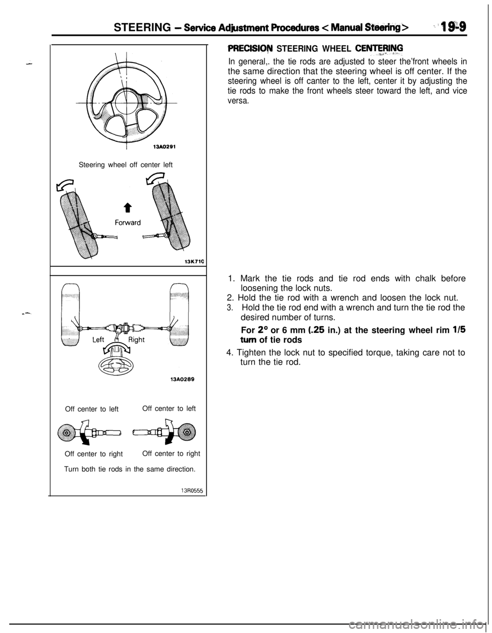
PRECISIG~ STEERING WHEEL CENTFFJIhll
In general,. the tie rods are adjusted to steer the’front wheels inthe same direction that the steering wheel is off center. If the
steering wheel is off canter to the left, center it by adjusting the
tie rods to make the front wheels steer toward the left, and vice
versa.1. Mark the tie rods and tie rod ends with chalk before
loosening the lock nuts.
2. Hold the tie rod with a wrench and loosen the lock nut.
3.Hold the tie rod end with a wrench and turn the tie rod the
desired number of turns.
For
2O or 6 mm (.25 in.) at the steering wheel rim 115
turn of tie rods
4. Tighten the lock nut to specified torque, taking care not to
turn the tie rod.
Page 658 of 1216
19-10STEERING - Service Adjustment Procedures c Power Steering>
r13A029213A0293
r
1
i
SERVICE ADJUSTMENT PROCEDURES
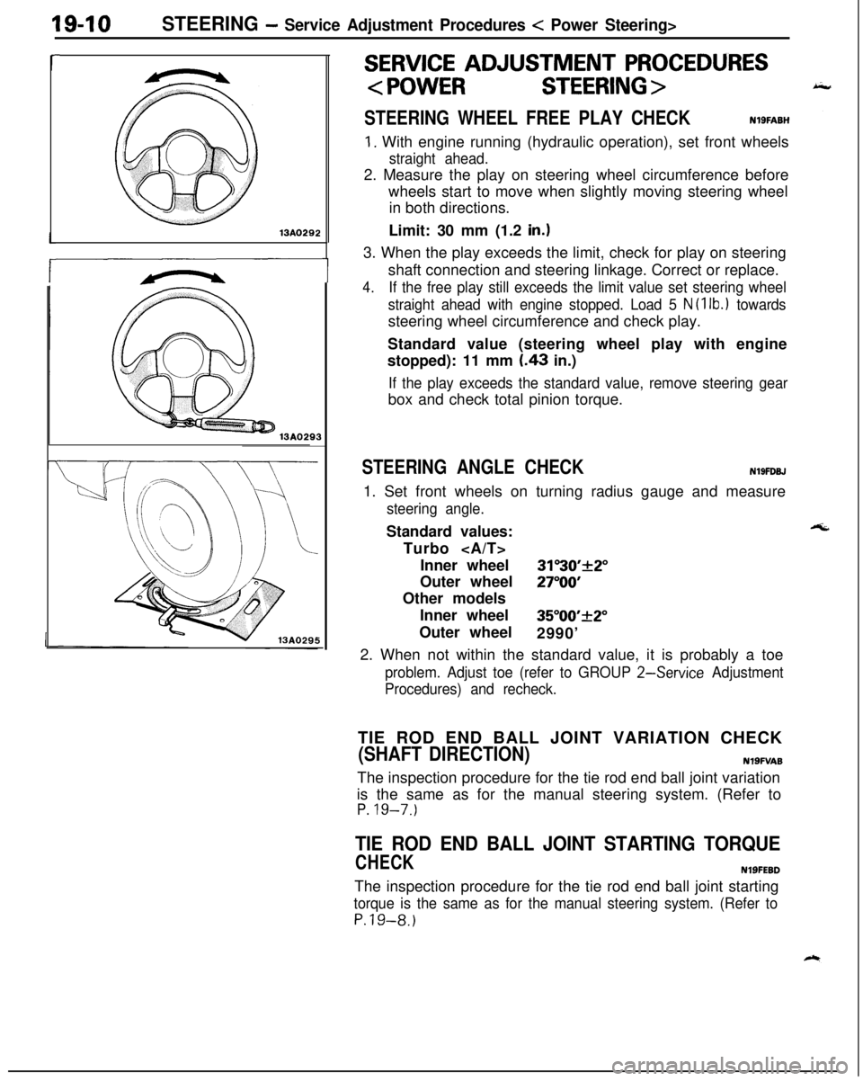
STEERING WHEEL FREE PLAY CHECKNlSFABH
1. With engine running (hydraulic operation), set front wheels
straight ahead.2. Measure the play on steering wheel circumference before
wheels start to move when slightly moving steering wheel
in both directions.
Limit: 30 mm (1.2
in.13. When the play exceeds the limit, check for play on steering
shaft connection and steering linkage. Correct or replace.
4.If the free play still exceeds the limit value set steering wheel
straight ahead with engine stopped. Load 5
N (1 lb.1 towardssteering wheel circumference and check play.
Standard value (steering wheel play with engine
stopped): 11 mm
I.43 in.)
If the play exceeds the standard value, remove steering gearbox and check total pinion torque.
STEERING ANGLE CHECKN19FDBJ1. Set front wheels on turning radius gauge and measure
steering angle.Standard values:
Turbo
Inner wheel
31”30’+2”Outer wheel
27”OOOther models
Inner wheel
35”00’_+2”Outer wheel
2990’
2. When not within the standard value, it is probably a toe
problem. Adjust toe (refer to GROUP 2-Service Adjustment
Procedures) and recheck.TIE ROD END BALL JOINT VARIATION CHECK
(SHAFT DIRECTION)N19FVA8The inspection procedure for the tie rod end ball joint variation
is the same as for the manual steering system. (Refer to
P. 19-7.)
TIE ROD END BALL JOINT STARTING TORQUE
CHECKNlSFEBDThe inspection procedure for the tie rod end ball joint starting
torque is the same as for the manual steering system. (Refer to
P.19-8.)
Page 662 of 1216
19-14STEERING - Service Adjustment Procedures < Power Steering >Shut-off valv
Pressure gauge
(FW close)
(C-3309-E)I
Temperature
gauge
\e’\
Pressure hoses
Re(Mti990994)
\Oil pump
713AO145Shut-off valve
Pressure gauge(FullY ?penl
Pressure hoses
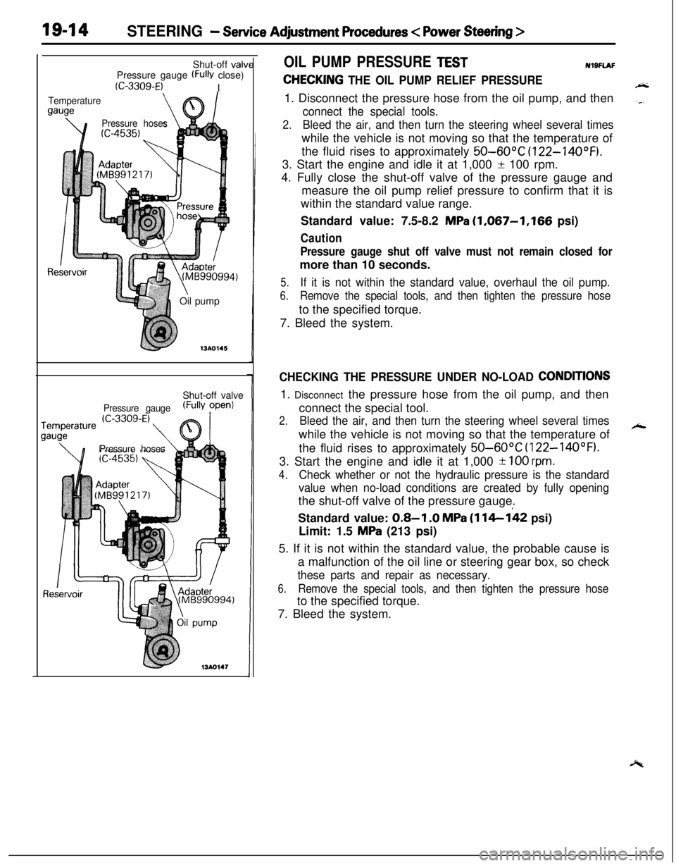
OIL PUMP PRESSURE TESTNl9FlAF
CHECKING THE OIL PUMP RELIEF PRESSURE1. Disconnect the pressure hose from the oil pump, and then
connect the special tools.
2.Bleed the air, and then turn the steering wheel several timeswhile the vehicle is not moving so that the temperature of
the fluid rises to approximately
50-60°C (122-14OOF).3. Start the engine and idle it at 1,000
f 100 rpm.
4. Fully close the shut-off valve of the pressure gauge and
measure the oil pump relief pressure to confirm that it is
within the standard value range.
Standard value: 7.5-8.2
MPa (1,067-1,166 psi)
Caution
Pressure gauge shut off valve must not remain closed formore than 10 seconds.
5.If it is not within the standard value, overhaul the oil pump.
6.Remove the special tools, and then tighten the pressure hoseto the specified torque.
7. Bleed the system.
CHECKING THE PRESSURE UNDER NO-LOAD CONDITIONS1. Disconnect the pressure hose from the oil pump, and then
connect the special tool.
2.Bleed the air, and then turn the steering wheel several timeswhile the vehicle is not moving so that the temperature of
the fluid rises to approximately
50-60°C (122-14OOF).3. Start the engine and idle it at 1,000
-t 100 rpm.
4.
Check whether or not the hydraulic pressure is the standard
value when no-load conditions are created by fully openingthe shut-off valve of the pressure gauge.
Standard value:
0.8-I .O MPa (114-142 psi)
Limit: 1.5
MPa (213 psi)
5. If it is not within the standard value, the probable cause is
a malfunction of the oil line or steering gear box, so check
these parts and repair as necessary.
6.Remove the special tools, and then tighten the pressure hoseto the specified torque.
7. Bleed the system.
Page 663 of 1216
-
c. .
STEERING - Service Adiustment Procedures
Shut-off valve
Pressure gauge
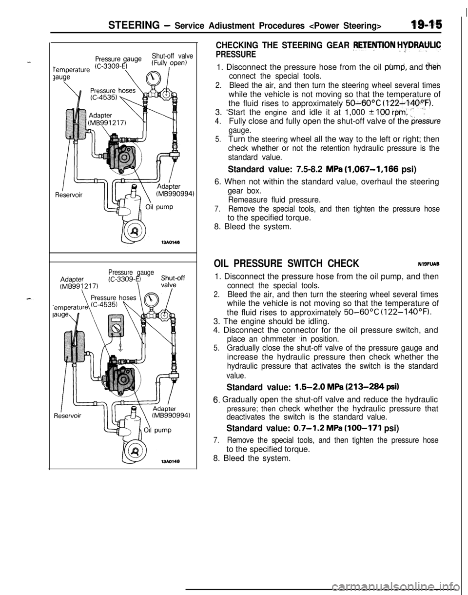
CHECKING THE STEERING GEAR PETENTION HYDRAULIC
PRESSURE1. Disconnect the pressure hose from the oil
pbmd, and iheh
connect the special tools.
2.Bleed the air, and then turn the steering wheel several timeswhile the vehicle is not moving so that the temperature of
the fluid rises to approximately
50~60OC (122~14pyF).
3. ‘Start the engine and idle it at 1,000 +
100 rem: .‘,’.
4.Fully close and fully open the shut-off valve of the pressure
gauge.
5.Turn the steering wheel all the way to the left or right; then
check whether or not the retention hydraulic pressure is the
standard value.
Standard value: 7.5-8.2 MPa (1,067-1,166 psi)6. When not within the standard value, overhaul the steering
gear box.
Remeasure fluid pressure.
7.Remove the special tools, and then tighten the pressure hoseto the specified torque.
8. Bleed the system.
OIL PRESSURE SWITCH CHECKNlSFUAB1. Disconnect the pressure hose from the oil pump, and then
connect the special tools.
2.Bleed the air, and then turn the steering wheel several timeswhile the vehicle is not moving so that the temperature of
the fluid rises to approximately
50-60°C (122-14OOF).3. The engine should be idling.
4. Disconnect the connector for the oil pressure switch, and
place an ohmmeter ,in position.
5.Gradually close the shut-off valve of the pressure gauge andincrease the hydraulic pressure then check whether the
hydraulic pressure that activates the switch is the standard
value.
Standard value: 1.5-2.0 MPa (213-284 psi)
6. Gradually open the shut-off valve and reduce the hydraulic
pressure; then check whether the hydraulic pressure that
deactivates the switch is the standard value.
Standard value: 0.7-1.2 MPa (100-171 psi)
7.Remove the special tools, and then tighten the pressure hoseto the specified torque.
8. Bleed the system.
Page 670 of 1216
19-22STEERING - Manual Steering Gear Box
13Roo7!
J Mow&g clamp
SERVICE POINTS OF REMOVAL.dlSLl$iF
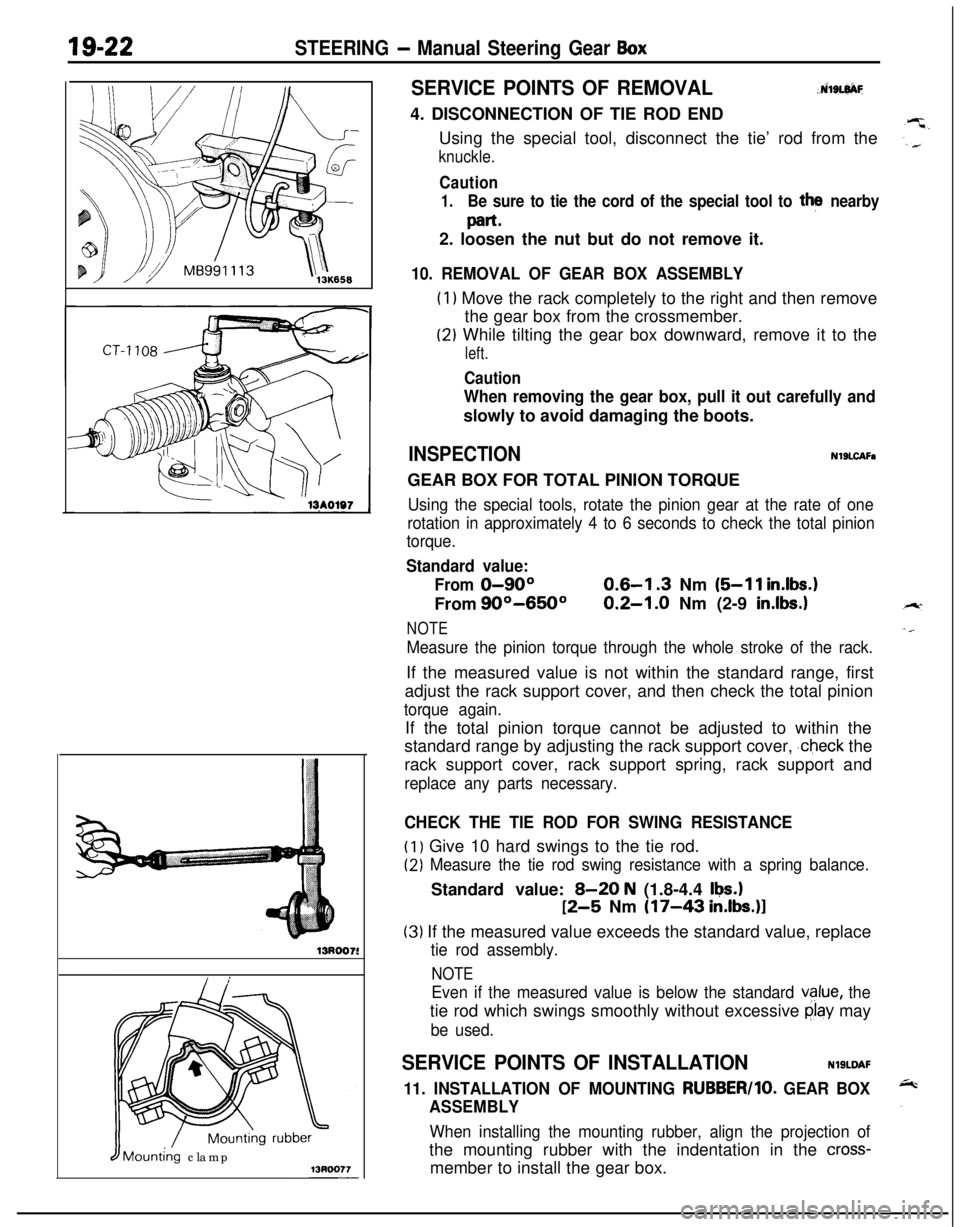
4. DISCONNECTION OF TIE ROD END
Using the special tool, disconnect the tie’ rod from the
knuckle.
Caution
1.Be sure to tie the cord of the special tool to the nearby
part*2. loosen the nut but do not remove it.
10. REMOVAL OF GEAR BOX ASSEMBLY
(1) Move the rack completely to the right and then remove
the gear box from the crossmember.
(2) While tilting the gear box downward, remove it to the
left.
Caution
When removing the gear box, pull it out carefully andslowly to avoid damaging the boots.
INSPECTIONNlSLCAFaGEAR BOX FOR TOTAL PINION TORQUE
Using the special tools, rotate the pinion gear at the rate of one
rotation in approximately 4 to 6 seconds to check the total pinion
torque.
Standard value:
From
0-90°0.6-l .3 Nm (5-11 in.lbs.1From
90°-650°0.2-1.0 Nm (2-9 in.lbs.1
NOTE
Measure the pinion torque through the whole stroke of the rack.If the measured value is not within the standard range, first
adjust the rack support cover, and then check the total pinion
torque again.If the total pinion torque cannot be adjusted to within the
standard range by adjusting the rack support cover,
,check the
rack support cover, rack support spring, rack support and
replace any parts necessary.
CHECK THE TIE ROD FOR SWING RESISTANCE
(1) Give 10 hard swings to the tie rod.
(2) Measure the tie rod swing resistance with a spring balance.Standard value:
B-20 N (1.8-4.4 Ikw.1
12-5 Nm (17-43 in.lbs.)l
(3) If the measured value exceeds the standard value, replace
tie rod assembly.
NOTE
Even if the measured value is below the standard vglue, thetie rod which swings smoothly without excessive
clay may
be used.
SERVICE POINTS OF INSTALLATIONNlSLDAF
11. INSTALLATION OF MOUNTING RUBBER/lo. GEAR BOX
ASSEMBLY
When installing the mounting rubber, align the projection ofthe mounting rubber with the indentation in the
cross-member to install the gear box.
Page 671 of 1216
STEERING - Manual Steering Gear Box
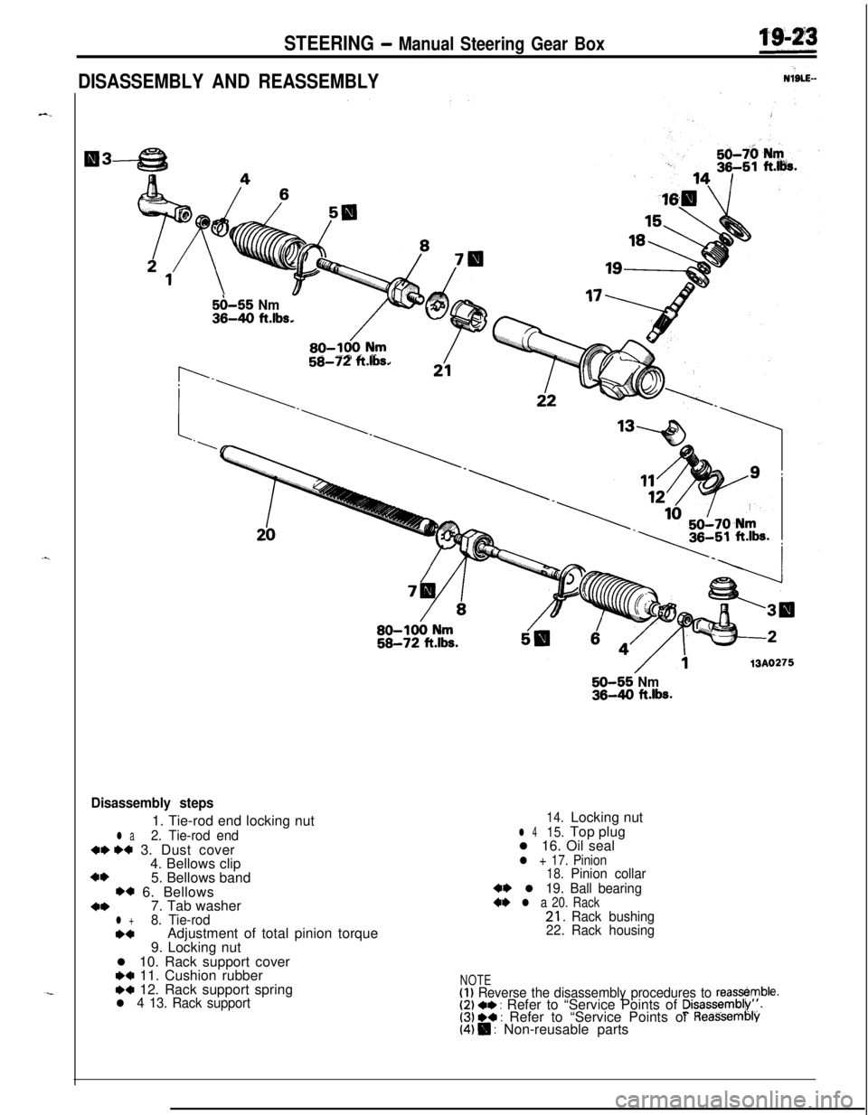
DISASSEMBLY AND REASSEMBLY
5i)-55 Nm36-40 ft.lbs.
58-72 ft.lbs.
50-55 Nm36-40 ft.lbs.
13A0275
Disassembly steps1. Tie-rod end locking nut
l a2. Tie-rod end
W M 3. Dust cover
4. Bellows clip
+I)5. Bellows band
w 6. Bellows
+*7. Tab washerl +8. Tie-rod*aAdjustment of total pinion torque
9. Locking nut
l 10. Rack support cover
H 11. Cushion rubberw 12. Rack support springl 4 13. Rack support
14.Locking nut
l 415.Top plug
l 16. Oil seal
l + 17. Pinion
18.Pinion collar
4~ l 19. Ball bearing+* l a 20. Rack21.Rack bushing
22.Rack housing
NOTE(1) Reverse the disassembly procedures to reass&mble.(2) +e : Refer to “Service Points of Disassemblk’,‘.(3) ** : Refer to “Service Points of Reas’sembly(4) $I : Non-reusable parts
Page 674 of 1216
19-26STEERING - Manual Steering Gear Box
Grease
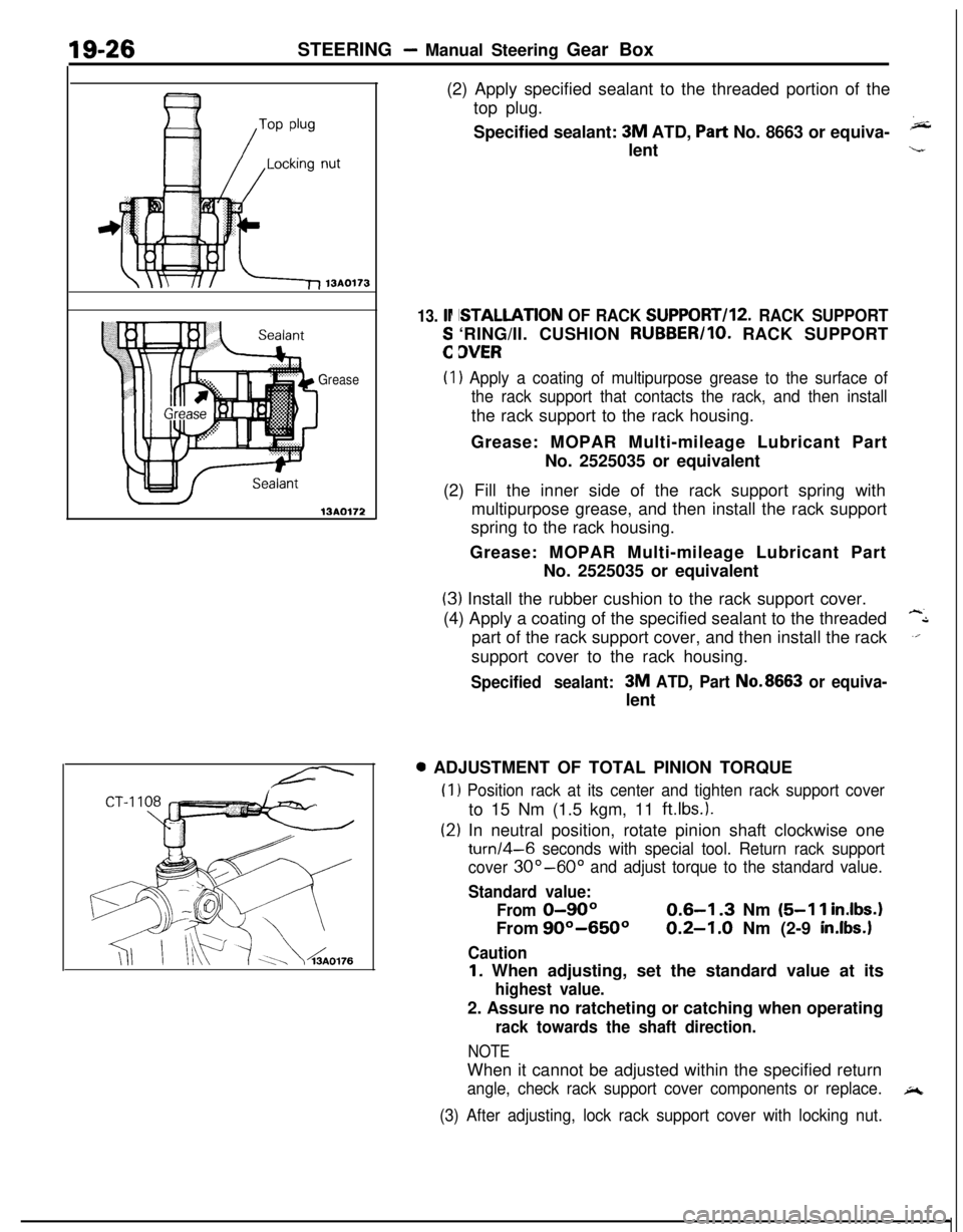
13AO172(2) Apply specified sealant to the threaded portion of the
top plug.
Specified sealant:
3M ATD, Part No. 8663 or equiva-klent
13. lr
:
ISTALLATION OF RACK SUPPORT/l2. RACK SUPPORT‘RING/II. CUSHION RUBBER/IO. RACK SUPPORT
3VER
(I) Apply a coating of multipurpose grease to the surface of
the rack support that contacts the rack, and then installthe rack support to the rack housing.
Grease: MOPAR Multi-mileage Lubricant Part
No. 2525035 or equivalent
(2) Fill the inner side of the rack support spring with
multipurpose grease, and then install the rack support
spring to the rack housing.
Grease: MOPAR Multi-mileage Lubricant Part
No. 2525035 or equivalent
(3) Install the rubber cushion to the rack support cover.
(4) Apply a coating of the specified sealant to the threaded
-Lpart of the rack support cover, and then install the rack
.‘.support cover to the rack housing.
Specified sealant:3M ATD, Part No.8663 or equiva-lent0 ADJUSTMENT OF TOTAL PINION TORQUE
(1
(2
) Position rack at its center and tighten rack support coverto 15 Nm (1.5 kgm, 11
ftlbs.).
:) In neutral position, rotate pinion shaft clockwise one
turn/4-6 seconds with special tool. Return rack support
cover
30”-60” and adjust torque to the standard value.
Standard value:
From
0-90°From
90°-650°
Caution
0.6-I .3 Nm (5-l 1 inIbs.
0.2-1.0 Nm (2-9 in.lbs.1
I. When adjusting, set the standard value at its
highest value.2. Assure no ratcheting or catching when operating
rack towards the shaft direction.
NOTEWhen it cannot be adjusted within the specified return
angle, check rack support cover components or replace.A
(3) After adjusting, lock rack support cover with locking nut.
Page 677 of 1216
STEERING - Power Steering Gear Box
lS1017S
I /Mounting rubber
IIMdting clamp13Roo77
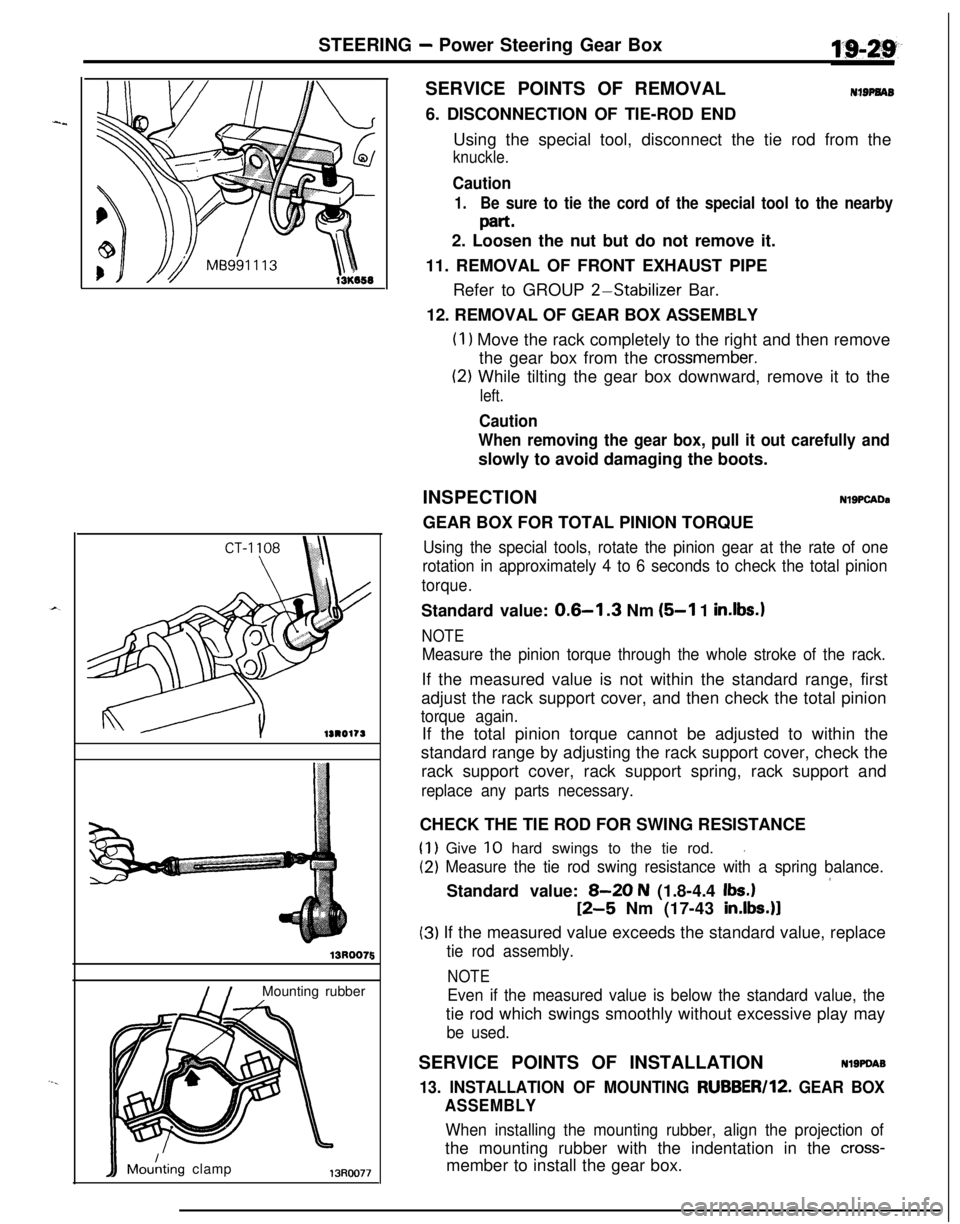
5SERVICE POINTS OF REMOVAL
NIBPNAB6. DISCONNECTION OF TIE-ROD END
Using the special tool, disconnect the tie rod from the
knuckle.
Caution
1.Be sure to tie the cord of the special tool to the nearby
part.2. Loosen the nut but do not remove it.
11. REMOVAL OF FRONT EXHAUST PIPE
Refer to GROUP
2-Stabilizer Bar.
12. REMOVAL OF GEAR BOX ASSEMBLY
(I 1 Move the rack completely to the right and then remove
the gear box from the
crossmember.
(2) While tilting the gear box downward, remove it to the
left.
Caution
When removing the gear box, pull it out carefully andslowly to avoid damaging the boots.
INSPECTION
NlSPCADaGEAR BOX FOR TOTAL PINION TORQUE
Using the special tools, rotate the pinion gear at the rate of one
rotation in approximately 4 to 6 seconds to check the total pinion
torque.Standard value:
0.6-l .3 Nm (5-l 1 in.lbs.1
NOTE
Measure the pinion torque through the whole stroke of the rack.If the measured value is not within the standard range, first
adjust the rack support cover, and then check the total pinion
torque again.If the total pinion torque cannot be adjusted to within the
standard range by adjusting the rack support cover, check the
rack support cover, rack support spring, rack support and
replace any parts necessary.CHECK THE TIE ROD FOR SWING RESISTANCE
(1) Give 10 hard swings to the tie rod.I
(2) Measure the tie rod swing resistance with a spring balance.
’Standard value: 8-20 N (1.8-4.4 Ibs.)
12-5 Nm (17-43 in.lbs.)l
(3) If the measured value exceeds the standard value, replace
tie rod assembly.
NOTE
Even if the measured value is below the standard value, thetie rod which swings smoothly without excessive play may
be used.SERVICE POINTS OF INSTALLATION
Nl9PDA9
13. INSTALLATION OF MOUNTING RUBBER/lZ. GEAR BOX
ASSEMBLY
When installing the mounting rubber, align the projection ofthe mounting rubber with the indentation in the
cross-member to install the gear box.
Page 678 of 1216
19-30STEERING - Power Steering Gear Box
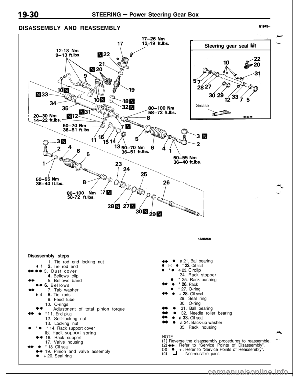
DISASSEMBLY AND REASSEMBLY
12-18
Nm9-13 ftlbs.
17-28 Nm17 ,-12 19 ft.lbs.rSteering gear seal k!t
Grease
23;>.
50155 Nm36-40 ft.lbs.I
I2b
I‘\SO-56 Nm36-40 ft.lbs.
80-100 Nm : _58-72 ft.lbs./ /
Disassembly steps1. Tie rod end locking nut
l 42. Tie rod end+I) I)+ 3. Dust cover
4. Bellows clip
a*5. Bellows band
*a 6. Bellows4,7. Tab washer
l 48. Tie rods
9. Feed tube
10. O-rings
*aAdjustment of total pinion torque
+* l * II. End plug12. Self-locking nut
13. Locking nut
l * l * 14. Rack support cover
_- -lb. Hack SUppOrt sprlngw 16. Rack support
17. Valve housing
+* l * 18. Oil seal,+ 19. Pinion and valve assembly
l + 20. Seal ringmo25a
+e l a 21. Ball bearingl * l * 22. Oil seall * l 4 23. Circlip
24. Rack stopper
l * 25. Rack bushing
4* l * 26. Rackl * 27. O-ring
+* l + 28. Oil seal29. Seal ring
30. O-ring
++ l 31. Ball bearing+W l 32. Needle roller bearing+* l a 33. Oil seal+* l a 34. Back-up washer
35. Rack housing
NOTE(1) Reverse the disassembly procedures to reassemble.(2) +e : Refer to “Service Points of Disassembly”.(3) l + : Refer to “Service Points of Reassembly”.(4) q : Non-reusable parts