torque MITSUBISHI ECLIPSE 1991 Service Manual
[x] Cancel search | Manufacturer: MITSUBISHI, Model Year: 1991, Model line: ECLIPSE, Model: MITSUBISHI ECLIPSE 1991Pages: 1216, PDF Size: 67.42 MB
Page 1198 of 1216

EMISSION CONTROL SYSTEMS - Specifications
SPECIFICATIONS
GENERAL SPECIFICATIONSN25CA-ItemsSpecifications
.,:..rCrankcase emission control systemClosed type with positive crankcase ventilation valve”I
‘:Evaporative emission control systemCanister storage type
CanisterCharcoal type
Exhaust emission control system
Exhaust gas recirculation system
EGR valveVacuum-activated diaphragm type
Therm0 valveBimetal type
EGR temperature sensor
EGR control solenoid valve
Duty cycle solenoid valve
Catalytic converterMonolith type
LocationUnder floor
SERVICE SPECIFICATIONSN25CB-
ItemsSpecifications
Purge-control solenoid valve coil resistance
&236-44 [at 20°C (68”F)I
Therm0 valve closing temperature“C (“F)65 (149)
EGR temperature sensor resistance
kQ60-83 [at 50°C (122”F)]11-14 [at
100°C (212”F)]EGR control solenoid valve coil resistance
S236-44 [at 20°C (68”F)]
TORQUE SPECIFICATIONSN25CC-
ItemsPositive crankcase ventilation valve
EGR valve installation bolt
<2.0L DOHC Engine>
Therm0 valve
EGR temperature sensor
Nmftlbs.8-12
6-8.5
IO-157.2-1015-22
10-15.5
20-4015-30
10-127.3-8.6
SEALANT
Items
Therm0 valve thread portionSpecified sealant
MOPAR Part No.4318034 or equivalent
Page 1204 of 1216

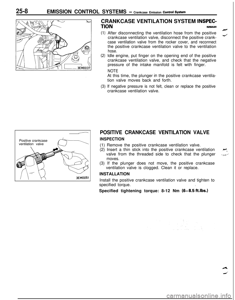
25-8EMISSION CONTROL SYSTEMS - Crankcase Emission Control System
-Positive crankcase
ventilation valve3EM0051CRANKCASE VENTILATION SYSTEM
INSPEC-
TIONNZSIAAHAfter disconnecting the ventilation hose from the positive
crankcase ventilation valve, disconnect the positive crank-
case ventilation valve from the rocker cover, and reconnectthe positive crankcase ventilation valve to the ventilation
hose.
Idle engine, put finger on the opening end of the positive
crankcase ventilation valve, and check that the negative
pressure of the intake manifold is felt with finger.
NOTEAt this time, the plunger
Ian the positive crankcase ventila-
tion valve moves back and forth.
(3) If negative pressure is not felt, clean or replace the positivecrankcase ventilation valve.
POSITIVE CRANKCASE VENTILATION VALVE
INSPECTION(1) Remove the positive crankcase ventilation valve.
(2) Insert a thin stick into the positive crankcase ventilation
valve from the threaded side to check that the plunger
moves.(3) If the plunger does not move, the positive crankcase
ventilation valve is clogged. Clean it or replace.
INSTALLATION
Install the positive crankcase ventilation valve and tighten to
specified torque.
iSpecified tightening torque: 8-12 Nm
(8-8.5 ft.lbs.)
Page 1214 of 1216

25-18EMISSION CONTROL SYSTEMS- Exhaust Gas Recirculation (EGRI System
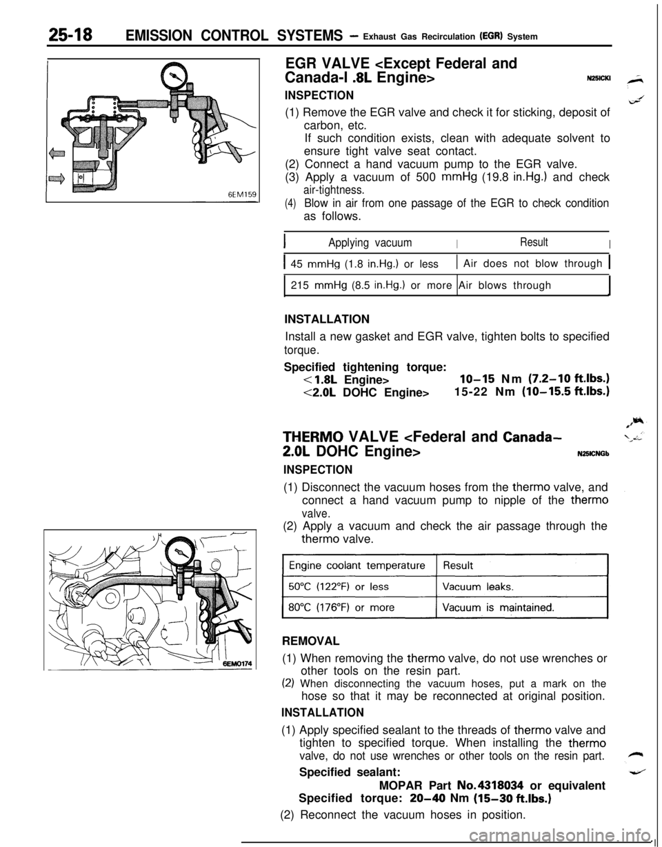
EGR VALVE
INSPECTION(1) Remove the EGR valve and check it for sticking, deposit of
carbon, etc.
If such condition exists, clean with adequate solvent to
ensure tight valve seat contact.
(2) Connect a hand vacuum pump to the EGR valve.
(3) Apply a vacuum of 500 mmHg (19.8
in.Hg.) and check
air-tightness.
(4)Blow in air from one passage of the EGR to check conditionas follows.
IApplying vacuumIResultI
I45 mmHg (1.8 in.Hg.1 or less1 Air does not blow through 1215
mmHg (8.5 in.Hg.1 or more Air blows through
INSTALLATION
Install a new gasket and EGR valve, tighten bolts to specified
torque.Specified tightening torque:
< 1.8L Engine>lo-15 Nm (7.2-10 ft.lbs.)
<2.0L DOHC Engine>15-22 Nm (lo-155 ft.lbs.)
THERM0 VALVE
INSPECTION(1) Disconnect the vacuum hoses from the therm0 valve, and
connect a hand vacuum pump to nipple of the therm0
valve.(2) Apply a vacuum and check the air passage through thetherm0 valve.
REMOVAL
(1) When removing the therm0 valve, do not use wrenches or
other tools on the resin part.
(2) When disconnecting the vacuum hoses, put a mark on the
hose so that it may be reconnected at original position.
INSTALLATION(1) Apply specified sealant to the threads of therm0 valve and
tighten to specified torque. When installing the therm0
valve, do not use wrenches or other tools on the resin part.Specified sealant:
MOPAR Part No.4318034 or equivalent
Specified torque:
20-40 Nm (15-30 ftlbs.)(2) Reconnect the vacuum hoses in position.
‘I
Page 1215 of 1216

EMISSION CONTROL SYSTEMS- Exhaust Gas Recirculation (EGR) Svstem25-19
\\
7EM0043
. .
6EM0187
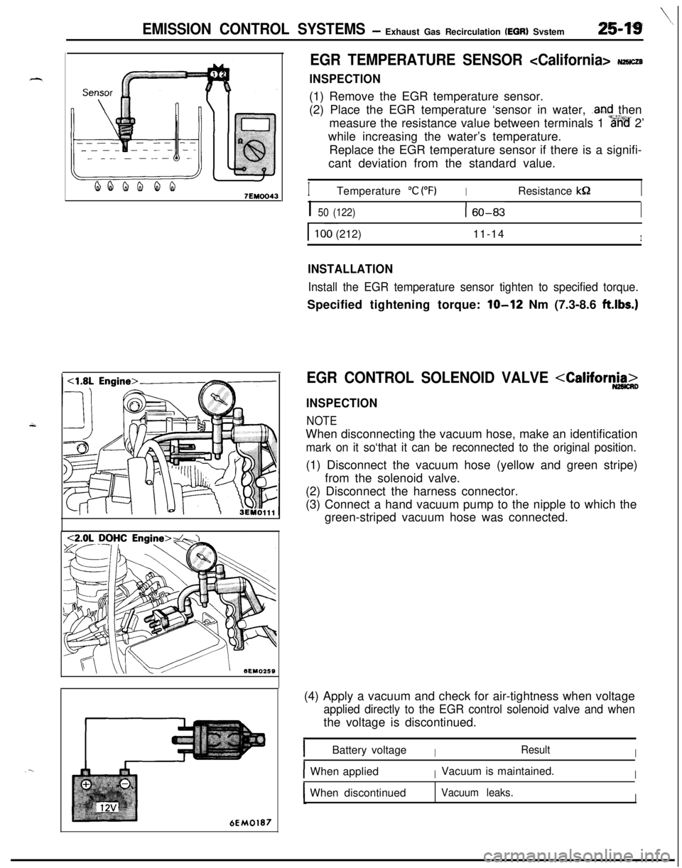
EGR TEMPERATURE SENSOR
INSPECTION(1) Remove the EGR temperature sensor.
(2) Place the EGR temperature ‘sensor in water,
.and then
measure the resistance value between terminals 1
%%’ 2’
while increasing the water’s temperature.
Replace the EGR temperature sensor if there is a signifi-
cant deviation from the standard value.
ITemperature “C (“F)IResistance kS2I
I 50 (122)160-83I
I ~~100 (212)11-14I
INSTALLATION
Install the EGR temperature sensor tighten to specified torque.Specified tightening torque:
lo-12 Nm (7.3-8.6 ft.lbs.)
EGR CONTROL SOLENOID VALVE
NOTEWhen disconnecting the vacuum hose, make an identification
mark on it so‘that it can be reconnected to the original position.(1) Disconnect the vacuum hose (yellow and green stripe)
from the solenoid valve.
(2) Disconnect the harness connector.
(3) Connect a hand vacuum pump to the nipple to which the
green-striped vacuum hose was connected.
(4) Apply a vacuum and check for air-tightness when voltage
applied directly to the EGR control solenoid valve and whenthe voltage is discontinued.
IBattery voltageIResultI
IWhen appliedIVacuum is maintained.IWhen discontinued
Vacuum leaks.I