torque MITSUBISHI ECLIPSE 1991 Service Manual
[x] Cancel search | Manufacturer: MITSUBISHI, Model Year: 1991, Model line: ECLIPSE, Model: MITSUBISHI ECLIPSE 1991Pages: 1216, PDF Size: 67.42 MB
Page 685 of 1216
STEERING - Power Steering Gear Box
13A017EI
\Silicon grease
Lip
Sealant131564-r-MB990776-A
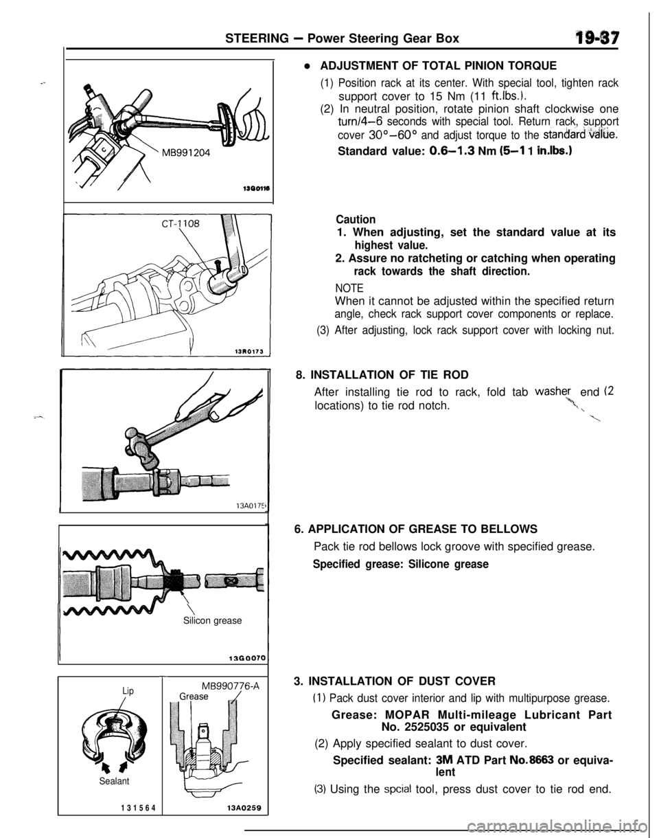
13A0259l ADJUSTMENT OF TOTAL PINION TORQUE
(1) Position rack at its center. With special tool, tighten racksupport cover to 15 Nm (11
ftlbs.).(2) In neutral position, rotate pinion shaft clockwise one
turn/4-6 seconds with special tool. Return rack, support
cover
30°-60° and adjust torque to the stanoard,vaiue.Standard value:
0.6-l .3 Nm (5-l 1 in.lbs.1
Caution1. When adjusting, set the standard value at its
highest value.2. Assure no ratcheting or catching when operating
rack towards the shaft direction.
NOTEWhen it cannot be adjusted within the specified return
angle, check rack support cover components or replace.
(3) After adjusting, lock rack support cover with locking nut.8. INSTALLATION OF TIE ROD
After installing tie rod to rack, fold tab washe;, end (2
locations) to tie rod notch.
‘*,t, \
\6. APPLICATION OF GREASE TO BELLOWS
Pack tie rod bellows lock groove with specified grease.
Specified grease: Silicone grease3. INSTALLATION OF DUST COVER
(1) Pack dust cover interior and lip with multipurpose grease.Grease: MOPAR Multi-mileage Lubricant Part
No. 2525035 or equivalent
(2) Apply specified sealant to dust cover.
Specified sealant: 3M ATD Part
No.8663 or equiva-
lent
(3) Using the spcial tool, press dust cover to tie rod end.
Page 695 of 1216
TRANSAXLE ’
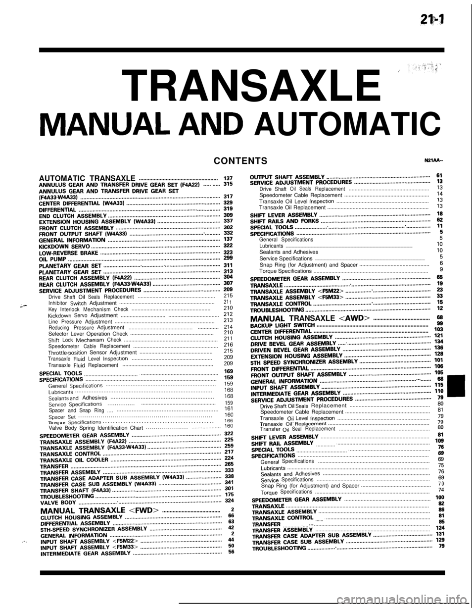
MANUAL AND AUTOMATICCONTENTS
;-AUTOMATICTRANSAXLE
.....................................................137ANNULUS GEAR AND TRANSFER DRIVE GEAR SET (F4A22)..........315ANNULUS GEAR AND TRANSFER DRIVE GEAR SET(F4A33.W4A33)...........................................................................................317CENTERDIFFERENTIAL(W4A33).............................................................329DIFFERENTIAL............................................................................................319ENDCLUTCHASSEMBLY.........................................................................309EXTENSIONHOUSINGASSEMBLY(W4A33).........................................337FRONTCLUTCHASSEMBLY....................................................................302FRONTOUTPUTSHAFT(W4A33)...........................................................332GENERALINFORMATION.........................................................................137KICKDOWNSERVO....................................................................................322LOW-REVERSEBRAKE..............................................................................323OILPUMP...................................................................................................299PLANETARYGEARSET............................................................................311PLANETARYGEARSET............................................................................313REARCLUTCHASSEMBLY(F4A22)........................................................304REARCLUTCHASSEMBLY(FQA33sW4A33)............................................307SERVICEADJUSTMENTPROCEDURES..................................................Drive
Shaft,OilSealsReplacement....................................................;;;
InhibitorSwtchAdjustment................................................................21 1KeyInterlockMechanismCheck.....................................................KrckdownServoAdjustment..................................zii..............................
LinePressureAdjustment...................................................................213
ReducingPressureAdjustment.........................................................214Selector Lever Operation Check........................................................210ShiftLockMechanismCheck...............................................................21 1SpeedometerCableReplacement.........................................................Throttle-posltipn Sensor Adjustment.................................................z2:
TransaxleFluIdLevelInspectIon......................................................209
TransaxleFluidReplacement.............................................................209
SPECIALTOOLS.........................................................................................SPECIFICATIONS........................................................................................;“5”9
GeneralSpeclficatlons..................................................................1%Lubricants..................................................................................Sealants and Adhesives..............................................................izi
Serwce Speclflcatlons..................................................159...............Spacer andSnapRing.,.,.............................................................Spacer Set..................................................................1::Torque Speclflcatlons...........................................166Valve Body Spring Identification Chart.....................
.................160
SPEEDOMETERGEARASSEMBLY..........................................................TRANSAXLEASSEMBLY(WA22)............................................................zTRANSAXLE
ASSEMBLY(F4A33.W4A33)................................................TRANSAXLECONTROL.............................................................................;;;TRANSAXLE
OILCOOLER........................................................................TRANSFER..................................................................................................fg
TRANSFERASSEMBLY.............................................................................333TRANSFERCASEADAPTERSUBASSEMBLY(W4A33).......................339TRANSFER CASE SUB ASSEMBLY (W4A33)341TRANSFER SHAFT (F4A33)TROUBLESHOOTING..................................................................................................................................................................................................f;;VALVE
BODY.............................................................................................324
MANUAL TRANSAXLE
5TH-SPEEDSYNCHRONIZERASSEMBLY...............................................42GENERALINFORMATION.........................................................................2.-.INPUTfj,-,A,TASSEMBLY
INTERMEDIATE GEAR ASSEMBLY..........................................................56OUTPUT
SHAFT ASSEMBLY....................................................................61SERVICEADJUSTMENTPROCEDURES..................................................DriveShaftOilSealsReplacement......................................................;;Speedometer Cable Replacement.........................................................
Transaxle Oil Level
InspectIon..............................................................‘liTransaxle Oil Replacement....................................................................
I3
SHIFTLEVERASSEMBLY.........................................................................SHIFTRAILSANDFORKS........................................................................g
SPECIALTOOLS.........................................................................................SPECIFICATIONS........................................................................................1:
General Specifications5Lubricants..........................................................................................................................................................................10Sealants and Adhesives
Service Specifications
....................................................................................................................................................1:Snap Ring (for Adjustment) and Spacer...............................................
Torque Specifications.............................................................................
i
SPEEDOMETERGEARASSEMBLY..........................................................TRANS&G.E................................................................................................zTRANSAXLEA!jSEMBLY
TROUBLESHOOTING..................................................................................12
MANUAL TRANSAXLE
CENTERDIFFERENTIAL.............................................................................103CLUTCHHOUSINGASSEMBLY...............................................................DRIVE BEVEL GEAR ASSEMBLY;g
...... .......................................................DRIVENBEVELGEARASSEMBLY...................................a......................EXTENSIONHOUSINGASSEMBLY.........................................................;g
5Tf.jSPEEDSYNCHRONIZERASSEMBLY...............................................101
FRONTDlFFERENTlAL...............................................................................106
FRONTOUTPUTSHAFTASSEMBLY......................................................106
GENERALI~~~~MATN)N...............................................................,.,.......66INPUTSHAFTASSEMBLY........................................................................l~ER,“,EDlATEGEARASSMBLY..........................................................;;i
SERVICEADJUSTMENTPROCEDURES..................................................Drive Shaft Oil Seals Replacement......................................................;;Speedometer Cable Replacement.........................................................
Transaxle
Ojl Level lnspectlon..............................................................;l
Transaxle 011 R~pb33ment....................................................................79Transfer
OilSealReplacement.............................................................80
SHIFTLEVERASSEMBLY.........................................................................SHIFTRAILASSEMBLY............................................................................,z
SPECIALTOOLS.........................................................................................76
SPECIFICATIONS........................................................................................6g
GeneralSpecifications...........................................................................6g
Lubricants...............................................................................................75
SealantsandAdhesives........................................................................76
ServiceSpecifications............................................................................6gSnap Ring (for Adjustment) and Spacer...............................................7 o
TorqueSpecifications.............................................................................74
SPEEDOMETERGEARASSEMBLY..........................................................TRANSAXLE................................................................................................1:TRANSAXLEASSEMBLY...........................................................................86TRANSAXLE
CONTROL
.............................................................................TRANSFER...............................................................................................
g.._TRANSFERA!333lBLY.............................................................................,24
TRANSFERCASEADAPTERSUBASSEMBLY.......................................131TRANSFERCASESUBASSEMBLY.........................................................TR,,UBLES,,OO,,NG..................................................................................1;;
Page 703 of 1216
MANUAL TRANSAXLE
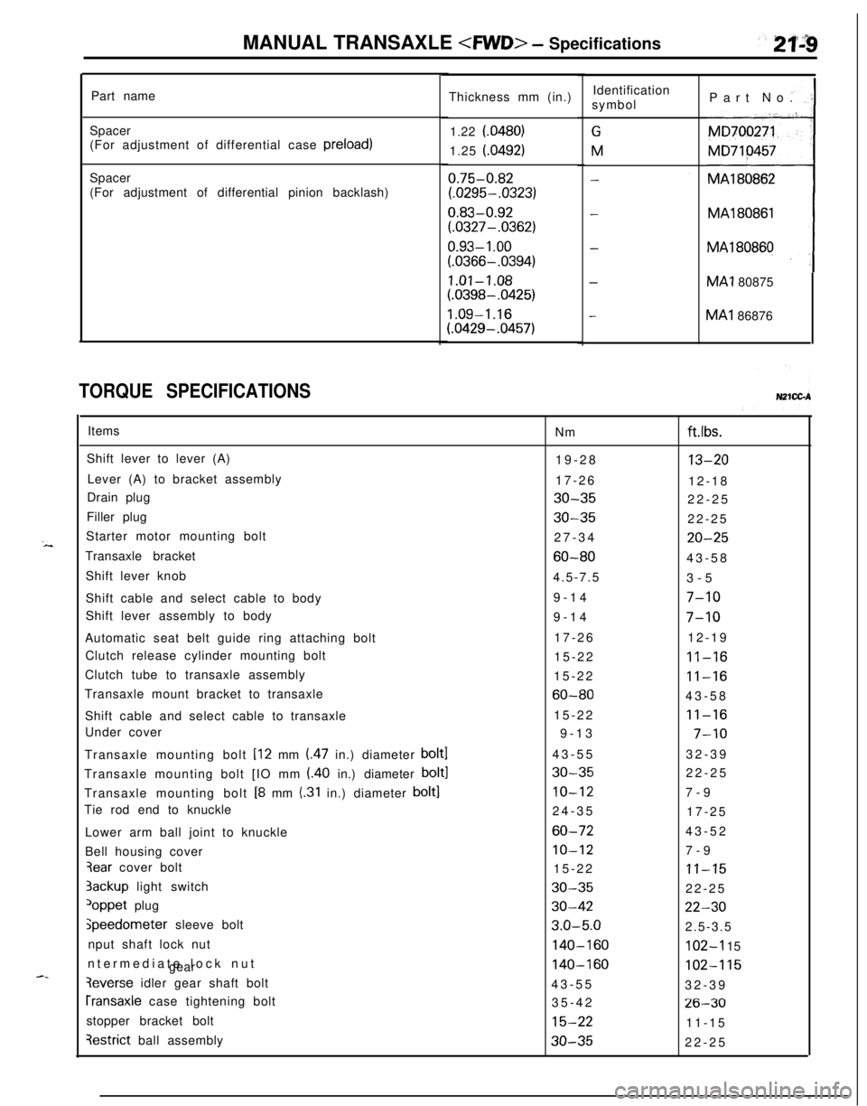
Part name
Spacer
(For adjustment of differential case preload)
Spacer
(For adjustment of differential pinion backlash)
TORQUE SPECIFICATIONSThickness mm (in.)
1.22 f.0480)
1.25 (.0492)
0.75-0.82
(.0295-.0323)
0.83-0.92
(.0327-.0362)
0.93- 1 .oo
(.0366-.0394)
1.01-1.08
(.0398-.0425)
1.09-1.16
(.0429-.0457)Identification
symbol
GM
-
-
-
-Part No.
MA180862MA1
80866MA1 80875MA1 86876
Items
Nm
Shift lever to lever (A)
19-28
Lever (A) to bracket assembly
17-26
Drain plug
30-35Filler plug
30-35Starter motor mounting bolt
27-34
Transaxle bracket
60-80Shift lever knob
4.5-7.5
Shift cable and select cable to body9-14
Shift lever assembly to body
9-14
Automatic seat belt guide ring attaching bolt17-26
Clutch release cylinder mounting bolt
15-22
Clutch tube to transaxle assembly
15-22
Transaxle mount bracket to transaxle
60-80Shift cable and select cable to transaxle15-22
Under cover
9-13
Transaxle mounting bolt [12 mm (.47 in.) diameter
bolt143-55
Transaxle mounting bolt [IO mm (.40 in.) diameter
bolt130-35Transaxle mounting bolt
[8 mm (.31 in.) diameter bolt]IO-12Tie rod end to knuckle
24-35
Lower arm ball joint to knuckle
60-72Bell housing cover
IO-123ear cover bolt
15-223ackup light switch
30-35
loppet plug30-42
jpeedometer sleeve bolt3.0-5.0nput shaft lock nut
140-160ntermediate lock nut
gear
140-160
3everse idler gear shaft bolt
43-55
rransaxle case tightening bolt
35-42
stopper bracket bolt
15-22
qestrict ball assembly30-35
ft.lbs.
13-2012-18
22-25
22-25
20-2543-58
3-5
7-10
7-1012-19
11-16
11-1643-58
11-16
7-1032-39
22-25
7-9
17-25
43-52
7-9
11-1522-25
22-302.5-3.5
102-I 15
102-11532-39
26-3011-15
22-25
Page 723 of 1216
MANUAL TRANSAXLE
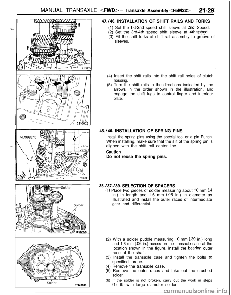
47./48. INSTALLATION OF SHIFT RAILS AND FORKS(1) Set the
lst-2nd speed shift sleeve at 2nd Speed.
(2) Set the
3rd-4th speed shift sleeve at 4th spe$d.(3) Fit the shift forks of shift rail assembly to groove of
sleeves.(4) Insert the shift rails into the shift rail holes of clutch
housing.(5) Turn the shift rails in the directions indicated by the
arrows in the order shown in the illustration, and
engage the shift lugs to control finger and interlock
plate.
45.146. INSTALLATION OF SPRING PINS
Install the spring pins using the special tool or a pin Punch.When installing, make sure that the slit of the spring pin is
aligned with the shift rail center line.
Caution
Do not reuse the spring pins.
35.137.139. SELECTION OF SPACERS
(1) Place two pieces of solder measuring about Ia mm (.4in.) in length and 1.6 mm
(.06 in.) in diameter as
illustrated and install the outer races of intermediate
gear and differential.
(2) With a solder puddle measuring
10 mm (.39 in.) long
and 1.6 mm (.06 in.) across on the transaxle case at thelocation shown in the figure, install the
bearing outer
race of the shaft.
(3) Install the transaxle case and tighten the bolts to
specified torque.
(4) Remove the transaxle case.
(5) Remove the outer races and take out the crushed
solder.(6) If the solder is not broken, carry out the work in steps
(l)-(5) with large diameter solder.
Page 725 of 1216
![MITSUBISHI ECLIPSE 1991 Service Manual MANUAL TRANSAXLE <WD> - Transaxle Assembly <F5M22>2%3T
IMD998245(5)
Insert a Phillips screwdriver [8 mm (.32 in.) shaft
diameter] into the bolt hole in the case, as shown in thefigure, and use it to MITSUBISHI ECLIPSE 1991 Service Manual MANUAL TRANSAXLE <WD> - Transaxle Assembly <F5M22>2%3T
IMD998245(5)
Insert a Phillips screwdriver [8 mm (.32 in.) shaft
diameter] into the bolt hole in the case, as shown in thefigure, and use it to](/img/19/57104/w960_57104-724.png)
MANUAL TRANSAXLE
IMD998245(5)
Insert a Phillips screwdriver [8 mm (.32 in.) shaft
diameter] into the bolt hole in the case, as shown in thefigure, and use it to align the threaded hole of the
reverse idler gear shaft with the bolt
hole in the
transaxle case.
(6) Install the reverse idler gear shaft bolt and tighten the
bolt by fingers.
(7) Tighten the all transaxle tightening bolts to specified
(8)
E$r& the reverse idle gear shaft bolt to specified
torque.
15./ 16. INSTALLATION OF LOCK NUTS(1) Install the special tool to the splined end of input shaft.
(2) Screw a bolt
(10 mm) into the hole on the periphery of
clutch housing and attach a spinner handle to the
special tool.
(3) Shift the transmission in reverse using control lever andselect lever.
(4) Tighten the lock
nut,to specified torque, while ‘using the
bolt attached in the above step as a spinner handle
stopper.(5) Loosen the lock nuts.
(6) Retighten the lock nuts to the specified torque.
(7) Stake the lock nut.
14. INSTALLATION OF SPRING PIN(1) Install the spring pin using the special tool or a pin
punch.
Caution
Do not reuse the spring pins.
Page 733 of 1216
MANUAL TRANSAXLE
/Shift rail
11-t201034er
2150008
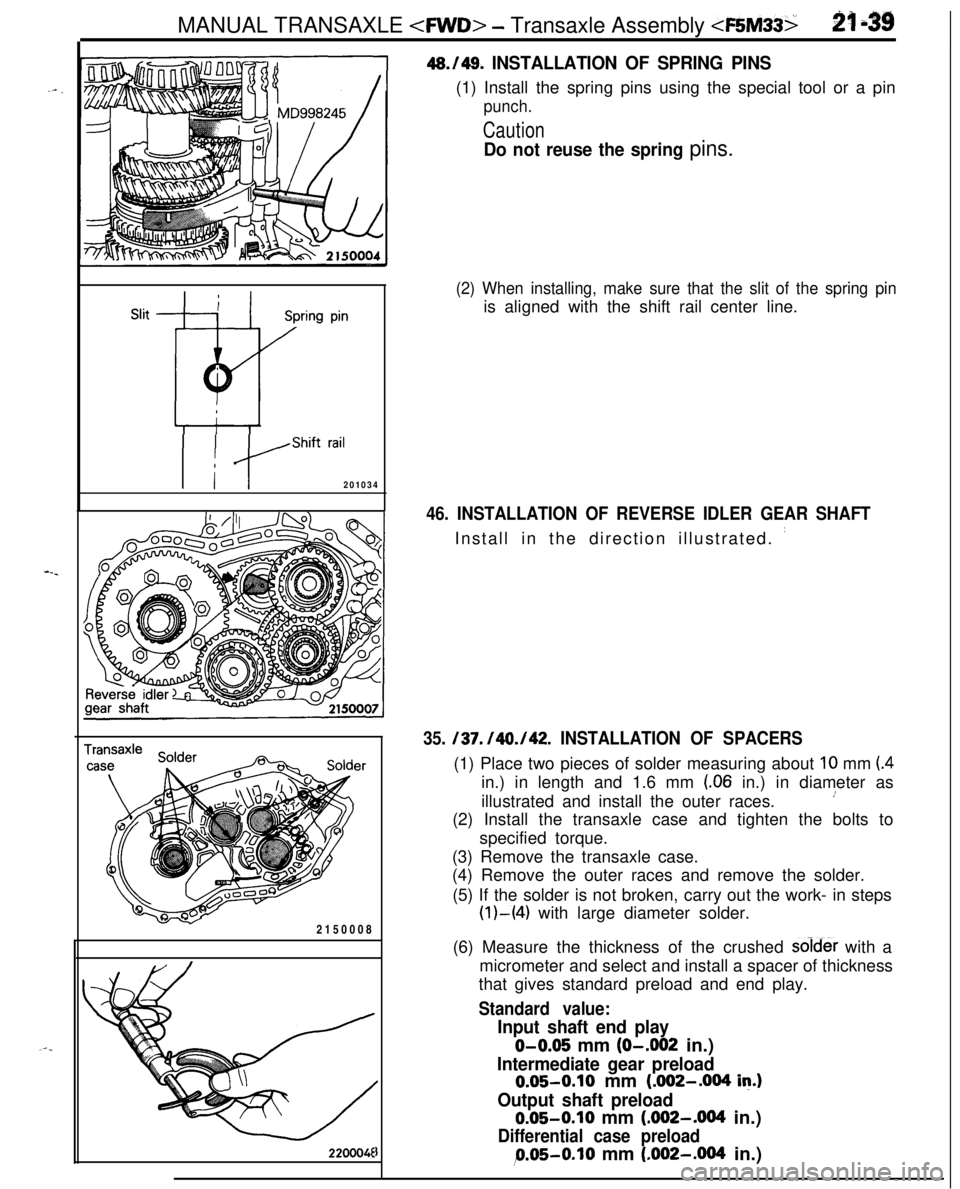
220004E46./49.
INSTALLATION OF SPRING PINS(1) Install the spring pins using the special tool or a pin
punch.
Caution
Do not reuse the spring pins.
(2) When installing, make sure that the slit of the spring pinis aligned with the shift rail center line.
46. INSTALLATION OF REVERSE IDLER GEAR SHAFTInstall in the direction illustrated.
’
35. /37. /40./42. INSTALLATION OF SPACERS(1) Place two pieces of solder measuring about
10 mm (4in.) in length and 1.6 mm
(.06 in.) in diameter as
illustrated and install the outer races.
’(2) Install the transaxle case and tighten the bolts to
specified torque.
(3) Remove the transaxle case.
(4) Remove the outer races and remove the solder.
(5) If the solder is not broken, carry out the work- in steps
(l)-(4) with large diameter solder.
(6) Measure the thickness of the crushed soid& with a
micrometer and select and install a spacer of thickness
that gives standard preload and end play.
Standard value:
Input shaft end play
O-0.05 mm (O-.002 in.)
Intermediate gear preload0.05-0.10 mm (.002-.004
in.)
Output shaft preload0.05-0.10 mm (.092-.004 in.)
Differential case preload
9.05-0.10 mm (.002-.004 in.)
Page 734 of 1216
21-40 MANUAL TRANSAXLE
1-2 mm
J
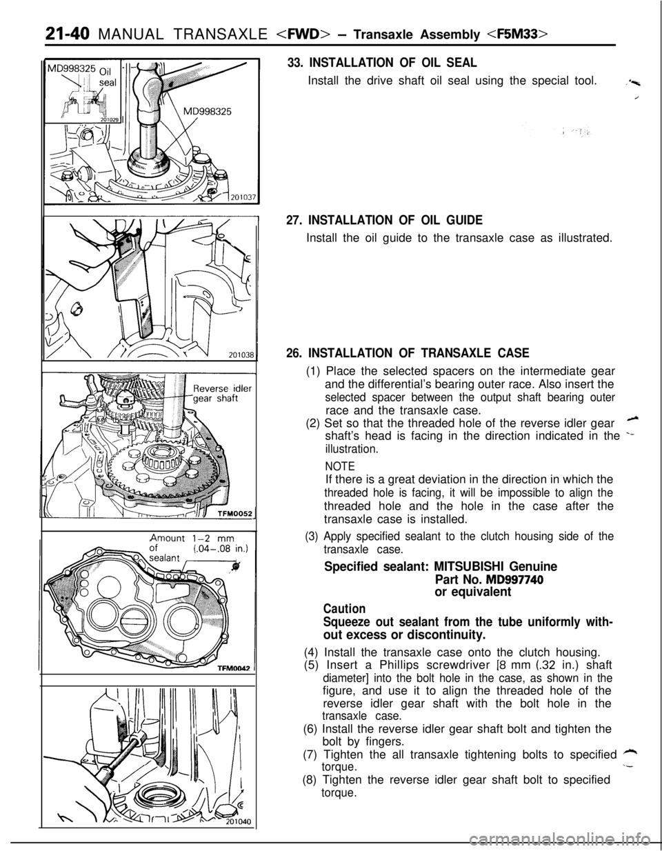
33. INSTALLATION OF OIL SEALInstall the drive shaft oil seal using the special tool.
.‘p,
/
27. INSTALLATION OF OIL GUIDEInstall the oil guide to the transaxle case as illustrated.
26. INSTALLATION OF TRANSAXLE CASE(1) Place the selected spacers on the intermediate gear
and the differential’s bearing outer race. Also insert the
selected spacer between the output shaft bearing outerrace and the transaxle case.
(2) Set so that the threaded hole of the reverse idler gear
hshaft’s head is facing in the direction indicated in the
.-
illustration.
NOTEIf there is a great deviation in the direction in which the
threaded hole is facing, it will be impossible to align thethreaded hole and the hole in the case after the
transaxle case is installed.
(3) Apply specified sealant to the clutch housing side of the
transaxle case.
Specified sealant: MITSUBISHI Genuine
Part No.
MD997740
or equivalent
Caution
Squeeze out sealant from the tube uniformly with-
out excess or discontinuity.(4) Install the transaxle case onto the clutch housing.
(5) Insert a Phillips screwdriver
18 mm (32 in.) shaft
diameter] into the bolt hole in the case, as shown in thefigure, and use it to align the threaded hole of the
reverse idler gear shaft with the bolt hole in the
transaxle case.(6) Install the reverse idler gear shaft bolt and tighten the
bolt by fingers.
(7) Tighten the all transaxle tightening bolts to specified
*
torque.,-(8) Tighten the reverse idler gear shaft bolt to specified
torque.
Page 735 of 1216
MANUAL TRANSAXLE
10 mm (.40 in.)
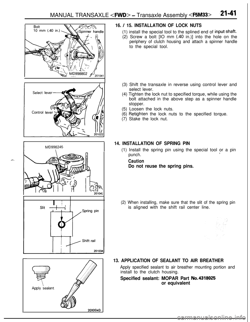
16. / 15. INSTALLATION OF LOCK NUTS(1) install the special tool to the splined end of inputshaft.
(2) Screw a bolt [IO mm
(.40 in.)] into the hole on the
periphery of clutch housing and attach a spinner handleto the special tool.
MD998245\ISlit
,+i 1I I
r
Spring pin
, Shift rail(3) Shift the transaxle in reverse using control lever and
select lever.
(4) Tighten the lock nut to specified torque, while using the
bolt attached in the above step as a spinner handle
stopper.(5) Loosen the lock nuts.
(6)
&tighten the lock nuts to the specified torque.
(7) Stake the lock nut.
14. INSTALLATION OF SPRING PIN(1) Install the spring pin using the special tool or a pin
punch.,
Caution
Do not reuse the spring pins.
(2) When installing, make sure that the slit of the spring pinis aligned with the shift rail center line.
13. APPLICATION OF SEALANT TO AIR BREATHER
Apply specified sealant to air breather mounting portion andinstall to the clutch housing.
Specified sealant: MOPAR Part No.4318025
or equivalent
Page 759 of 1216
bierential Assembl /MANUAL TRANSAXLE
, .Bearing
TFYOOIO
The numerals 0 to (8 indicate1 the tiqhtening Gequeice.210029I
SPEEDOMETER GEAR ASSEMBLY
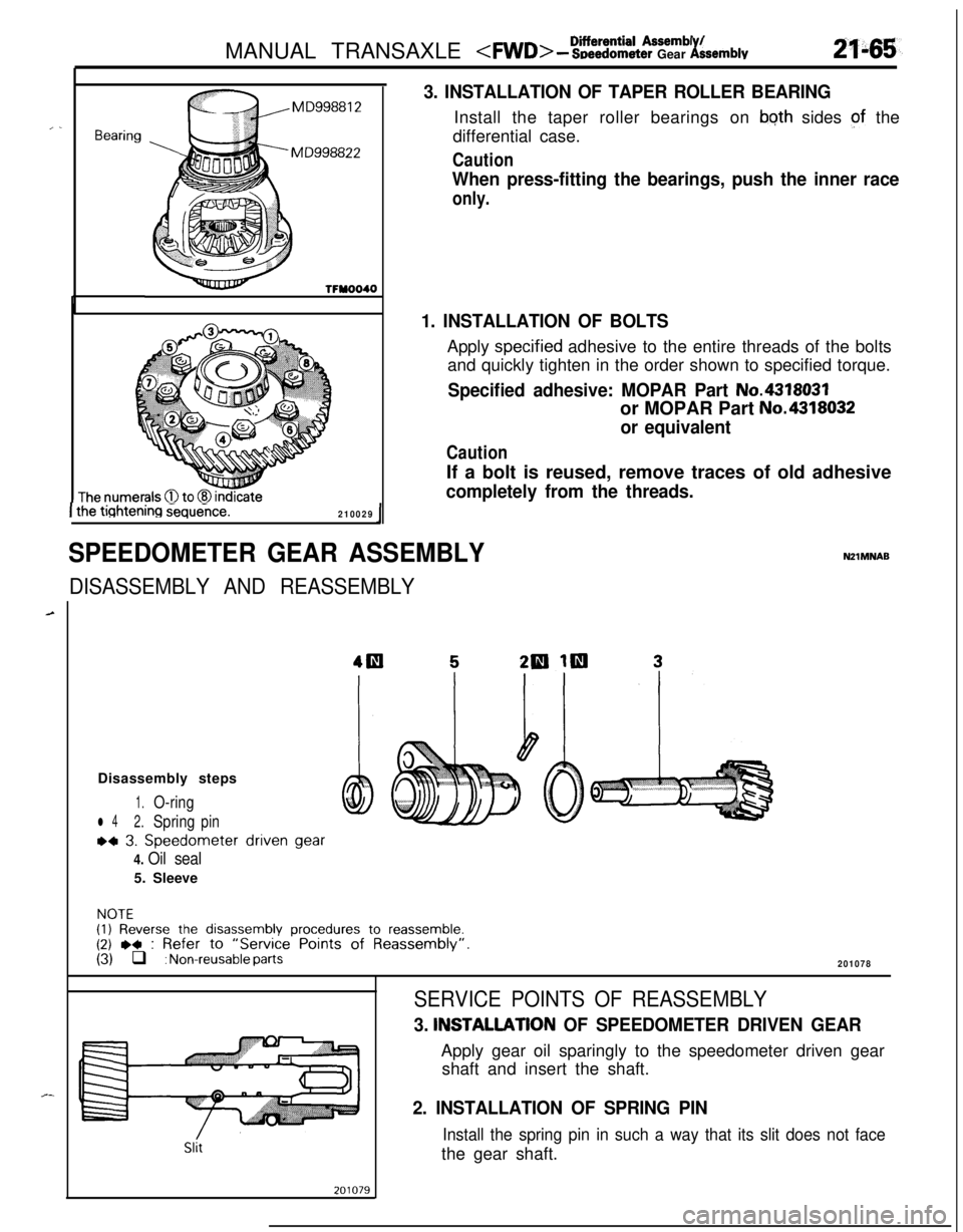
3. INSTALLATION OF TAPER ROLLER BEARINGInstall the taper roller bearings on
bqth sides of the
differential case.
Caution
When press-fitting the bearings, push the inner race
only.
1. INSTALLATION OF BOLTSApply
spec.ified adhesive to the entire threads of the bolts
and quickly tighten in the order shown to specified torque.
Specified adhesive: MOPAR Part No.4318031or MOPAR Part
No.4318032
or equivalent
CautionIf a bolt is reused, remove traces of old adhesive
completely from the threads.
DISASSEMBLY AND REASSEMBLY
NZlMNABDisassembly steps
1.O-ring
l 42.Springpin
~4 3. Speedometer driven gear
4. Oil seal5. Sleeve
NOTE(1) Reverse the disassembly procedures to reassemble.(2) ,+ : Refer to “Service Points of Reassembly”.(3) q : Non-reusable parts201078
Slit
SERVICE POINTS OF REASSEMBLY
3. INSTALLATlON OF SPEEDOMETER DRIVEN GEARApply gear oil sparingly to the speedometer driven gear
shaft and insert the shaft.
2. INSTALLATION OF SPRING PIN
Install the spring pin in such a way that its slit does not facethe gear shaft.
Page 763 of 1216
MANUAL TRANSAXLE
2f.46g
\ ,...,
,,, .,
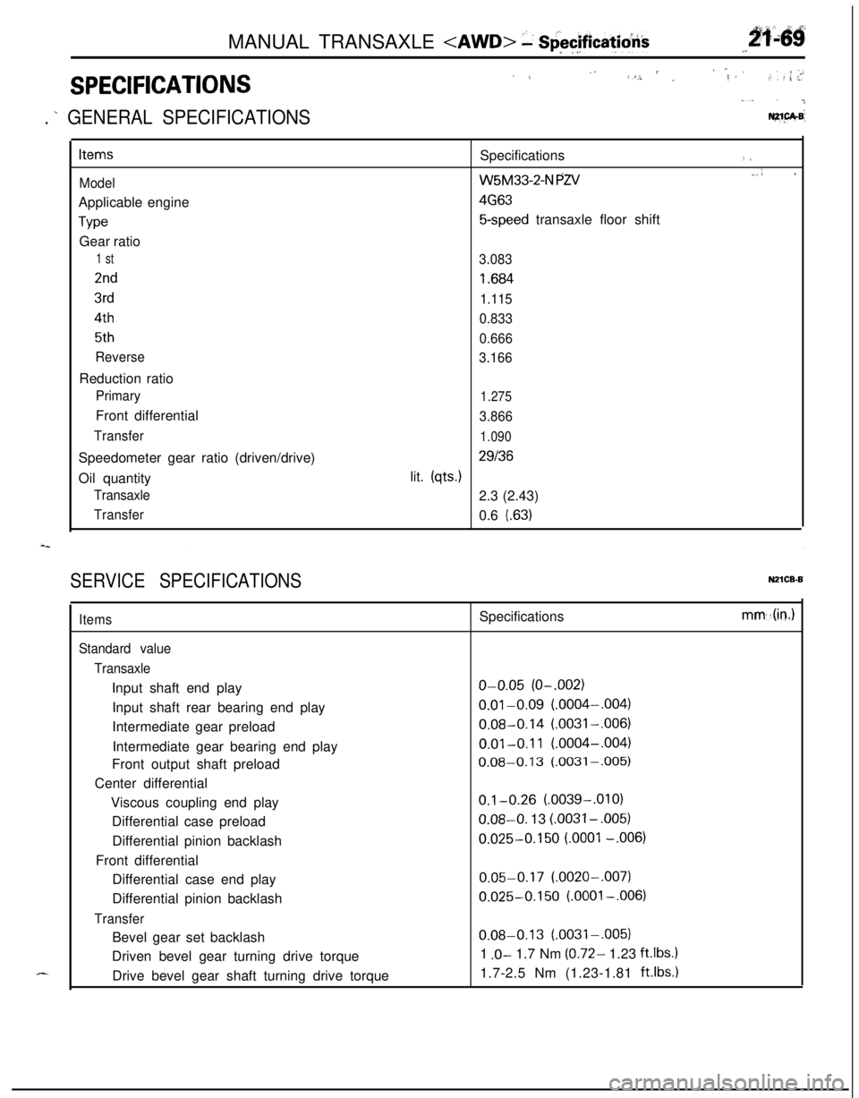
SPECIFICATIONS
1 L,‘S. / ,‘; ,< ’,f. : ,: ; .>r
“. . ..&
. ’ GENERAL SPECIFICATIONSNZ1.pA.B’
Items
ModelApplicable engine
TypeGear ratio
1 st
2nd
3rd
4th
5th
ReverseReduction ratio
PrimaryFront differential
TransferSpeedometer gear ratio (driven/drive)
Oil quantity
Transaxle
TransferSpecifications
(I
W5M33-2-N PZV.,A I
4G63
5-speed transaxle floor shift
3.083
I .684
1.115
0.833
0.666
3.166
1.275
3.866
1.090
29136lit.
(qts.)2.3 (2.43)
0.6
l.63)
SERVICE SPECIFICATIONSN21CB-B
d-...
Items
Standard value
TransaxleInput shaft end play
Input shaft rear bearing end play
Intermediate gear preload
Intermediate gear bearing end play
Front output shaft preload
Center differential
Viscous coupling end play
Differential case preload
Differential pinion backlash
Front differential
Differential case end play
Differential pinion backlash
TransferBevel gear set backlash
Driven bevel gear turning drive torque
Drive bevel gear shaft turning drive torqueSpecifications
o-0.05 (O-.002)
0.01-0.09 (.0004-,004)
0.08-0.14 (.0031-,006)
0.01-0.11 (.0004-,004)
0.08-0.13 (.0031-,005)
0.1-0.26 (.0039-.OlO)0.08-O. 13
LOO31 - ,005)
0.025-0.150 LOO01 -.006)
0.05-0.17 (.0020-,007)
0.025-0.150 (.OOOl-,006)
0.08-0.13 (.0031-.005)
1
.O- 1.7 Nm (0.72- 1.23 ft.lbs.11.7-2.5 Nm (1.23-1.81
ft.lbs.1
mm,.(in.)