torque MITSUBISHI ECLIPSE 1991 Repair Manual
[x] Cancel search | Manufacturer: MITSUBISHI, Model Year: 1991, Model line: ECLIPSE, Model: MITSUBISHI ECLIPSE 1991Pages: 1216, PDF Size: 67.42 MB
Page 509 of 1216
FUEL SYSTEM - Service Adjustment Procedures <2.0L Engine>14-55
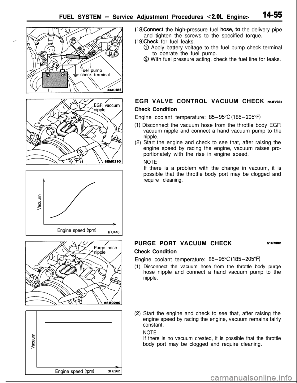
(18)Connect the high-pressure fuel hose,,to the delivery pipe
and tighten the screws to the specified torque.
(19)Check for fuel leaks.
@I Apply battery voltage to the fuel pump check terminal
to operate the fuel pump.
@ With fuel pressure acting, check the fuel line for leaks.
A
E2li:>
/ )
Engine speed (rpm)lFU4l6EGR VALVE CONTROL VACUUM CHECK
NlQFVBBlCheck Condition
Engine coolant temperature:
85-95°C (185-205°F)
(1) Disconnect the vacuum hose from the throttle body EGR
vacuum nipple and connect a hand vacuum pump to the
nipple.(2) Start the engine and check to see that, after raising the
engine speed by racing the engine, vacuum raises pro-
portionately with the rise in engine speed.
NOTEIf there is a problem with the change in vacuum, it is
possible that the throttle body port may be clogged and
require cleaning.PURGE PORT VACUUM CHECK
Check Condition
N14FVBClEngine coolant temperature:
85-95°C (185-205°F)
(1) Disconnect the vacuum hose from the throttle body purge
hose nipple and connect a hand vacuum pump to the
nipple.
Engine speed (rpm)3FU262(2) Start the engine and check to see that, after raising the
engine speed by racing the engine, vacuum remains fairly
constant.
NOTE
If there is no vacuum created, it is possible that the throttlebody port may be clogged and require cleaning.
Page 516 of 1216
14-62FUEL SYSTEM - MPI System Inspection <1.8L Engine>
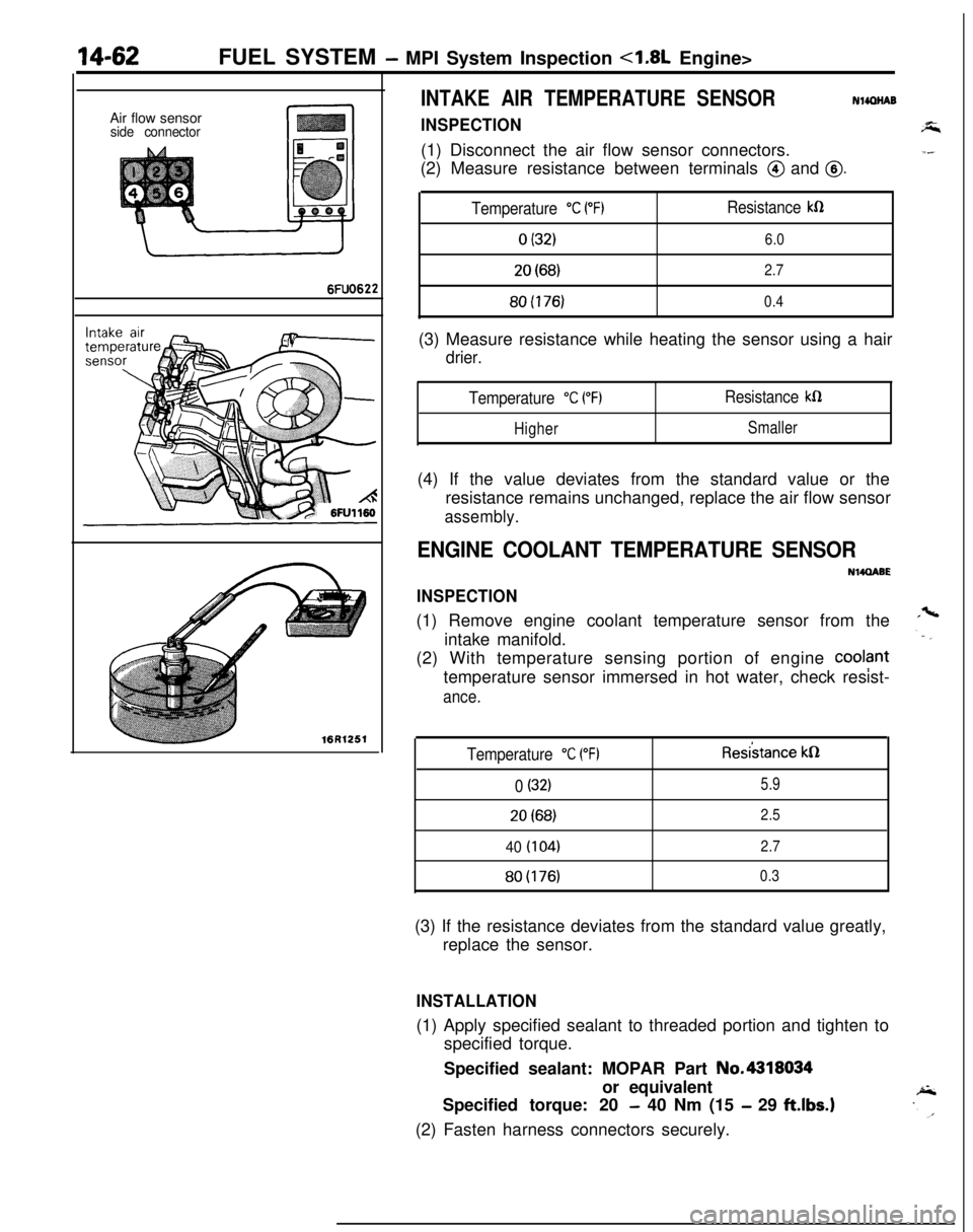
INTAKE AIR TEMPERATURE SENSORNlmNABAir flow sensor
side connectorINSPECTION(1) Disconnect the air flow sensor connectors.
(2) Measure resistance between terminals
@ and @.
6FUO622
Temperature “C PF)Resistance kR
0 (32)6.0
20(68)2.780(176)
0.4(3) Measure resistance while heating the sensor using a hair
drier.
Temperature “C (“F)Resistance kfi
HigherSmaller(4) If the value deviates from the standard value or the
resistance remains unchanged, replace the air flow sensor
assembly.
ENGINE COOLANT TEMPERATURE SENSOR
NWQABE
INSPECTION(1) Remove engine coolant temperature sensor from the
intake manifold.
(2) With temperature sensing portion of engine
cool?nttemperature sensor immersed in hot water, check resist-
ance.16R1251
Temperature “C (“F)Resi’stance kQ
0 (32)5.920(68)
2.5
40 (104)2.7
80(176)0.3(3) If the resistance deviates from the standard value greatly,
replace the sensor.
INSTALLATION(1) Apply specified sealant to threaded portion and tighten to
specified torque.
Specified sealant: MOPAR Part No.4318034
or equivalent
Specified torque: 20
- 40 Nm (15 - 29 ftlbs.)(2) Fasten harness connectors securely.
Page 517 of 1216
FUEL SYSTEM - MPI Svstem Inspection <1.8L Engine>18-63
Throttle position sensor
Groundoutput
Sensorpower
SUPPlY(5V)
1 FUO507
6FU1244Motor
Dosition sensor connector
(motor ‘side, front view)
T
6FU1247Motor position sensor
connector(motor side, front view)
6FU1252
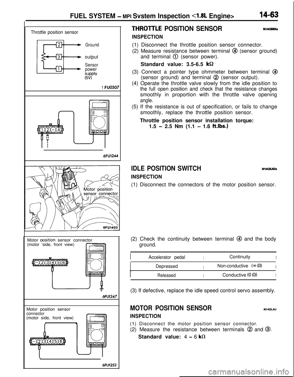
THROITLE POSITION SENSOR
INSPECTION
Nl4OBBKa(1) Disconnect the throttle position sensor connector.
(2) Measure resistance between terminal
@I (sensor ground)
and terminal
@ (sensor power).
Standard value: 3.5-6.5
kGI(3) Connect a pointer type ohmmeter between terminal
@(sensor ground) and terminal
@ (sensor output).
(4) Operate the throttle valve slowly from the idle position to
the full open position and check that the resistance changessmoothly in proportion with the throttle valve opening
angle.(5) If the resistance is out of specification, or fails to change
smoothly, replace the throttle position sensor.
Throttle position sensor installation torque:
1.5
- 2.5 Nm (1.1 - 1.6 ftlbs.)
IDLE POSITION SWITCH
INSPECTION
N14QKADa(1) Disconnect the connectors of the motor position sensor.
(2) Check the continuity between terminal
@ and the body
ground.
IAccelerator pedalIContinuityI
DepressedINon-conductive (@J fl)I
ReleasedIConductive (0 fl)I(3) If defective, replace the idle speed control servo assembly.
MOTOR POSITION SENSOR
INSPECTION
N140lAJ(1) Disconnect the motor position sensor connector.
(2) Measure the resistance between terminals
@ and 0.Standard value: 4
- 6 kfi
Page 518 of 1216
14-64FUEL SYSTEM -MPI System Inspection <1.8L Engine>
Idle speed controlservo connector
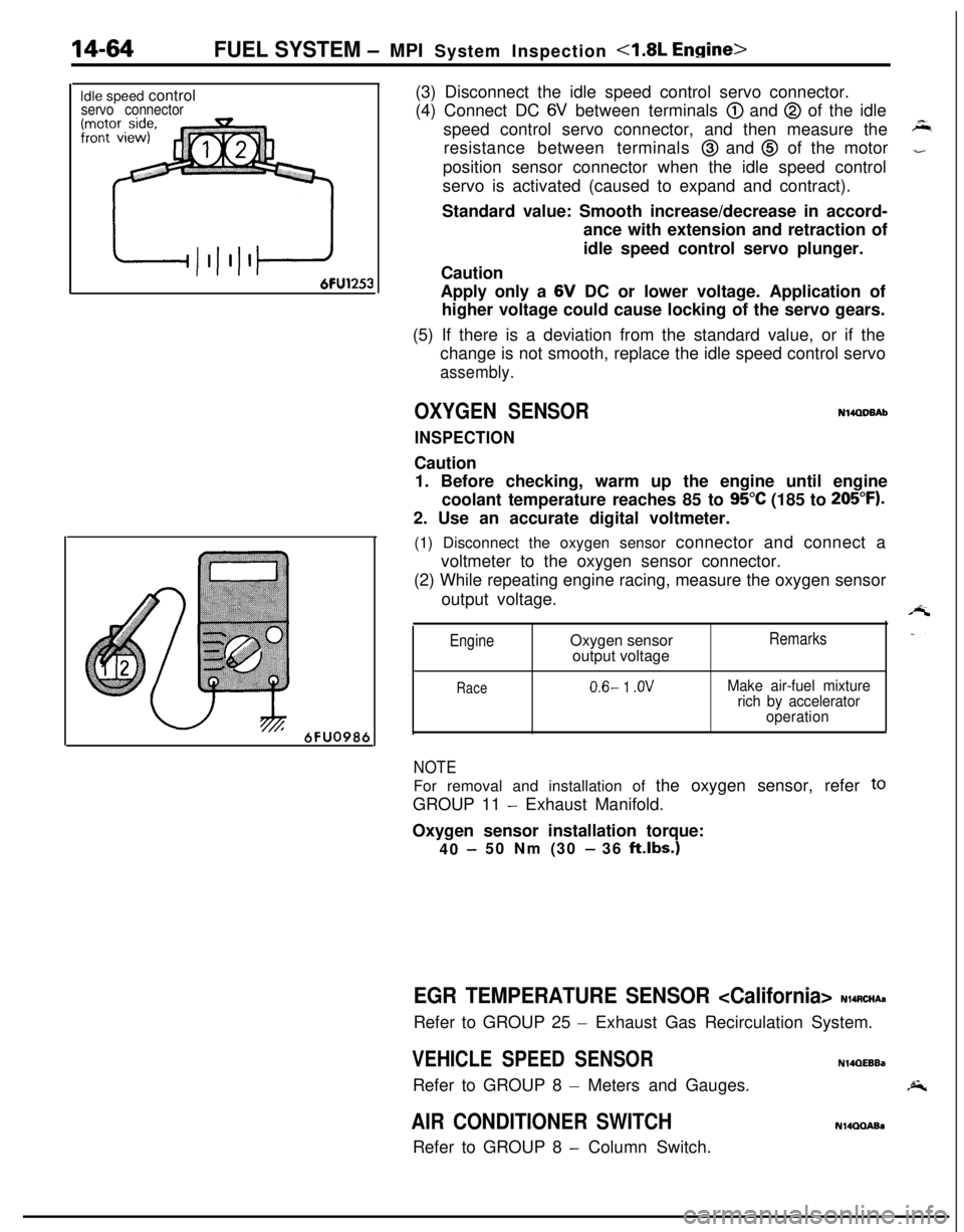
6FU098t(3) Disconnect the idle speed control servo connector.
(4) Connect DC
6V between terminals @) and @ of the idle
speed control servo connector, and then measure the
resistance between terminals
@ and @ of the motor
position sensor connector when the idle speed control
servo is activated (caused to expand and contract).
Standard value: Smooth increase/decrease in accord-
ance with extension and retraction of
idle speed control servo plunger.
Caution
Apply only a 6V DC or lower voltage. Application of
higher voltage could cause locking of the servo gears.
(5) If there is a deviation from the standard value, or if the
change is not smooth, replace the idle speed control servo
assembly.
OXYGEN SENSORN14QDBAb
INSPECTIONCaution
1. Before checking, warm up the engine until engine
coolant temperature reaches 85 to
95°C (185 to 205°F).2. Use an accurate digital voltmeter.
(1) Disconnect the oxygen sensor connector and connect a
voltmeter to the oxygen sensor connector.
(2) While repeating engine racing, measure the oxygen sensor
output voltage.
EngineOxygen sensor
output voltageRemarks
Race0.6- 1 .OVMake air-fuel mixture
rich by accelerator
operation
NOTEFor removal and installation of the oxygen sensor, refer
toGROUP 11
- Exhaust Manifold.
Oxygen sensor installation torque:
40
-50 Nm (30 - 36 klbs.)
EGR TEMPERATURE SENSOR
- Exhaust Gas Recirculation System.
VEHICLE SPEED SENSORN14QEEBaRefer to GROUP 8
- Meters and Gauges.
AIR CONDITIONER SWITCHRefer to GROUP 8
- Column Switch.
N14QQABa
Page 531 of 1216
FUEL SYSTEM - MPI Svstem InsDection <2.0L DOHC Engine>14-77INSTALLATION
(1) Apply specified sealant to threaded portion and tighten to
specified torque.
Specified sealant: MOPAR Part No.4318034 or
equivalent
Specified torque: 20
- 40 Nm (15 - 29 ft.lbs.1(2) Fasten harness connectors securely.
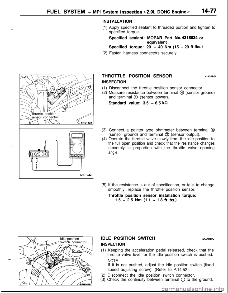
THROTTLE POSITION SENSOR
INSPECTION
N14QBBKl(1) Disconnect the throttle position sensor connector.
(2) Measure resistance between terminal
@I (sensor ground)
and terminal
@ (sensor power).
Standard value: 3.5
- 6.5 kR(3) Connect a pointer type ohmmeter between terminal
@I(sensor ground) and terminal
@ (sensor output).
(4) Operate the throttle valve slowly from the idle position to
the full open position and check that the resistance changessmoothly in proportion with the throttle valve opening
angle.
6FU1244(5) If the resistance is out of specification, or fails to change
smoothly, replace the throttle position sensor.
Throttle position sensor installation torque:
1.5
- 2.5 Nm (1.1 - 1.8 ft.lbs.)
J II\/ hFU1419IDLE POSITION SWITCH
INSPECTION
N14QKAEa(1) Keeping the acceleration pedal released, check that the
throttle valve lever or the idle position switch is pushed.
NOTEIf it is not pushed, adjust the idle position switch (fixed
speed adjusting screw). (Refer to
P.14-52.)(2) Disconnect the idle position switch connector.
(3) Check the continuity between terminal
@) to the ground.
Page 532 of 1216
FUEL SYSTEM - MPI System Inspection <2.0L DOHC Engine>
6FUO999
Accelerator pedal
DepressedContinuity .
Non-conductive
(03 fl)
ReleasedIConductive (0 fl)I(4) Replace the idle position switch if faulty.
NOTE
For replacement procedure, refer to the idle position switch(fixed speed adjusting screw) adjustment section
(P.14-
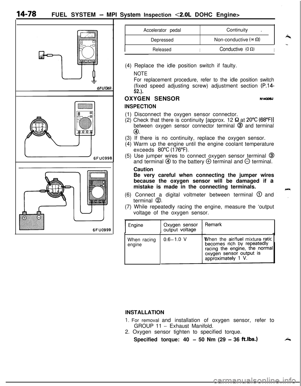
52.).OXYGEN SENSOR
NllQDeJ
INSPECTION(1) Disconnect the oxygen sensor connector.
(2) Check that there is continuity [approx. 12
52 at 20°C (68”F)l
between oxygen sensor connector terminal @ and terminal
GO.(3) If there is no continuity, replace the oxygen sensor.
(4) Warm up the engine until the engine coolant temperature
exceeds
80°C (176°F).(5) Use jumper wires to connect oxygen sensor terminal
@and terminal
@ to the battery @ terminal and 0 terminal.
Caution
Be very careful when connecting the jumper wires
because the oxygen sensor will be damaged if a
mistake is made in the connecting terminals.
(6) Connect a digital voltmeter between terminal
@ and
terminal
0.(7) While repeatedly racing the engine, measure the ‘output
voltage of the oxygen sensor.
When racing
engineWhen the
air/fuel mixture raticINSTALLATION
1. For removal and installation of oxygen sensor, refer to
GROUP 11
- Exhaust Manifold.
2. Oxygen sensor tighten to specified torque.
Specified torque: 40
- 50 Nm (29 - 36 ft.lbs.)
Page 550 of 1216
FUEL SYSTEM- Fuel Tank
Flare nut
Se&e side 03~043
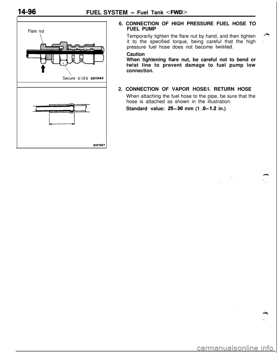
03FOO76. CONNECTION OF HIGH PRESSURE FUEL HOSE TO
FUEL PUMP
Temporarily tighten the flare nut by hand, and then tighten
;Jtit to the specified torque, being careful that the high
’pressure fuel hose does not become twisted.
Caution
When tightening flare nut, be careful not to bend or
twist line to prevent damage to fuel pump low
connection.2. CONNECTION OF VAPOR HOSE/l. RETURN HOSE
When attaching the fuel hose to the pipe, be sure that the
hose is attached as shown in the illustration.
Standard value:
25-30 mm (1 .O-1.2 in.)
Page 558 of 1216
FUEL SYSTEM - Fuel Line and VaDor Line/Fuel Filter
High-pressur
hose
f+-----Eye bolt
Gasket
Fuel filter
Flare nut
Fuel main
pipe
\-Apply engine
&ring Oi’
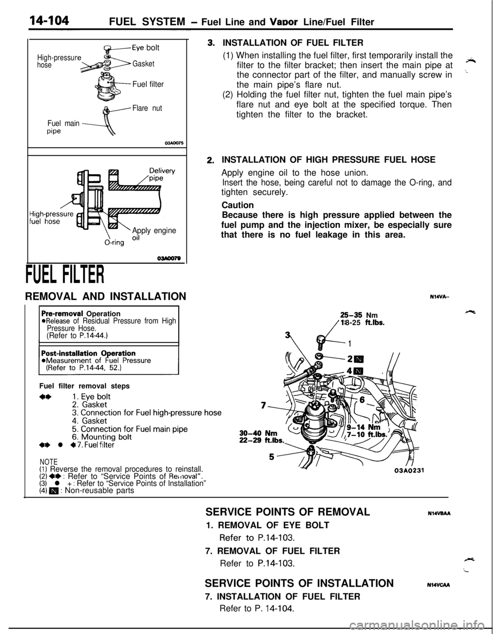
FUEL FILTERREMOVAL AND INSTALLATION3.2.INSTALLATION OF FUEL FILTER
(1) When installing the fuel filter, first temporarily install the
filter to the filter bracket; then insert the main pipe at
‘*the connector part of the filter, and manually screw in
..the main pipe’s flare nut.
(2) Holding the fuel filter nut, tighten the fuel main pipe’s
flare nut and eye bolt at the specified torque. Then
tighten the filter to the bracket.
Pre-removal Operation@Release of Residual Pressure from High
Pressure Hose.
(Refer to P.14-44.)IIFuel filter removal steps
**1. Eye bolt2. Gasket3. Connection for Fuel high-pressure hose
4. Gasket
5. Connection for Fuel main pipe6. Mounting bolt+e l 4 7. Fuel filter
NOTE(1) Reverse the removal procedures to reinstall.(2) +e : Refer to “Service Points of Removal”.(3) l + : Refer to “Service Points of Installation”(4) m : Non-reusable partsINSTALLATION OF HIGH PRESSURE FUEL HOSE
Apply engine oil to the hose union.
Insert the hose, being careful not to damage the O-ring, andtighten securely.
Caution
Because there is high pressure applied between the
fuel pump and the injection mixer, be especially sure
that there is no fuel leakage in this area.
N14VA-25-35 Nm
18-25
ft.lbs.
vd-
7’
1
Y03A0231SERVICE POINTS OF REMOVAL
NlIVBAA1. REMOVAL OF EYE BOLT
Refer to P.14-103.
7. REMOVAL OF FUEL FILTER
Refer to
P.14-103.SERVICE POINTS OF INSTALLATION
7. INSTALLATION OF FUEL FILTER
Refer to P. 14-104.
N14VCAA
Page 559 of 1216
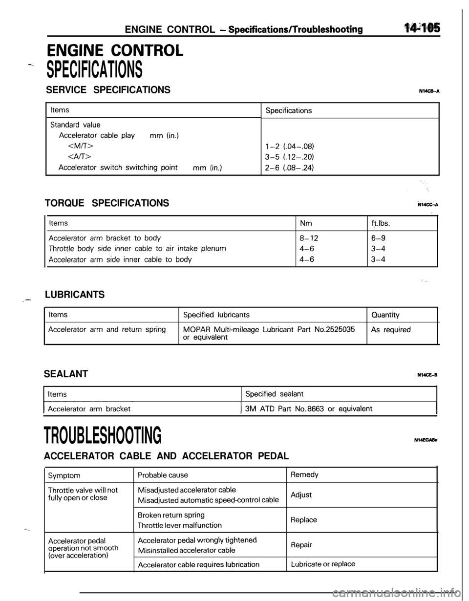
ENGINE CONTROL - SpecificatiodTroubleshooting
ENGINE CONTROL
-.
SPECIFICATIONS
SERVICE SPECIFICATIONSN14CEA
Items
Standard value
Accelerator cable playmm (in.)
dfi>
Accelerator switch switching pointmm (in.)Specifications
1-2 (.04-.08)
3-5 (.12-.20)
2-6 (.08-.24)
N14CkATORQUE SPECIFICATIONS
Items
Accelerator arm bracket to body
Throttle body side inner cable to air intake plenum
Accelerator arm side inner cable to body
Nmft.lbs.
8-126-9
4-63-4
4-63-4
I
: j,
LUBRICANTS_-
Items
Accelerator arm and return spring
Specified lubricants
MOPAR Multi-mileage Lubricant Part No.2525035
or equivalentQuantityAs required
SEALANTN14CE.-BItems
I-- ~Accelerator arm bracket
Specified sealant
I3M ATD Part No.8663 or equivalentI
-.
TROUBLESHOOTINGN14EGABa
ACCELERATOR CABLE AND ACCELERATOR PEDAL
Symptom
Throttle valve will notfully
open or close
Probable causeRemedyMisadjusted
accelerator cableMisadjusted automatic
speed-control cableAdjust
Broken return springThrottle
lever malfunctionReplace
Accelerator pedaloperation not smooth(over acceleration)
Accelerator pedal wrongly tightenedMisinstalled
accelerator cable
Accelerator cable requires lubrication
Repair
Lubricate or replace
Page 563 of 1216
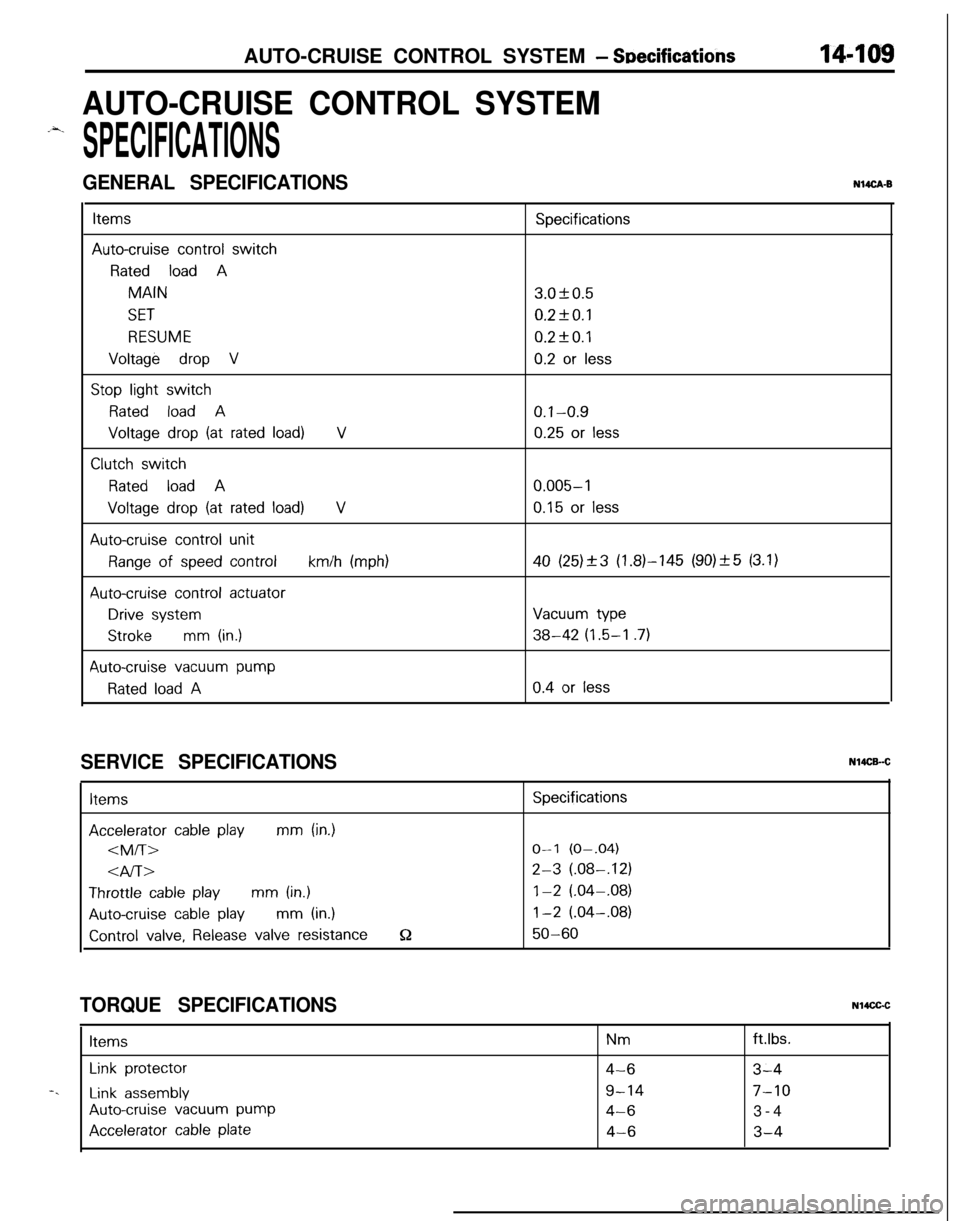
AUTO-CRUISE CONTROL SYSTEM - Snecifications14-109
AUTO-CRUISE CONTROL SYSTEM
.-4.
SPECIFICATIONS
GENERAL SPECIFICATIONSNUCA-B
ItemsSpecifications
Auto-cruise control switch
Rated load AMAIN3.OkO.5
SET0.2fO.l
RESUME0.2kO.l
Voltage drop V0.2 or less
Stop light switch
Rated load A0.1-0.9
Voltage drop (at rated load)V0.25 or less
Clutch switch
Rated load A0.005-l
Voltage drop (at rated load)V0.15 or less
Auto-cruise control unit
Range of speed controlkm/h (mph)40 (25)_+3 (1.81-145 (90)_+5 (3.1)
Auto-cruise control actuator
Drive systemVacuum type
Strokemm (in.)38-42 (1.5-I .7)
Auto-cruise vacuum pump
Rated load A0.4 or less
SERVICE SPECIFICATIONSItems
Accelerator cable playmm (in.)
4l-bThrottle
cable playmm (in.)
Auto-cruise cable playmm (in.)
Control valve, Release valve resistanceQ
Specifications
O-l (O-.04)
2-3 (.08-,121
1-2 (.04-.08)
1-2 (.04-.08)
50-60
TORQUE SPECIFICATIONSN14CGCItems
Nmftlbs.
Link protector4-63-4-.
Link assembly9-147-10
Auto-cruise vacuum pump4-63-4
Accelerator cable plate4-63-4