torque MITSUBISHI ECLIPSE 1991 Manual Online
[x] Cancel search | Manufacturer: MITSUBISHI, Model Year: 1991, Model line: ECLIPSE, Model: MITSUBISHI ECLIPSE 1991Pages: 1216, PDF Size: 67.42 MB
Page 624 of 1216
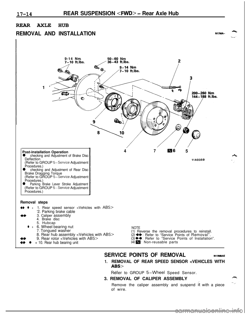
17-14REAR SUSPENSION
REMOVAL AND INSTALLATIONNl’IMA--1’9-14 Nm
50-60 Nm
Post-installation Operation
l checking and Adjustment of Brake DiscDeflection
(Refer to GROUP
5-Service AdjustmentProcedures.)l checking and Adjustment of Rear DiscBrake Dragging Torque
(Refer to GROUP
5-Service AdjustmentProcedures.)l Parking Brake Lever Stroke Adjustment(Refer to GROUP 5%Service AdjustmentProcedures.)
47m6 5
llA0359
Removal steps
+* l +1. Rear speed sensor
‘2. Parking brake cable
4*3. Caliper assembly
4. Brake disc
5. Hubcap
l +6. Wheel bearing nut
7. Tongued washer
8. Rear hub assembly
4*9. Rear rotor
+I) l + 10. Rear hub bearing unit
NOTE(I) Reverse the removal procedures to reinstall.(2) +e : Refer to “Service Points of Removal”.(3) I)+ : Refer to “Service Points of Installation”.(4) m : Non-reusable parts
SERVICE POINTS OF REMOVALNVMBAE
1.REMOVAL OF REAR SPEED SENSOR
R6fer to GROUP 5-Wheel Speed Sensor.
3. REMOVAL OF CALIPER ASSEMBLY
Remove the caliper assembly and suspend
it with a piece
of wire.
Page 627 of 1216
REAR SUSPENSION
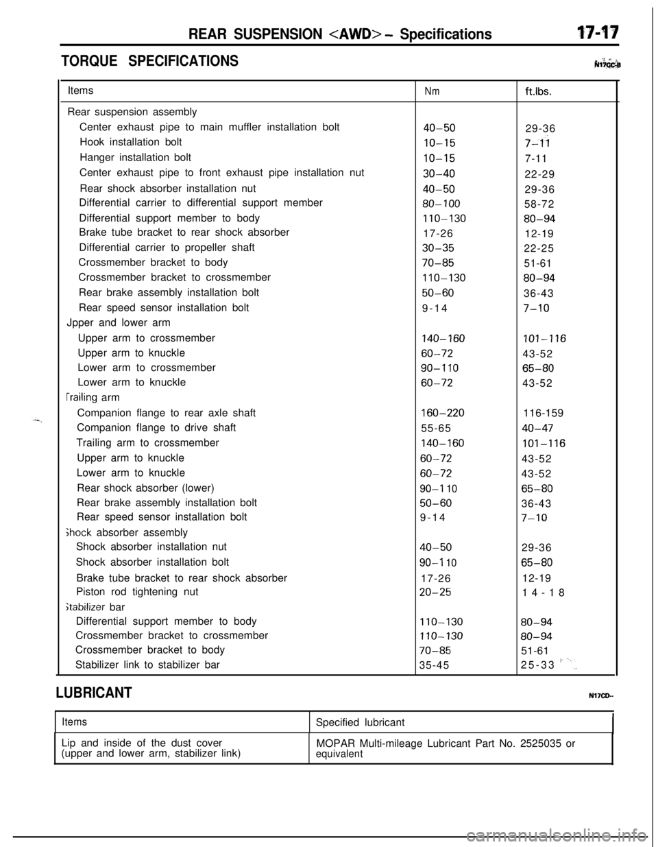
TORQUE SPECIFICATIONS. ‘2 +’ iiNl?GGbItems
Rear suspension assembly
Center exhaust pipe to main muffler installation bolt
Hook installation bolt
Hanger installation bolt
Center exhaust pipe to front exhaust pipe installation nut
Rear shock absorber installation nut
Differential carrier to differential support member
Differential support member to body
Brake tube bracket to rear shock absorber
Differential carrier to propeller shaft
Crossmember bracket to body
Crossmember bracket to crossmember
Rear brake assembly installation bolt
Rear speed sensor installation bolt
Jpper and lower arm
Upper arm to crossmember
Upper arm to knuckle
Lower arm to crossmember
Lower arm to knuckle
[railing arm
Companion flange to rear axle shaft
Companion flange to drive shaft
Trailing arm to crossmember
Upper arm to knuckle
Lower arm to knuckle
Rear shock absorber (lower)
Rear brake assembly installation bolt
Rear speed sensor installation bolt
Ghock absorber assembly
Shock absorber installation nut
Shock absorber installation bolt
Brake tube bracket to rear shock absorber
Piston rod tightening nut
stabilizer bar
Differential support member to body
Crossmember bracket to crossmember
Crossmember bracket to body
Stabilizer link to stabilizer bar
Nmft.lbs.
40-5029-36
IO-157-ii
IO-157-11
30-4022-29
40-5029-36
80-10058-72
110-13080-9417-26
12-19
30-3522-25
70-8551-61
110-13080-94
50-6036-43
9-14
7-10
140-160101-116
60-7243-52
90-I 1065-80
60-7243-52
160-220116-159
55-65
40-47
140-160101-116
60-7243-52
60-7243-52
90-I 1065-80
50-6036-43
9-14
7-10
40-5029-36
90-l 1065-8017-2612-19
20-2514-18
110-13080-94
110-13080-94
70-8551-61
35-4525-33
I'-'.
LUBRICANTNl’ICD-
ItemsSpecified lubricant
Lip and inside of the dust cover
(upper and lower arm, stabilizer link)MOPAR Multi-mileage Lubricant Part No. 2525035 or
equivalent
Page 636 of 1216
17-26REAR SUSPENSION
I12A0090
wrench12A0099
, MB990800Dust cover
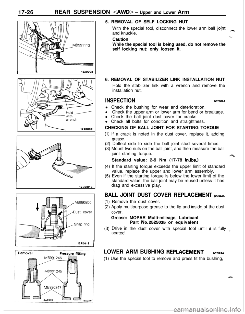
Snap ring5. REMOVAL OF SELF LOCKING NUT
With the special tool, disconnect the lower arm ball
jo’intand knuckle.3cCaution
wtWhile the special tool is being used, do not remove the
self locking nut; only loosen it.
6. REMOVAL OF STABILIZER LINK INSTALLATION NUT
Hold the stabilizer link with a wrench and remove the
installation nut.
INSPECTIONN17SCAAl Check the bushing for wear and deterioration.
lCheck the upper arm or lower arm for bend or breakage.
l Check the ball joint dust cover for cracks.
l Check all bolts for condition and straightness.
CHECKING OF BALL JOINT FOR STARTING TORQUE
(1) If a crack is noted in the dust cover, replace it, adding
grease.(2) Deflect side to side the ball joint stud several times.
(3) Mount two nuts on the ball joint, and then measure the ball
joint starting torque.
“,Standard value: 2-9 Nm (17-78
in.lbs.)(4) If the starting torque exceeds the upper limit of standard
value, replace the upper and lower arm assembly.
(5) Even if the starting torque is below the lower limit of the
standard value, the ball joint may be reused unless it has
drag and excessive play.
BALL JOINT DUST COVER REPLACEMENT N17s~(1) Remove the dust cover.
(2) Apply multipurpose grease to the lip and
inside,of the dust
cover.Grease: MOPAR Multi-mileage, Lubricant
Part No.2525035 or equivalent
(3)
:;Fedin the dust cover with special tool until i,, is fully -T
LOWER ARM BUSHING REPVCEMENTN17SFAA(1) Use the special tool to remove and press fit the bushing,
k
Page 641 of 1216
REAR SUSPENSION
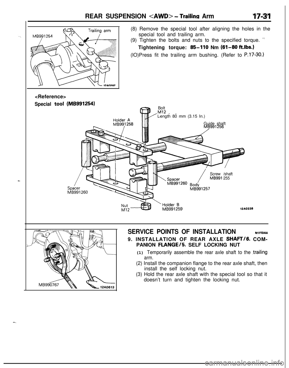
Specialtool(MB9912541(8) Remove the special tool after aligning the holes in the
special tool and trailing arm.
(9) Tighten the bolts and nuts to the specified torque.
“’Tightening torque:
85-110 Nm (81-80 ft.lbs.)(lO)Press fit the trailing arm bushing. (Refer to
P.?7-30.)Bolt
Ml2LI--
ength 80 mm (3.15 In.)
Guide shaft
/Screw /shaft
/MB591 255
12AO338
SERVICE POINTS OF INSTALLATION
NlTlDAA9. INSTALLATION OF REAR AXLE SHAFT/G. COM-
PANION
FLANGE/5. SELF LOCKING NUT
(1) Temporarily assemble the rear axle shaft to the ,trailing
arm.(2) Install the companion flange to the rear axle shaft, then
install the self locking nut.
(3) Hold the rear axle shaft with the special tool so that it
doesn’t turn and tighten the locking nut.
Page 644 of 1216
17-34REAR SUSPENSION
12A0049CUP assemblv
Dud cover
Bracket assembly
1Shock absorber lower bushing
12R0140I
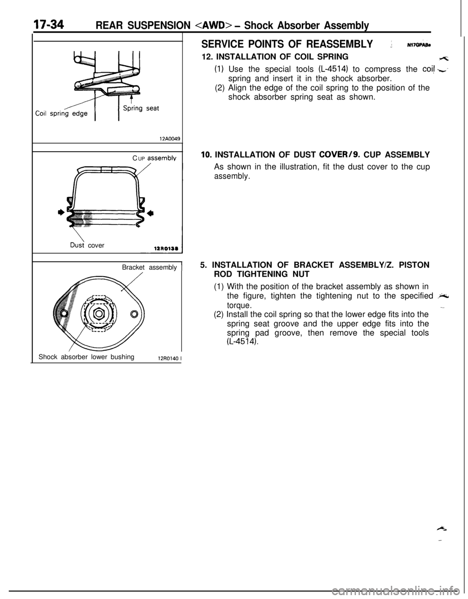
SERVICE POINTS OF REASSEMBLY; N17GPi4te12. INSTALLATION OF COIL SPRING
(1) Use the special tools (L-4514) to compress the coi! zspring and insert it in the shock absorber.
(2) Align the edge of the coil spring to the position of the
shock absorber spring seat as shown.
10. INSTALLATION OF DUST COVER/S. CUP ASSEMBLY
As shown in the illustration, fit the dust cover to the cup
assembly.5. INSTALLATION OF BRACKET ASSEMBLY/Z. PISTON
ROD TIGHTENING NUT
(1) With the position of the bracket assembly as shown in
the figure, tighten the tightening nut to the specified
.%
torque.
-(2) Install the coil spring so that the lower edge fits into the
spring seat groove and the upper edge fits into the
spring pad groove, then remove the special tools
(L-4514).
Page 647 of 1216
-.REAR SUSPENSION
- Stabilizer Bar17-37Clip
ring
12LO217
Jrpose
\12LQ243
Hold with
wrench
12AOlOO
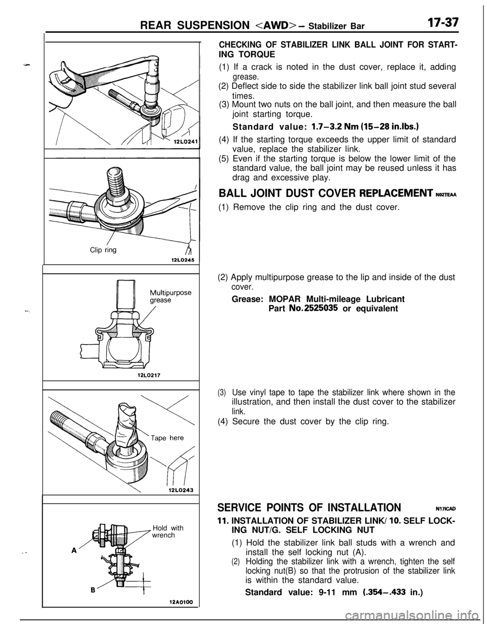
CHECKING OF STABILIZER LINK BALL JOINT FOR START-ING TORQUE
(1) If a crack is noted in the dust cover, replace it, adding
grease.(2) Deflect side to side the stabilizer link ball joint stud several
times.(3) Mount two nuts on the ball joint, and then measure the ball
joint starting torque.
Standard value:
1.7-3.2 Nm (15-28 in.lbs.)(4) If the starting torque exceeds the upper limit of standard
value, replace the stabilizer link.
(5) Even if the starting torque is below the lower limit of the
standard value, the ball joint may be reused unless it has
drag and excessive play.
BALL JOINT DUST COVER REPLACEMENTNozm(1) Remove the clip ring and the dust cover.
(2) Apply multipurpose grease to the lip and inside of the dust
cover.Grease: MOPAR Multi-mileage Lubricant
Part No.2525035 or equivalent
(3)Use vinyl tape to tape the stabilizer link where shown in theillustration, and then install the dust cover to the stabilizer
link.(4) Secure the dust cover by the clip ring.
SERVICE POINTS OF INSTALLATIONNl7ICAO
11. INSTALLATION OF STABILIZER LINK/ 10. SELF LOCK-
ING NUT/G. SELF LOCKING NUT
(1) Hold the stabilizer link ball studs with a wrench and
install the self locking nut (A).
(2)Holding the stabilizer link with a wrench, tighten the self
locking nut(B) so that the protrusion of the stabilizer linkis within the standard value.
Standard value: 9-11 mm
(.354-.433 in.)
Page 649 of 1216
STEERING
CONTENTSNISAA-
MANUAL STEERINGGEAR BOX.................21
POWER STEERINGGEAR BOX...................
28
POWER STEERING
HOSES........................
46
POWER STEERING OIL PUMP....................39
SERVICE ADJUSTMENT PROCEDURES
Steering Angle Check..............................7
Steering Wheel Centering.........................8
Steering Wheel Free Play Check.............:..7Tie Rod End Ball Joint Starting Torque
Check..................................................8Tie Rod End Ball Joint Variation Check
(Shaft direction).....................................7
SERVICE ADJUSTMENT PROCEDURES
< POWER STEERING >.............................
10
Bleeding...............................................13Fluid Level Check...................................
12
Fluid Replacement..................................12
i;,
Oil Pressure Switch Check........................15
Oil Pump Pressure Test...........................14
Stationary Steering Effort Check.................11Steering Angle Check..............................
10
Steering Wheel Centering.........................1 1
Steering Wheel Free Play Check................10Steering Wheel Return to Center Check.......
11Tie Rod End Ball Joint Starting Torque
Check..................................................10Tie Rod End Bail Joint Variation Check
(Shaft direction).....................................10
V-Belt Tension Check..............................12
SPECIAL TOOLS......................................6
SPECIFICATIONS.....................................2;
General Specifications..............................2
Lubricants.............................................5
Sealants and Adhesives............................5
Service Specifications.............‘................2
Torque Specifications,. . . . . . . . . . . . . . . . . ..*..........3
STEERING WHEEL AND SHAFT.................. 16
Page 650 of 1216
19-2STEERING - Specifications
SPECIFICATIONS
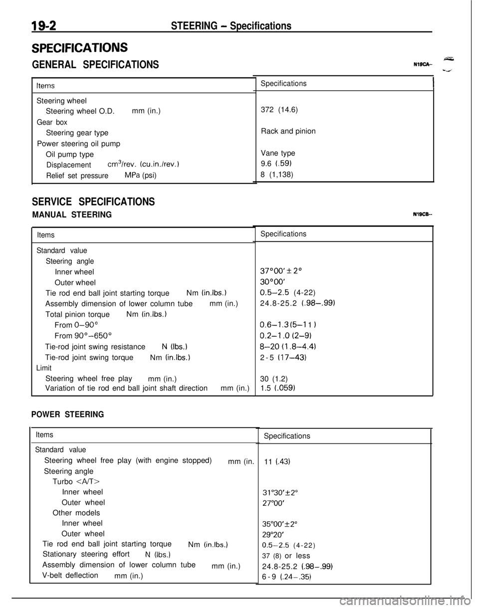
GENERAL SPECIFICATIONS
ItemsSteering wheel
Steering wheel O.D.mm (in.)
Gear boxSteering gear type
Power steering oil pump
Oil pump type
Displacementcm3/rev. (cu.in./rev.)
Relief set pressureMPa (psi)
SERVICE SPECIFICATIONS
MANUAL STEERING
Items
Standard value
Steering angleInner wheel
Outer wheel
Tie rod end ball joint starting torqueNm
(in.lbs.)Assembly dimension of lower column tubemm (in.)
Total pinion torqueNm
(in.lbs.)From
O-90”From
90”-650”Tie-rod joint swing resistance
N (Ibs.)Tie-rod joint swing torque
Nm
(in.lbs.)
LimitSteering wheel free play
mm (in.)
Variation of tie rod end ball joint shaft directionmm (in.)
POWER STEERING
Items
Standard valueSteering wheel free play (with engine stopped)
mm (in.
Steering angle
Turbo
Inner wheel
Outer wheel
Other models
Inner wheel
Outer wheel
Tie rod end ball joint starting torque
Nm
(in.lbs.)Stationary steering effort
N (Ibs.)Assembly dimension of lower column tube
mm (in.)
V-belt deflection
mm (in.)
NlSCA--
Specifications372 (14.6)
Rack and pinion
Vane type
9.6 t.59)
8 (1,138)NlSCB-
Specifications37000’
* 20
3OOOO’
0.5-2.5 (4-22)
24.8-25.2
(.98-,991
0.6-l .3 (5-l 1 I
0.2-l .o (2-9)
8-20 (I .8-4.4)2-5
(17-43)30 (1.2)
1.5 l.059)
Specifications
11
(.43)
31"30'+2"
27"OO'
35"00'f2"
29"20'
0.5-2.5 (4-22)
37 (8) or less
24.8-25.2
(.98-.99)6-9 (.24-.35)
Page 651 of 1216
-
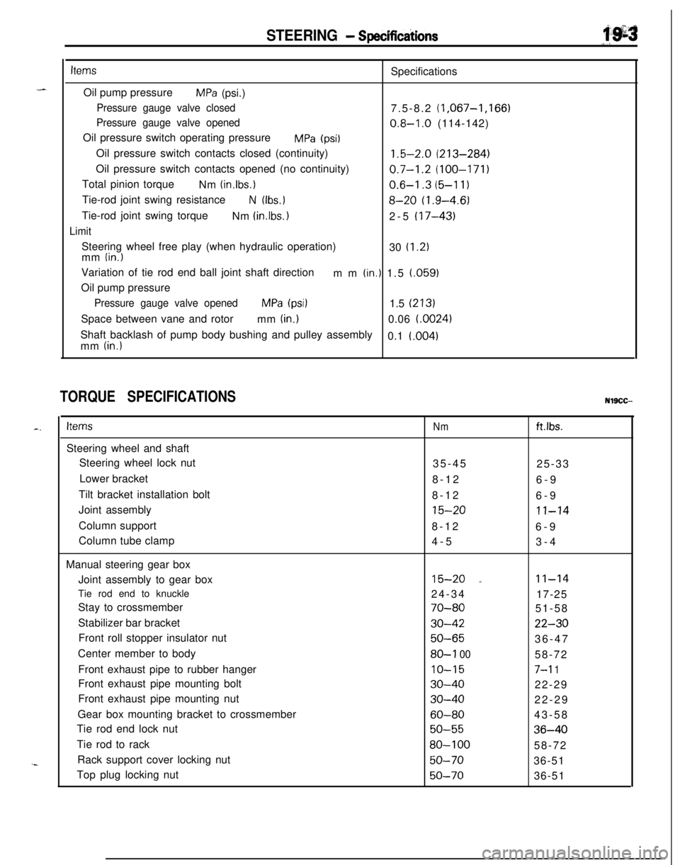
STEERING - Specificdions
i’.g=s
“,.
itemsSpecifications
Oil pump pressure
MPa (psi.)
Pressure gauge valve closed7.5-8.2 (1,067-1,166)
Pressure gauge valve opened0.8-I .O (114-142)
Oil pressure switch operating pressure
MPa (psi1Oil pressure switch contacts closed (continuity)
1.5-2.0 (213-284)Oil pressure switch contacts opened (no continuity)
0.7-1.2 (100-171)Total pinion torque
Nm
(in.lbs.)0.6-I .3 (5-l 1)Tie-rod joint swing resistance
N (Ibs.18-20 (1.9-4.6)Tie-rod joint swing torque
Nm
(in.lbs. 12-5 (17-43)
LimitSteering wheel free play (when hydraulic operation)
30
(1.2)mm (in.)Variation of tie rod end ball joint shaft direction
mm
(in.) 1.5 (.059)
Oil pump pressure
Pressure gauge valve openedMPa (psi)1.5 (213)Space between vane and rotor
mm
(in.)0.06 i.0024)Shaft backlash of pump body bushing and pulley assembly
0.1
i.004)mm (in.)
TORQUE SPECIFICATIONSNlSCC--
c.ItemsSteering wheel and shaft
Steering wheel lock nut
Lower bracket
Tilt bracket installation bolt
Joint assembly
Column support
Column tube clamp
Manual steering gear box
Joint assembly to gear box
Tie rod end to knuckle
Stay to crossmember
Stabilizer bar bracket
Front roll stopper insulator nut
Center member to body
Front exhaust pipe to rubber hanger
Front exhaust pipe mounting bolt
Front exhaust pipe mounting nut
Gear box mounting bracket to crossmember
Tie rod end lock nut
Tie rod to rack
Rack support cover locking nut
Top plug locking nutNmftlbs.35-45
25-33
8-12
6-9
8-12
6-9
15-2011-148-12
6-9
4-5
3-4
15-20 a11-1424-34
17-25
70-8051-58
30-4222-30
50-6536-47
80-l 0058-72
IO-157-l 1
30-4022-29
30-4022-29
60-8043-58
50-5536-40
80-10058-72
50-7036-51
50-7036-51
Page 655 of 1216
STEERING - Special Tools/Service Adjustment Procedures
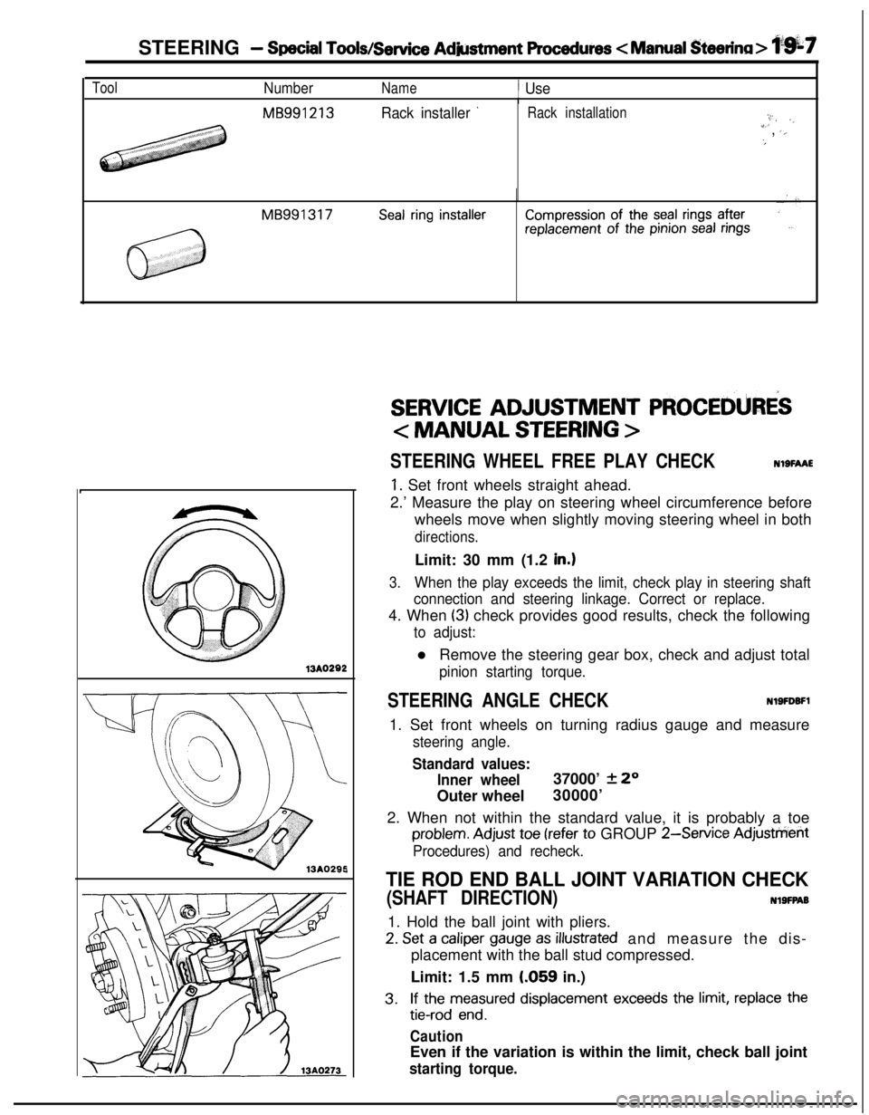
ToolNumberName1 UseI
MB991213Rack installer ’Rack installation:,.I/ ._i’, ‘,‘#
MB991317Seal ring installerCompression of the seal rings afterreplacement of the pinion seal rings13A0282
,
SERVICE ADJUSTMENT PROCEDURiS
< MANUAL STEERING >
STEERING WHEEL FREE PLAY CHECKNOSFAAE
1. Set front wheels straight ahead.
2.’ Measure the play on steering wheel circumference before
wheels move when slightly moving steering wheel in both
directions.Limit: 30 mm (1.2
in.1
3.When the play exceeds the limit, check play in steering shaft
connection and steering linkage. Correct or replace.4. When
(3) check provides good results, check the following
to adjust:l Remove the steering gear box, check and adjust total
pinion starting torque.
STEERING ANGLE CHECKNlSFDBFl1. Set front wheels on turning radius gauge and measure
steering angle.
Standard values:
Inner wheel37000’
2 20
Outer wheel30000’
2. When not within the standard value, it is probably a toe
problem. Adjust toe (refer to GROUP 2-Service Adjusttierit
Procedures) and recheck.
TIE ROD END BALL JOINT VARIATION CHECK
(SHAFT DIRECTION)NlSFPAB1. Hold the ball joint with pliers.
2. Set a caliper gauge as illustrated and measure the dis-
placement with the ball stud compressed.
Limit: 1.5 mm
LO59 in.)
3.If the measured displacement exceeds the limit, replace the
tie-rod end.
CautionEven if the variation is within the limit, check ball joint
starting torque.