torque MITSUBISHI ECLIPSE 1991 Manual PDF
[x] Cancel search | Manufacturer: MITSUBISHI, Model Year: 1991, Model line: ECLIPSE, Model: MITSUBISHI ECLIPSE 1991Pages: 1216, PDF Size: 67.42 MB
Page 597 of 1216
, d-a:-;._‘PROPELLER
=. ’SHAFT
CONTENTSNlBAA-
PROPELLER SHAFT........................................4Lubricants......................................................3
2
SPECIAL TOOLS3ServiceSpecifications.................................................................................
TorqueSpecifications...................................2
SPECIFICATIONS.............................................2
TROUBLESHOOTING......................................3
General
Specifications..................................21
Page 598 of 1216
16-2PROPELLER SHAFT - Specifications
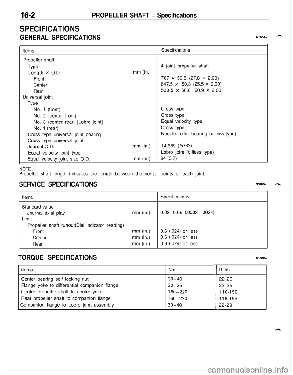
SPECIFICATIONS
GENERAL SPECIFICATIONSNWCA--
ItemsPropeller shaft
TypeLength
x O.D.
Front
Center
RearUniversal joint
TypeSpecifications
4 joint propeller shaft
mm (in.)
707
x 50.8 (27.8 x 2.00)
647.5
x. 50.8 (25.5 x 2.00)
530.5
x 50.8 (20.9 x 2.00)
No.
1 (front)
No. 2 (center front)
No. 3 (center rear) [Lobro joint]
No. 4 (rear)
Cross type universal joint bearing
Cross type universal joint
Journal O.D.
Equal velocity joint type
Equal velocity joint size O.D.mm (in.)
mm (in.)Cross type
Cross type
Equal velocity type
Cross type
Needle roller bearing
(oilless type)
14.689
(.5783)Lobro joint
(oilless type)
94 (3.7)
NOTEPropeller shaft length indicates the length between the center points of each joint.
SERVICE SPECIFICATIONSNWCB-
ItemsSpecifications
Standard value
Journal axial playmm (in.)
0.02-0.06 (.0008-.0024)
Limit
Propeller shaft
runout(Dial indicator reading)
Frontmm (in.)
0.6 (.024) or less
Centermm (in.)0.6 (.024) or less
Rearmm (in.)0.6 (.024) or less
TORQUE SPECIFICATIONSNlBCC--
ItemsNmCenter bearing self locking nut
30-40Flange yoke to differential companion flange
30-35Center propeller shaft to center yoke
160-220Rear propeller shaft to companion flange
160-220Companion flange to Lobro joint assembly
30-40tft.lbs.
22-29
22-25
116-159
116-159
22-29
Page 609 of 1216
PROPELLER SHAFT - Propeller Shaft
NOTEFace the side onto which the center bearing bracket
mating mark is placed and the dust seal is
in,stalled to
the side of the center propeller shaft and
rear.propeller
10X0032
1 OY607
shaft.
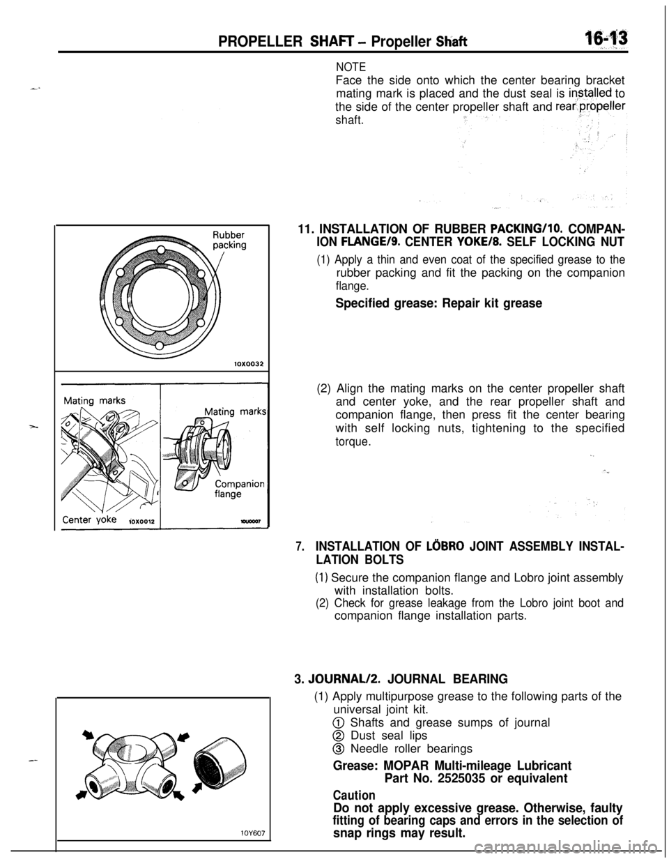
11. INSTALLATION OF RUBBER PACKING/lo. COMPAN-
ION FLANGE/S. CENTER YOKE/8. SELF LOCKING NUT
(1) Apply a thin and even coat of the specified grease to therubber packing and fit the packing on the companion
flange.
Specified grease: Repair kit grease(2) Align the mating marks on the center propeller shaft
and center yoke, and the rear propeller shaft and
companion flange, then press fit the center bearing
with self locking nuts, tightening to the specified
torque.
,.
7.INSTALLATION OF LOBRO JOINT ASSEMBLY INSTAL-
LATION BOLTS
(1) Secure the companion flange and Lobro joint assembly
with installation bolts.
(2) Check for grease leakage from the Lobro joint boot andcompanion flange installation parts.
3. JOURNAL/2. JOURNAL BEARING(1) Apply multipurpose grease to the following parts of the
universal joint kit.
@ Shafts and grease sumps of journal
@ Dust seal lips
@ Needle roller bearings
Grease: MOPAR Multi-mileage Lubricant
Part No. 2525035 or equivalent
Caution
Do not apply excessive grease. Otherwise, faulty
fitting of bearing caps and errors in the selection of
snap rings may result.
Page 611 of 1216
1 pq
,s I’
:
REAR
SUSPENSION
LATERAL ROD.................................................11
REAR AXLE HUB............................................14
REARSUSPENSIONASSEMBLY..................5
SERVICE ADJUSTMENT PROCEDURES.......3Rear Hub Rotary-Sliding Resistance
(Torque)Adjustment.....................................4Rear Wheel Alignment Inspection
...............3Wheel Bearing End Play Adjustment
..........3
SHOCKABSORBERASSEMBLY...................8
SPECIAL TOOL................................................3
SPECIFICATIONS.............................................2
GeneralSpecifications..................................2
ServiceSpecifications...................................2Torque Specifications
...................................2
TORSION AXLE AND ARM ASSEMBLY......12
TROUBLESHOOTING......................................3
REARSUSPENSIONASSEMBLY . . . . . . . . . . . . . . . . . .21
SHOCK ABSORBER ASSEMBLY...................32
SERVICE ADJUSTMENT PROCEDURES.......20Rear WheelAlignment
Inspection................20
SPECIAL TOOLS.............................................18
SPECIFICATIONS.............................................16
GeneralSpecifications..................................16
ServiceSpecifications...................................16LTorqueSpecifications...................................17
Lubricant.......................................................17
STABILIZER BAR. . . . . . . . . . . . . . . . . . . . . . . . . . . . . . . . . . . . . . . . . . . . .35
TRAILING ARM. . . . . . . . . . . . . . . . . . . . . . . . . . . . . . . . . . . . . . . . . . . . . . .28
TROUBLESHOOTING......................................19
UPPER AND LOWER ARM............................25
CONTENTSN17AA-
Page 612 of 1216
17-2REAR SUSPENSION
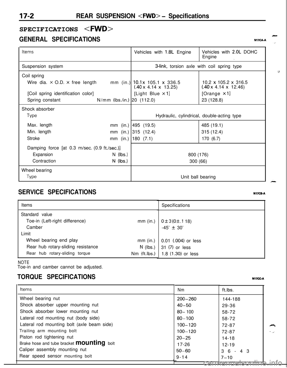
GENERAL SPECIFICATIONS
LN17CAA
ItemsVehicles with 1.8L EngineVehicles with 2.0L DOHC
Engine
jSuspension system
3-link, torsion axle with coil spring type
Coil spring
Wire dia.
x O.D. x free length
mm (in.) 10.1 x 105.1 x 336.510.2 x 105.2 x 316.5
(40 x 4.14 x 13.25)(40 x 4.14 x 12.46)
[Coil spring identification color]
[Light Blue
x 11[Orange x 11Spring constant
N/mm
(Ibs./in.) 20 (112.0)23 (128.8)
Shock absorber
TypeHydraulic, cylindrical, double-acting type
Max. length
mm (in.) 495 (19.5)485 (19.1)
Min. length
mm (in.) 315 (12.4)315 (12.4)
Strokemm (in.) 180 (7.1)170 (6.7)Damping force [at 0.3 m/set. (0.9
ft./set.)]
ExpansionN (Ibs.)800 (176)
ContractionN (Ibs.)300 (66)
Wheel bearing
TypeUnit ball bearing
SERVICE SPECIFICATIONS
Items
Standard valueToe-in (Left-right difference)
Camber
LimitWheel bearing end play
Rear hub rotary-sliding resistance
Rear hub rotary-sliding torque
NOTEToe-in and camber cannot be adjusted.mm (in.)
mm (in.)
N (Ibs.)
Nm
(ftlbs.)
TORQUE SPECIFICATIONS
Specifications
0+3 (Of.1 18)
-45’
f 30’
0.01 (004) or less
31
(7) or less
1.8
(1.30) or lessNI’ICB-A
ItemsNmft.lbs.
Wheel bearing nut
Shock absorber upper mounting nut
Shock absorber lower mounting nut
Lateral rod mounting nut (body side)
Lateral rod mounting bolt (axle beam side)
Trailing arm mounting bolt
Piston rod tightening nut
Brake hose and tube bracket mounting bolt
Caliper assembly mounting nut
Rear speed sensor mounting bolt
200-260
40-50
80- 100
80-100
100-120
100-120
20-2517-26
50-609-14144-188
29-36
58-72
58-72
72-87
72-87
14-18
12-19
36-43
I7-10
Nl7CGA
Page 613 of 1216
Special Tools/Troubleshooting/REAR SUSPENSION
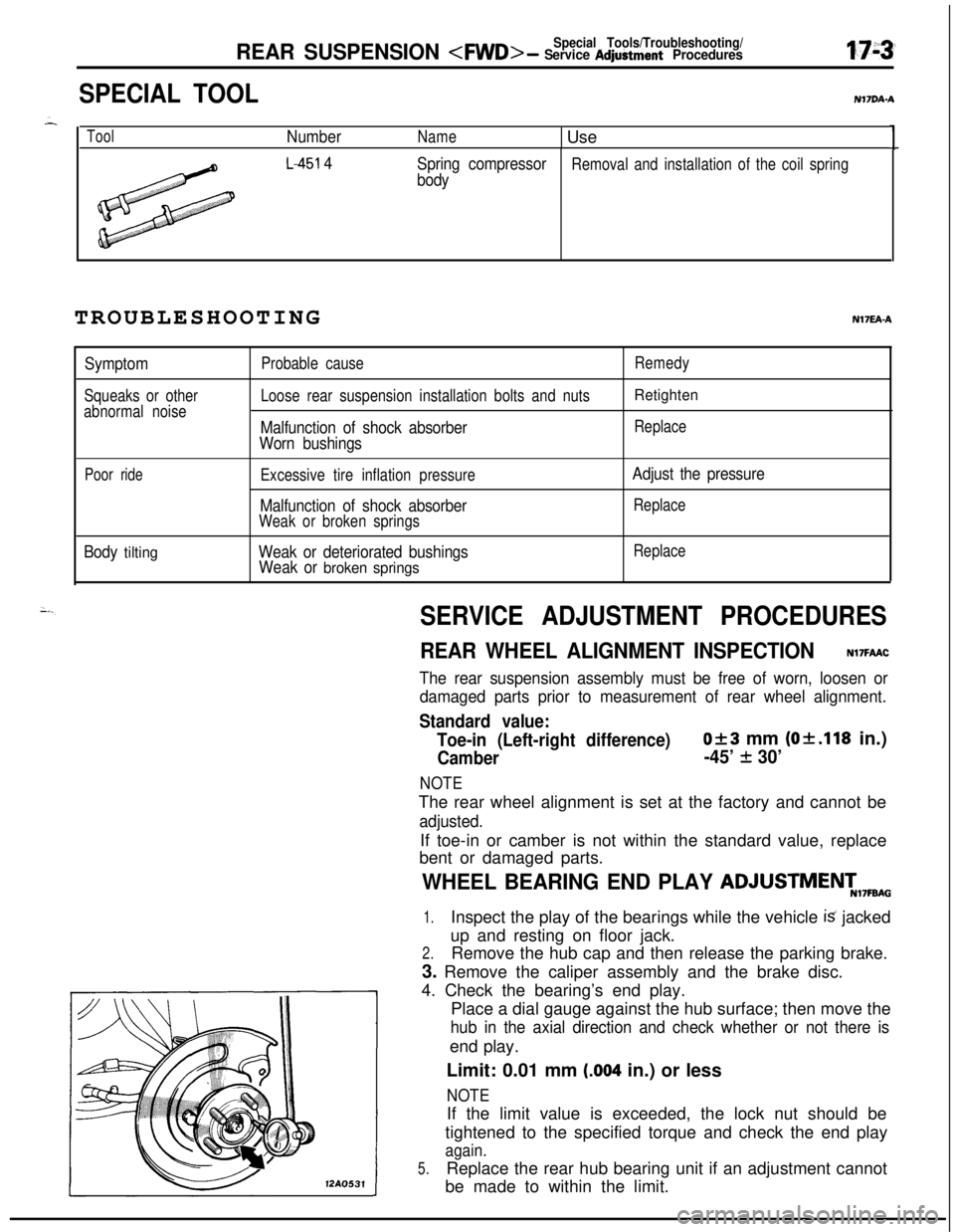
SPECIAL TOOLN17DA.A
ToolNumberName1 Use1
L-451 4
Spring compressorRemoval and installation of the coil spring
bodyTROUBLESHOOTINGNI’IEA-A
Symptom
Squeaks or other
abnormal noiseProbable cause
Loose rear suspension installation bolts and nuts
Malfunction of shock absorber
Worn bushings
Remedy
Retighten
Replace
Poor rideExcessive tire inflation pressure
Malfunction of shock absorberWeak or broken springs
Adjust the pressure
Replace
Body tiltingWeak or deteriorated bushings
Weak or broken springs
Replace
SERVICE ADJUSTMENT PROCEDURES
REAR WHEEL ALIGNMENT INSPECTIONN17FAAC
The rear suspension assembly must be free of worn, loosen or
damaged parts prior to measurement of rear wheel alignment.
Standard value:
Toe-in (Left-right difference)
Of3 mm (Of.118 in.)
Camber-45’ + 30’
NOTEThe rear wheel alignment is set at the factory and cannot be
adjusted.If toe-in or camber is not within the standard value, replace
bent or damaged parts.
WHEEL BEARING END PLAY ADJUSTMENT,7FBA0
1.Inspect the play of the bearings while the vehicle is jacked
up and resting on floor jack.
2.Remove the hub cap and then release the parking brake.
3. Remove the caliper assembly and the brake disc.
4. Check the bearing’s end play.
Place a dial gauge against the hub surface; then move the
hub in the axial direction and check whether or not there isend play.
Limit: 0.01 mm
(.004 in.) or less
NOTE12AO531If the limit value is exceeded, the lock nut should be
tightened to the specified torque and check the end play
again.
5.Replace the rear hub bearing unit if an adjustment cannot
be made to within the limit.
Page 614 of 1216

17-4REAR SUSPENSION
12A0533
3REAR HUB ROTARY-SLIDING
RESISTANCE
(TORQUE) ADJUSTMENTN17FCAC -
1.Inspect the play of the bearings while the vehicle is jacked.
up and resting on floor jack.
2. Release the parking brake.
3. Remove the caliper assembly and the brake disc.
4. After turnina the hub a few times to seat the bearing,
attach a spriig balance to the hub bolt, and, pulling at a 9@angle from the hub bolt, measure to determine whether or
not the rotary-sliding resistance of the rear hub (the
rotary-sliding torque of the rear hub) is the standard value.
Limit:
Rear hub rotary-sliding resistance
31N (7 Ibs.) or less
Rear hub rotary-sliding torque1.8 Nm (1.30
ft.lbs.) or less
NOTEIf the limit value is exceed, loosen the nut and then tighten
it to the specified torque, and check the rear hub
rotary-sliding torque again.
5. Replace the rear hub bearing unit if an adjustment cannot
+.be made to within the limit.
A
Page 615 of 1216
REAR SUSPENSION
REAR SUSPENSION ASSEMBLYu
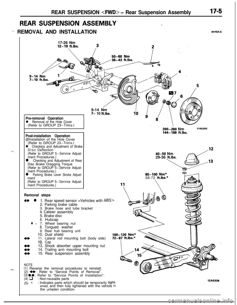
-%. REMOVAL AND INSTALLATIONN17GAA
---i
--..17-26 Nm12-19
ft.lbs.9-14 Nm
7- 10 ft.lbs.
Pre-removal Operationl Removal of the Hole Cover(Refer to GROUP 23-Trims.)
Post-installation Operation@Installation of the Hole Cover
(Refer to GROUP
23-Trims.)l Checking and Adiustment of BrakeDisc De‘ilection ’(Refer to GROUP 5-Service Adjust-ment Procedures.)
l Checking and Adjustment of RearDisc Brake Dragging Torque
(Refer to GROUP &Service Adjust-ment Procedures.)
l Parking Brake Lever Stroke Adjust-ment
(Refer to GROUP 5-Service Adjust-ment Procedures.)
Removal steps
W l1. Rear speed sensor
2. Parking brake cable3. Brake hose and tube bracket
4.
Calioer assemblv
200-280 Nm144-168 ftlbs.
llAO293
40-50 Nm
29-36 ltlbs.80-100
Nm*58-72 ft.lbs.*5. Brake disc
’6.Hubcapl +7. Wheel bearing nut8.Tongued washer9. Rear hub bearing unit
10.Dust shield
4*11. Lateral rod mounting bolt (body side)12.Cap
t:
13. Shock absorber upper mounting nut
14. Trailing arm mounting bolt
4*15. Rear suspension assembly
NOTE(I) Reverse the removal procedures to reinstall.
(2) +e : Refer to “Service Points of Removal”.(31 ~~ : Refer to “Service Points of Installation”.
(4) q : Non-reusable parts
(5)
*: Indicates parts which should be temporarily tight-ened, and then fully tightened with the vehicle Inthe unladen condition.12AO336
Page 620 of 1216
L
)il spri
12A0049
REAR SUSPENSION
SERVICE POINTS OF REASSEMBLYNl7QPA2
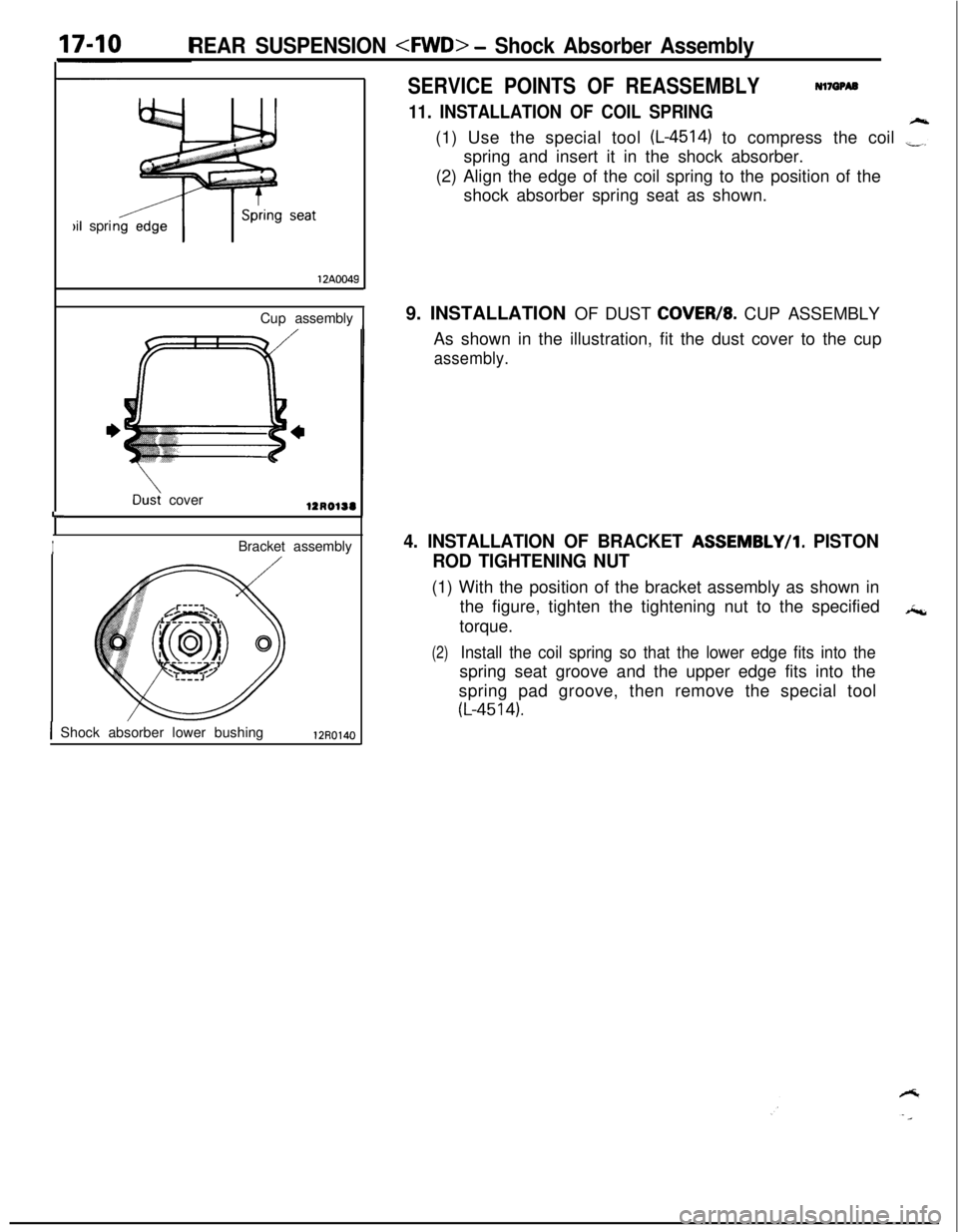
11. INSTALLATION OF COIL SPRING(1) Use the special tool
(L-4514) to compress the coil ,“3”spring and insert it in the shock absorber.
(2) Align the edge of the coil spring to the position of the
shock absorber spring seat as shown.
Cup assembly
1
Dd cover
IBracket assembly
1 Shock absorber lower bushing12R01409. INSTALLATION OF DUST
COVEW8. CUP ASSEMBLY
As shown in the illustration, fit the dust cover to the cup
assembly.
4. INSTALLATION OF BRACKET ASSEMBLY/l. PISTON
ROD TIGHTENING NUT(1) With the position of the bracket assembly as shown in
the figure, tighten the tightening nut to the specified*c,
torque.
(2)Install the coil spring so that the lower edge fits into thespring seat groove and the upper edge fits into the
spring pad groove, then remove the special tool
(L-4514).
Page 622 of 1216
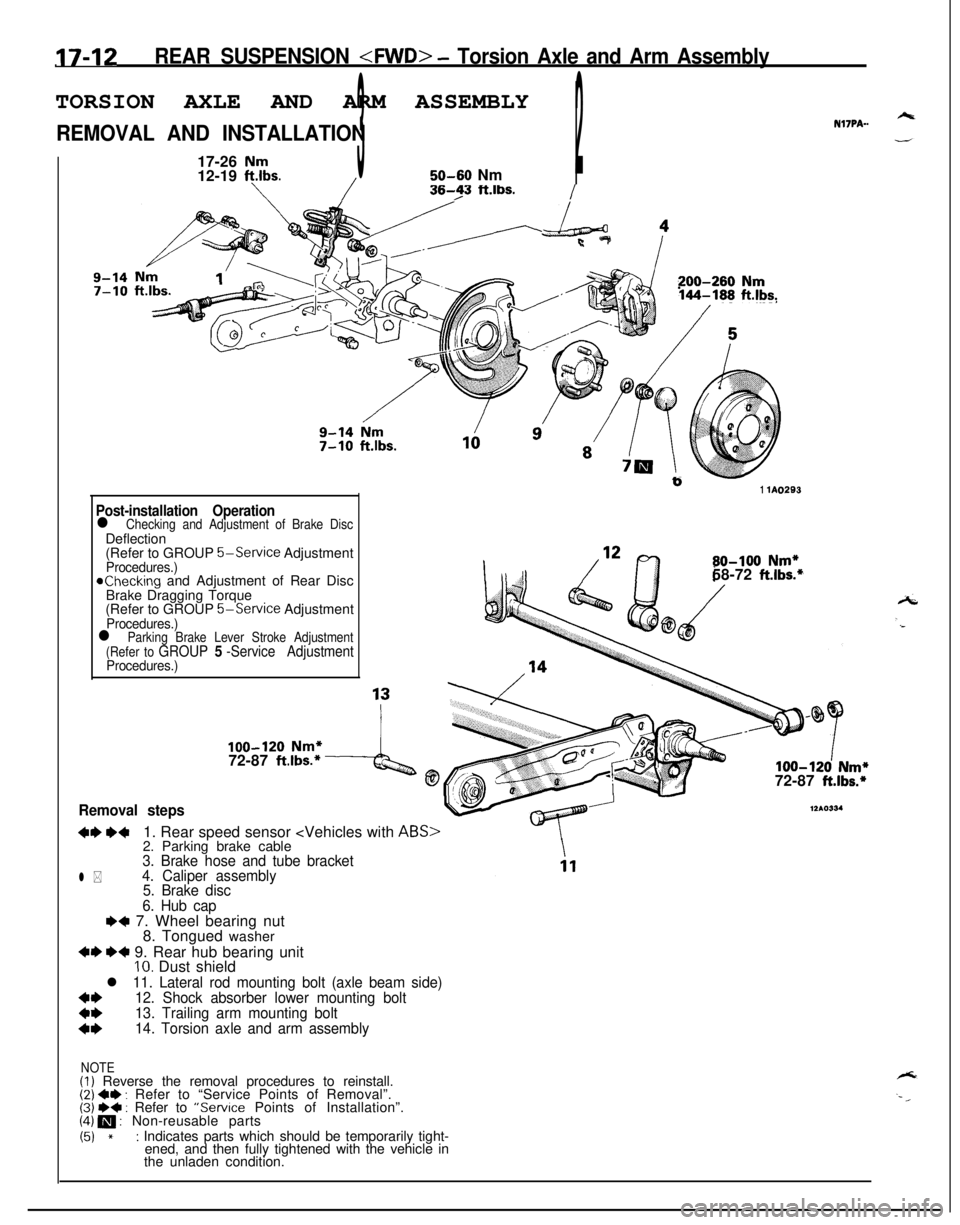
17-12REAR SUSPENSION
REMOVAL AND INSTALLATIONNl’IPA-.
17-26
Nm12-19 ft.lbs.350-60 Nm2/I
/36-23 ft.lbs./
Nm1’200-260 Nm144-188 ft.lbs.
b1 lA0293
Post-installation Operationl Checking and Adjustment of Brake DiscDeflection
(Refer to GROUP
5-Service AdjustmentProcedures.)achecking and Adjustment of Rear Disc
Brake Dragging Torque
(Refer to GROUP
5-Service AdjustmentProcedures.)
80-100 Nm*58-72 ft.lbs.*
l Parking Brake Lever Stroke Adjustment
(Refer to GROUP 5 -Service AdjustmentProcedures.)
100-120 Nm*72-87 ft.lbs.*4@100-120 Nm*72-87 ft.lbs.*
Removal steps
+I) ++1. Rear speed sensor
12*0334
l *
3. Brake hose and tube bracket
4. Caliper assembly
5. Brake disc
6. Hub cap
e+ 7. Wheel bearing nut
8. Tongued washer
+I) *+ 9. Rear hub bearing unitIO. Dust shield
l 11. Lateral rod mounting bolt (axle beam side)
*I)12. Shock absorber lower mounting bolt
13. Trailing arm mounting bolt
14. Torsion axle and arm assembly
NOTE(I) Reverse the removal procedures to reinstall.(2) ~~ : Refer to “Service Points of Removal”.(3j W+ : Refer to “Service Points of Installation”.(4) m : Non-reusable parts
(51 *: Indicates parts which should be temporarily tight-
ened, and then fully tightened with the vehicle in
the unladen condition.