light MITSUBISHI ECLIPSE 1991 Service Manual
[x] Cancel search | Manufacturer: MITSUBISHI, Model Year: 1991, Model line: ECLIPSE, Model: MITSUBISHI ECLIPSE 1991Pages: 1216, PDF Size: 67.42 MB
Page 1064 of 1216
23-20BODY - Troubleshooting
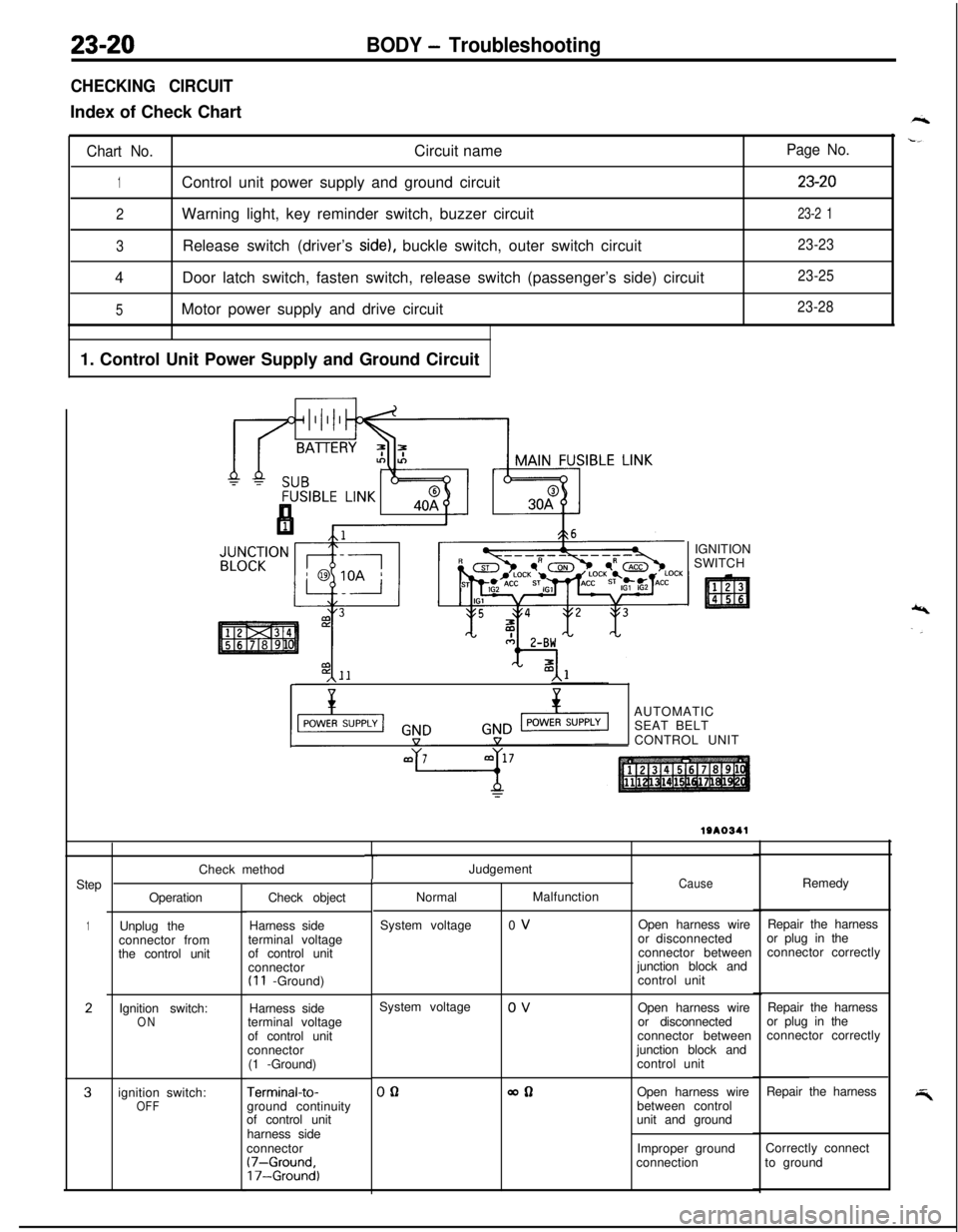
CHECKING CIRCUITIndex of Check Chart
Chart No.Circuit name
1Control unit power supply and ground circuit
2Warning light, key reminder switch, buzzer circuit
3Release switch (driver’s side), buckle switch, outer switch circuit
4Door latch switch, fasten switch, release switch (passenger’s side) circuit
5Motor power supply and drive circuit
1. Control Unit Power Supply and Ground Circuit
Page No.
23-20
23-2 1
23-23
23-25
23-28IGNITION
SWITCH
,\--AUTOMATIC
SEAT BELT
CONTROL UNIT
Step
1
2
3Check method
Operation
Unplug the
connector from
the control unit
Ignition switch:
ONignition switch:
OFFCheck object
Harness side
terminal voltage
of control unit
connector
(I 1 -Ground)
Harness side
terminal voltage
of control unit
connector
(1 -Ground)
Terminal-to-ground continuity
of control unit
harness side
connector
(7-Ground,17-Ground)
TJudgement
NormalMalfunction
System voltage0 VCauseOpen harness wire
or disconnected
connector between
junction block and
control unitRemedy
Repair the harness
or plug in the
connector correctly
System voltage
0 V
Open harness wire
or disconnected
connector between
junction block and
control unitRepair the harness
or plug in the
connector correctly
00allOpen harness wire
between control
unit and groundRepair the harness
Improper groundCorrectly connect
connectionto ground
Page 1065 of 1216
BODY - Troubleshooting23-21
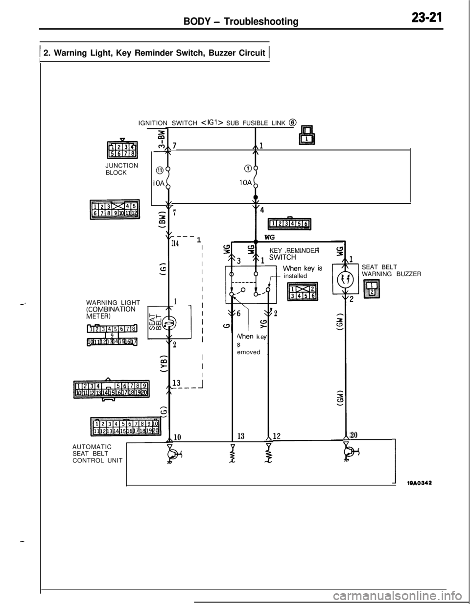
1 2. Warning Light, Key Reminder Switch, Buzzer Circuit 1IIJUNCTION
BLOCK
WARNING LIGHT
gCTy4;NATION
c-7,,7L,,l7,/\
00IOA
IOA
2:y47
.---
141I
I
I
I
I
I
1I
3
2
11
I
I
I13
-I_---
10IGNITION SWITCH
SEAT BELT
CONTROL UNIT
t
11 WG
KEY REMINDER
6
\IL!>
Nhen ke
8emoved
13
+ installed
J
2
1SEAT BELT
WARNING BUZZER
20
w
IIem
Page 1066 of 1216
23-22BODY - TroubleshootingCheck method
StepOperation
Check object
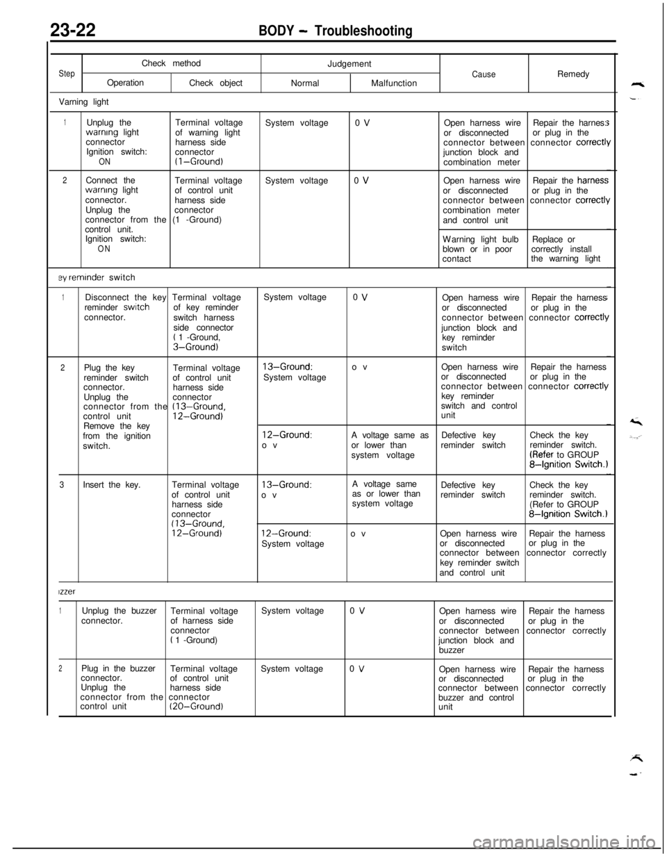
Varning lightJudgementCauseRemedy
NormalMalfunction
1Unplug theTerminal voltagewarnrng light
of warning light
connector
harness side
Ignition switch:
connector
ON(I-Ground)
2Connect the
Terminal voltagewarnrng light
of control unit
connector.
harness side
Unplug theconnector
connector from the (1 -Ground)
control unit.
Ignition switch:
ON
ey reminder switchSystem voltage
System voltage0 V
0 VOpen harness wireRepair the harnes:
or disconnectedor plug in the
connector between connector
correct1junction block and
combination meter
Open harness wireRepair the harries:
or disconnectedor plug in the
connector between connector
correctl!combination meter
and control unit
Warning light bulbReplace or
blown or in poorcorrectly install
contactthe warning light
1Disconnect the key Terminal voltageSystem voltage0 VOpen harness wireRepair the harness
reminder switchof key reminder
or disconnectedor plug in the
connector.
switch harnessconnector between connector
correct11side connector
junction block and
t 1 -Ground,
key reminderS-Ground)switch
2Plug the key
Terminal voltage13-Ground:ovOpen harness wireRepair the harness
reminder switchof control unitSystem voltageor disconnectedor plug in the
connector.
harness sideconnector between connector
correct11Unplug theconnectorkey reminder
connector from the
(13-Ground,switch and control
control unit12-Ground)unit
Remove the key
from the ignition
12-Ground:A voltage same asDefective keyCheck the key
switch.ovor lower thanreminder switchreminder switch.
system voltage(Refer to GROUP
84gnition Switch.1
3Insert the key.Terminal voltage
13-Ground:A voltage same
as or lower thanDefective keyCheck the key
of control unit
ovreminder switchreminder switch.
harness sidesystem voltage
(Refer to GROUP
connector
84gnition Switch.1(13-Ground,12-Ground)12-Ground:ovOpen harness wireRepair the harness
System voltageor disconnectedor plug in the
connector between connector correctly
key reminder switch
and control unit
lzzer
1Unplug the buzzer
Terminal voltageSystem voltage0 VOpen harness wireRepair the harness
connector.of harness side
or disconnectedor plug in the
connector
connector between connector correctly
t 1 -Ground)
junction block and
buzzer
2Plug in the buzzer
Terminal voltageSystem voltage0 VOpen harness wireRepair the harness
connector.
of control unit
or disconnectedor plug in the
Unplug the
harness side
connector between connector correctly
connector from the connector
buzzer and control
control unit
(20-Ground)unit
Page 1073 of 1216
.-
BODY - Troubleshooting
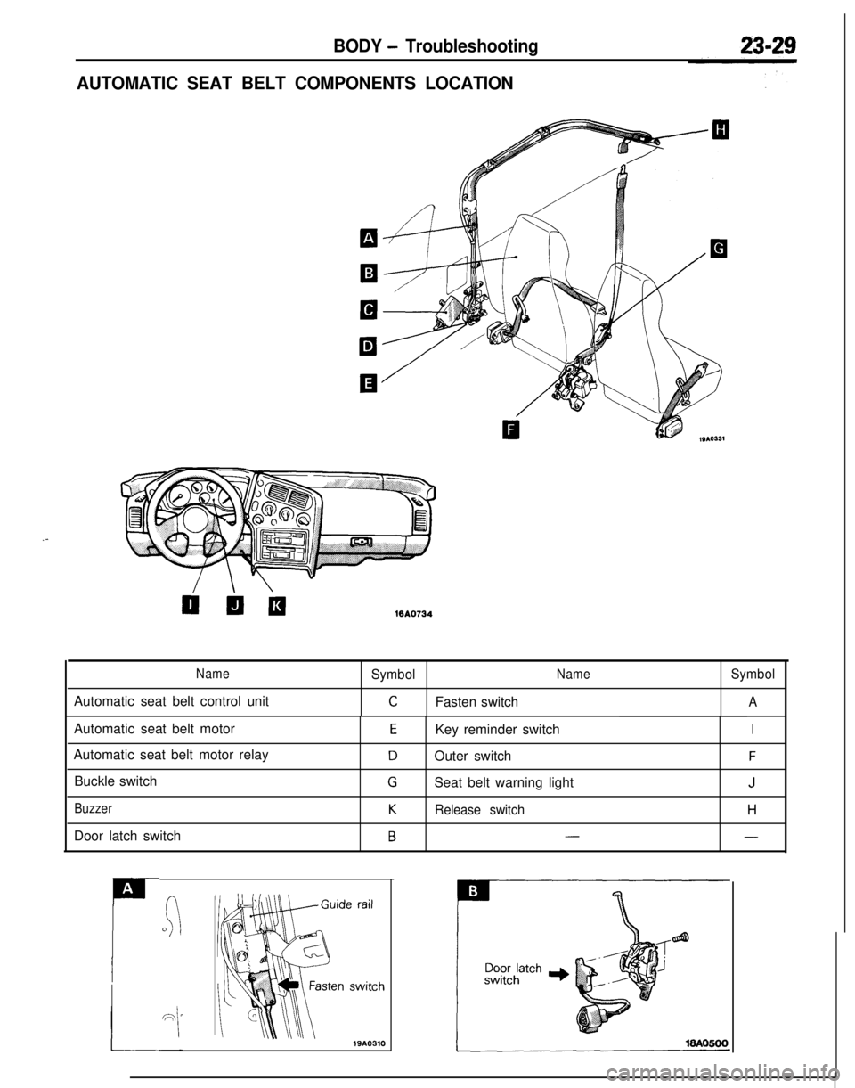
AUTOMATIC SEAT BELT COMPONENTS LOCATION
WA0734
NameSymbolNameSymbolAutomatic seat belt control unit
CFasten switchAAutomatic seat belt motor
Automatic seat belt motor relay
Buckle switch
BuzzerDoor latch switch
EKey reminder switchI
DOuter switchF
GSeat belt warning lightJ
KRelease switchH
B--
A
P
(:0
Page 1078 of 1216
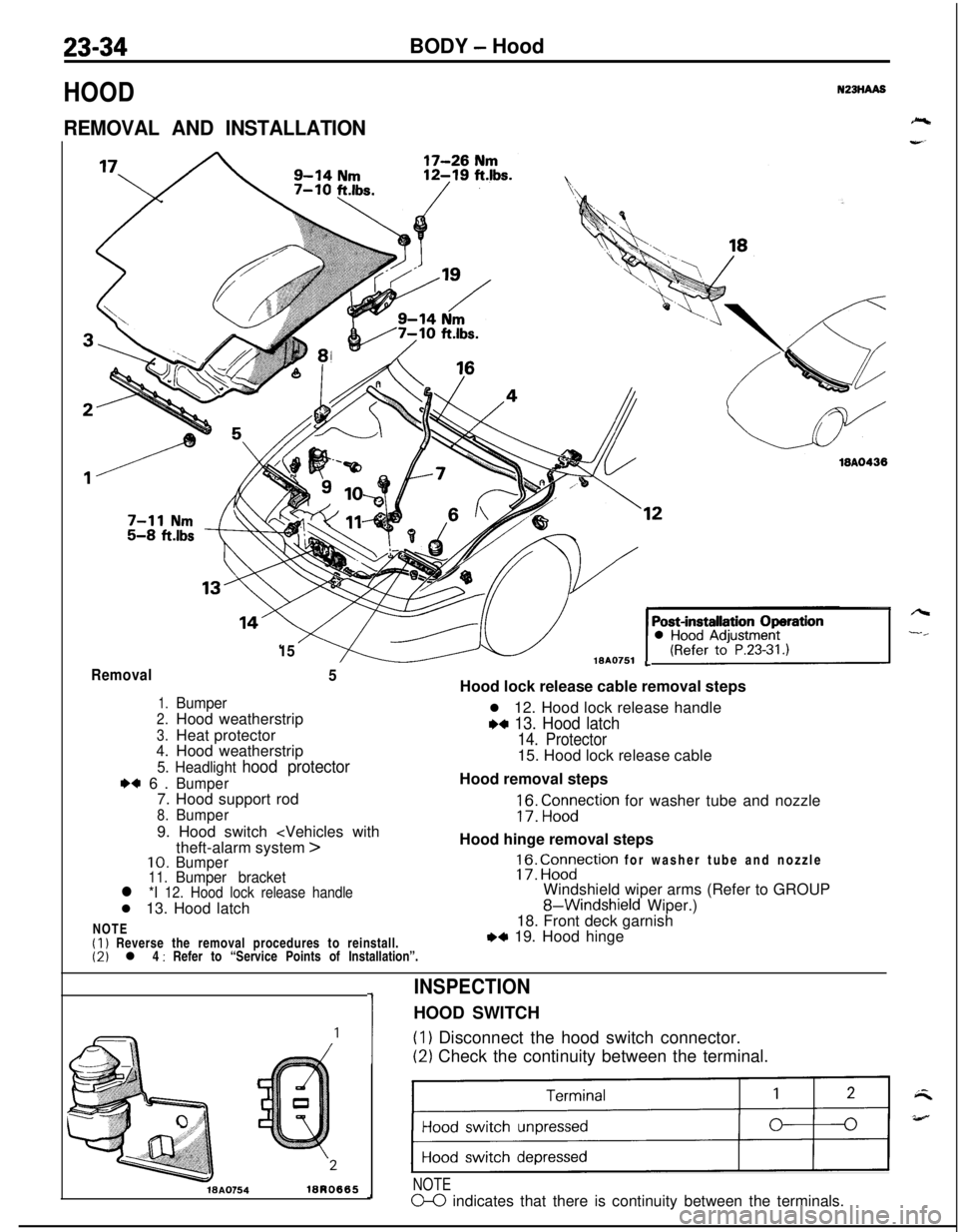
23-34BODY - Hood
HOOD
REMOVAL AND INSTALLATION
N23HAA8
1518AO751
18A0438
LRemoval5
1.Bumper
2.Hood weatherstrip
3.Heat protector4.Hood weatherstrip
5. Headlight hood protector
I)+ 6.Bumper7. Hood support rod
8.Bumper9. Hood switch
>10.Bumper11.Bumper bracketl *I 12. Hood lock release handlel 13. Hood latch
NOTE
(1) Reverse the removal procedures to reinstall.(2) l 4 : Refer to “Service Points of Installation”.Hood lock release cable removal steps
l 12. Hood lock release handle
w 13. Hood latch
14. Protector15. Hood lock release cable
Hood removal steps
;f3: “,;n,yction for washer tube and nozzle
Hood hinge removal steps
17: ig?ction for washer tube and nozzle
Windshield wiper arms (Refer to GROUP
8-Windshield Wiper.)
18. Front deck garnish
,*I 19. Hood hinge
1
INSPECTIONHOOD SWITCH(I
1 Disconnect the hood switch connector.
(2) Check the continuity between the terminal.
WA0754lBRO665
)
NOTE
m indicates that there is continuity between the terminals.
Page 1083 of 1216
BODY - Front Bumper
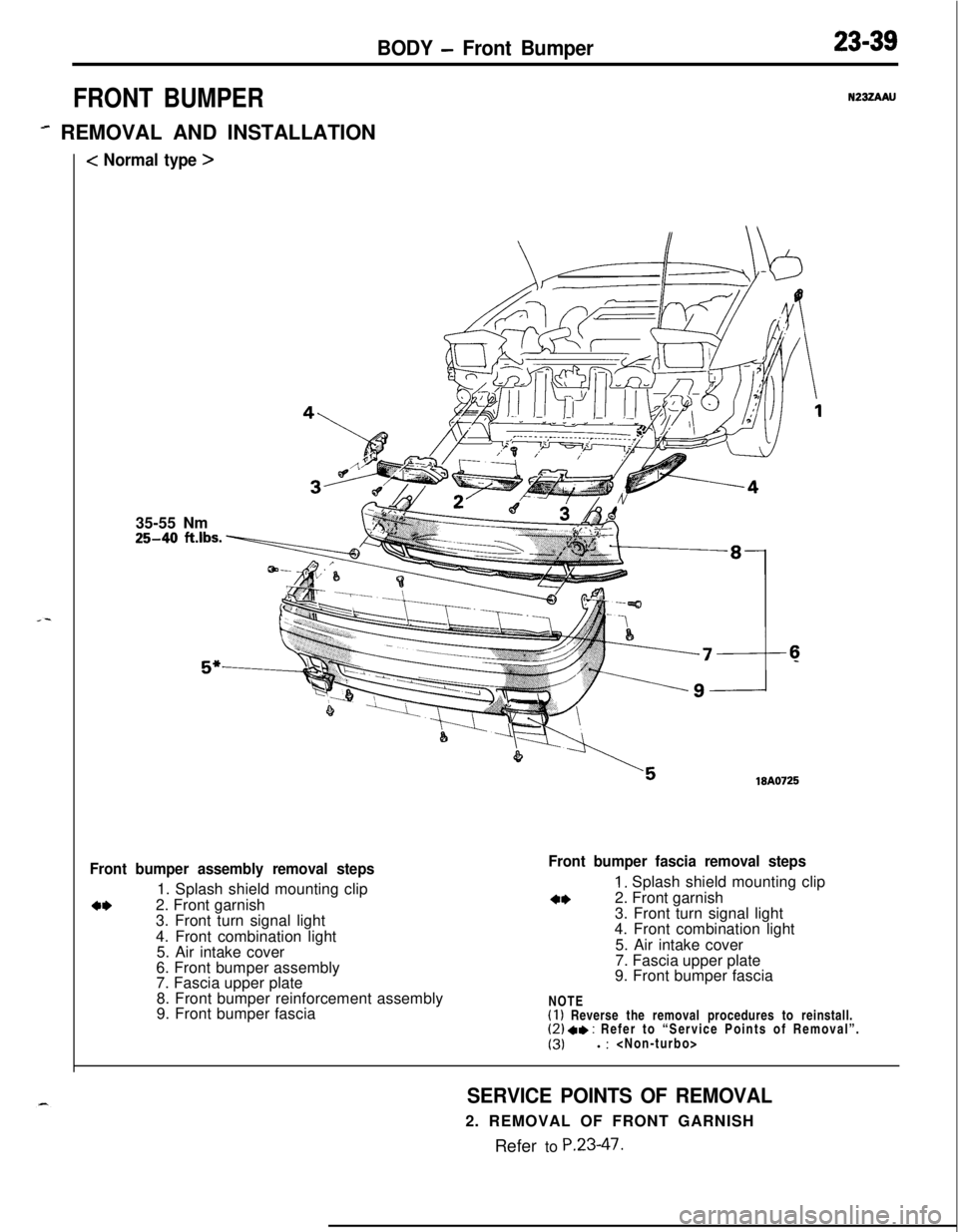
FRONT BUMPER
- REMOVAL AND INSTALLATION
< Normal type >
23-39
N232AAU35-55 Nm25-40
ft.lbs.
”18A0725
Front bumper assembly removal steps1. Splash shield mounting clip
a*2. Front garnish
3. Front turn signal light
4. Front combination light
5. Air intake cover
6. Front bumper assembly
7. Fascia upper plate
8. Front bumper reinforcement assembly
9. Front bumper fascia
Front bumper fascia removal steps
1. Splash shield mounting clip
**2. Front garnish
3. Front turn signal light
4. Front combination light
5. Air intake cover
7. Fascia upper plate
9. Front bumper fascia
NOTE
(I 1 Reverse the removal procedures to reinstall.(2) 4, : Refer to “Service Points of Removal”.
(3)l :
SERVICE POINTS OF REMOVAL2. REMOVAL OF FRONT GARNISH
Refer to
P.23-47.
Page 1084 of 1216
23-40BODY - Front Bumper
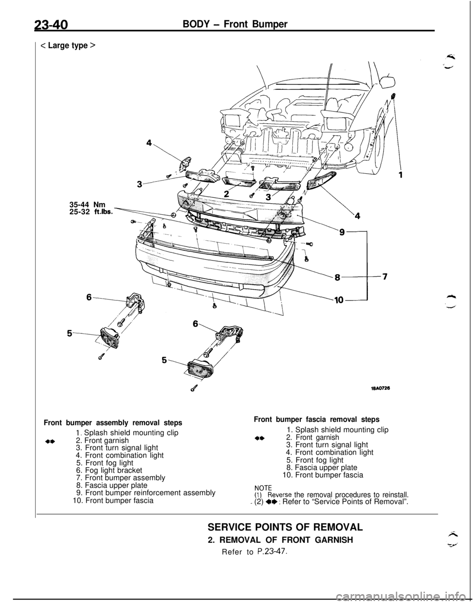
c Large type >
35-44 Nm
25-32
ft.lbs.
c4WA0726
Front bumper assembly removal steps
1, Splash shield mounting clip
4*2. Front garnish
3. Front turn signal light
4. Front combination light
5. Front fog light
6. Fog light bracket
7. Front bumper assembly
8. Fascia upper plate
9. Front bumper reinforcement assembly
10. Front bumper fascia
Front bumper fascia removal steps1. Splash shield mounting clip
4*2. Front garnish3. Front turn signal light
4. Front combination light
5. Front fog light
8. Fascia upper plate
10. Front bumper fasciaFr)?everse
the removal procedures to reinstall.- (2) +I) : Refer to “Service Points of Removal”.
SERVICE POINTS OF REMOVAL
2. REMOVAL OF FRONT GARNISH
Refer to P.23-47.
Page 1087 of 1216
BODY - Rear Bumper23-43
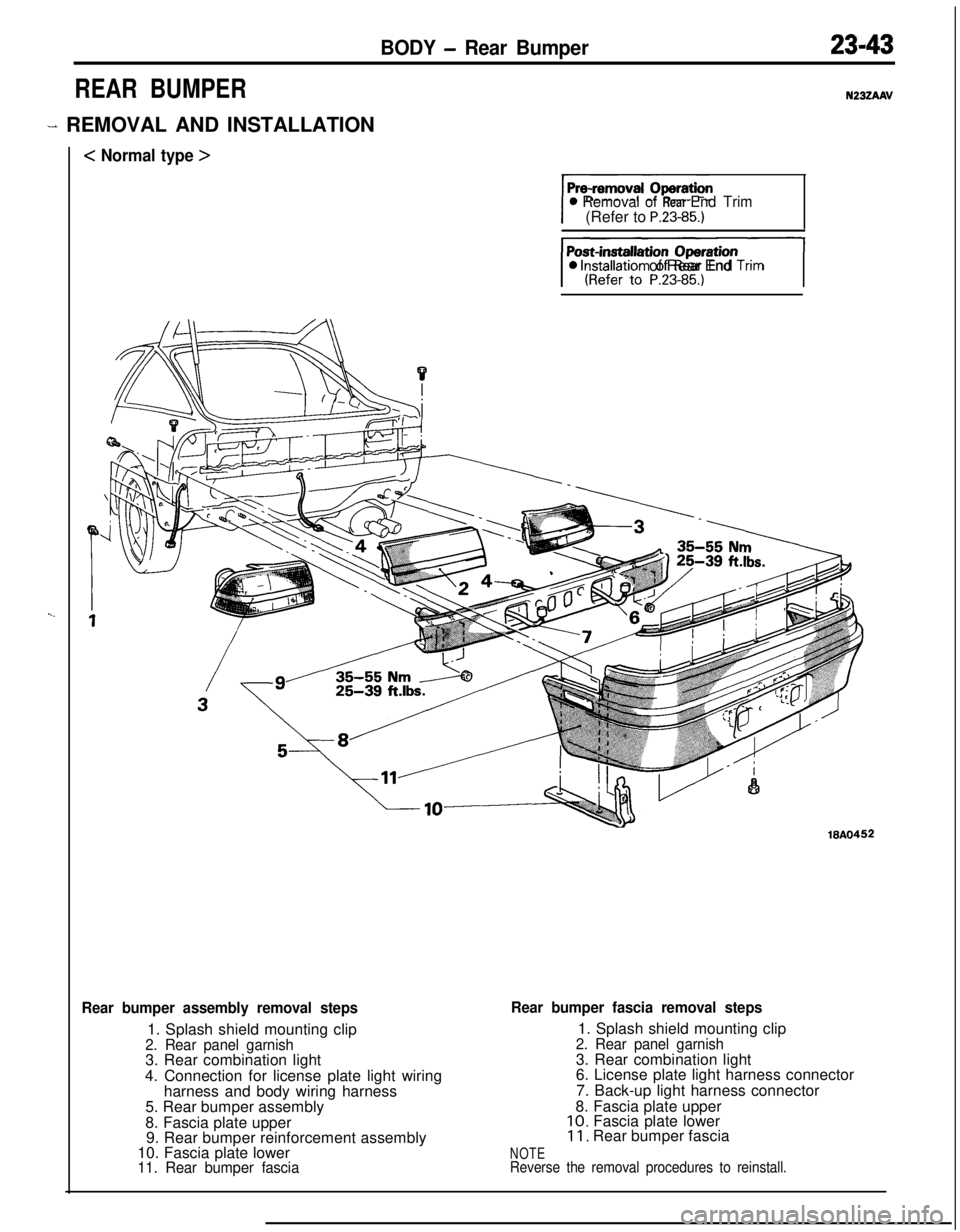
REAR BUMPER
- REMOVAL AND INSTALLATION
< Normal type >
N23ZAAV
0 Removal of Rear End Trim(Refer to P.23-85.)
JI0 lnstallatron of Rear End Tnm
18A0452
Rear bumper assembly removal steps1. Splash shield mounting clip
2. Rear panel garnish3. Rear combination light
4. Connection for license plate light wiring
harness and body wiring harness
5. Rear bumper assembly
8. Fascia plate upper
9. Rear bumper reinforcement assembly
10. Fascia plate lower
11. Rear bumper fascia
Rear bumper fascia removal steps1. Splash shield mounting clip
2. Rear panel garnish3. Rear combination light
6. License plate light harness connector
7. Back-up light harness connector
8. Fascia plate upper
10. Fascia plate lower11. Rear bumper fascia
NOTEReverse the removal procedures to reinstall.
Page 1088 of 1216
![MITSUBISHI ECLIPSE 1991 Service Manual < Large type >
]0 lnstallatron of Rear End Tnm
23-44BODY - Rear Bumper
18AO722
Rear bumper assembly removal steps1. Splash shield mounting clip
2. Rear panel garnish3. Rear combination light
4. Connec MITSUBISHI ECLIPSE 1991 Service Manual < Large type >
]0 lnstallatron of Rear End Tnm
23-44BODY - Rear Bumper
18AO722
Rear bumper assembly removal steps1. Splash shield mounting clip
2. Rear panel garnish3. Rear combination light
4. Connec](/img/19/57104/w960_57104-1087.png)
< Large type >
]0 lnstallatron of Rear End Tnm
23-44BODY - Rear Bumper
18AO722
Rear bumper assembly removal steps1. Splash shield mounting clip
2. Rear panel garnish3. Rear combination light
4. Connection for license plate light wiring
harness and body wiring harness
5. Rear bumper assembly8. Fascia plate upper
9. Rear bumper reinforcement assembly
10. Fascia plate lower11. Rear bumper fascia
Rear bumper fascia removal steps1. Splash shield mounting clip
2. Rear panel garnish3. Rear combination light
6. License plate light harness connector
7. Back-up light harness connector
8. Fascia plate upper
10. Fascia plate lower
11. Rear bumper fascia
NOTEReverse the removal procedures to reinstall.
Page 1089 of 1216

BODY - Rear Bummer23-45
DISASSEMBLY AND REASSEMBLY<
Normal type >
Disassembly steps1. License plate light
2. Back-up light
3. Rear side marker light
4. License plate light wiring harness
5. Bumper absorber
6. Rear bumper reinforcement
7. License plate bracket
8. Rear bumper fasciaNOTE
(1) Reverse the disassembly procedures to reassemble.(2) +* : Refer to “Service Points of Disassembly”.
SERVICE POINTS OF DISASSEMBLY5. REMOVAL OF BUMPER ABSORBER
Caution1. Do not attempt to repair a bumper absorber that has
been compressed in an accident; replace it with a new
one.2. Before discarding the bumper absorber, drill a 3 mm
(. 13 in.) diameter hole to discharge the gas containedin the unit.
3.
If the bumper absorber is to be discarded, do not burn
it.