light MITSUBISHI ECLIPSE 1991 Service Manual
[x] Cancel search | Manufacturer: MITSUBISHI, Model Year: 1991, Model line: ECLIPSE, Model: MITSUBISHI ECLIPSE 1991Pages: 1216, PDF Size: 67.42 MB
Page 1090 of 1216
23-46BODY - Rear Bumper
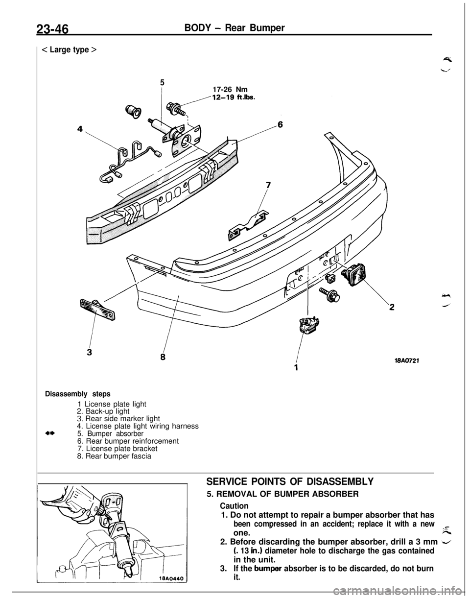
< Large type >
517-26 Nm
18A0721
Disassembly steps1 License plate light
2. Back-up light
3. Rear side marker light
4. License plate light wiring harness
4*5. Bumper absorber6. Rear bumper reinforcement
7. License plate bracket
8. Rear bumper fascia
SERVICE POINTS OF DISASSEMBLY5. REMOVAL OF BUMPER ABSORBER
Caution1. Do not attempt to repair a bumper absorber that has
been compressed in an accident; replace it with a new-one.
-F--2. Before discarding the bumper absorber, drill a 3 mm
-z
(. 13 in.1 diameter hole to discharge the gas containedin the unit.
3.
If the bumper absorber is to be discarded, do not burn
it.
Page 1093 of 1216
BODY - Moulding23-493.
REMOVAL OF QUARTER WINDOW MOULDING LOWER/
4. QUARTER WINDOW MOULDING UPPER/B. QUARTERWINDOW MOULDING FRONT
Refer to
P.23-61.6. REMOVAL OF
LIFTGATE MOULDING LOWERI7. LIFT-GATE MOULDING
UPPER/8. LIFTGATE MOULDING
SIDERefer to
P.23-62.
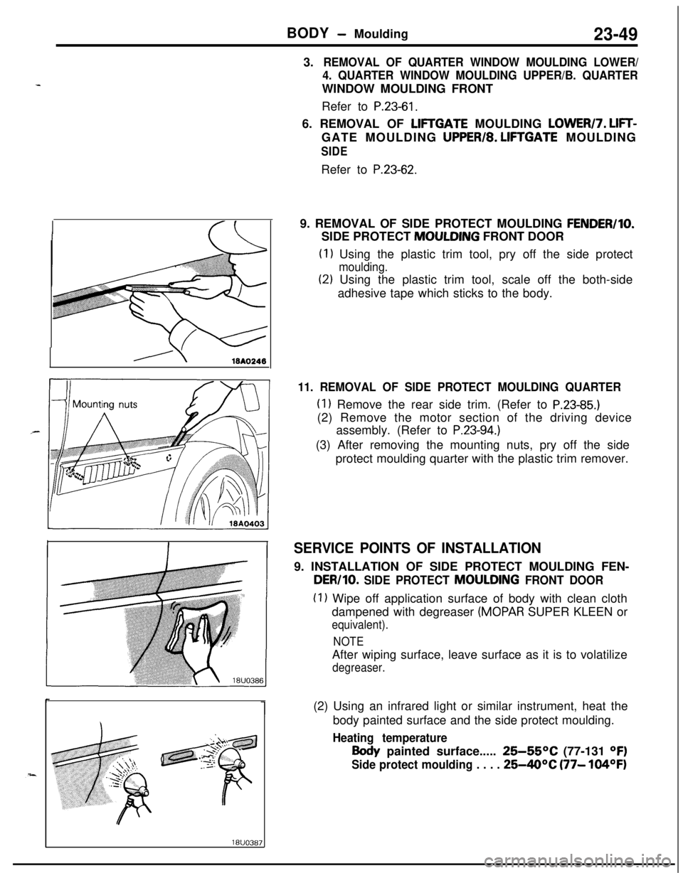
19. REMOVAL OF SIDE PROTECT MOULDING
FENDER/IO.SIDE PROTECT MOULDING FRONT DOOR
(1) Using the plastic trim tool, pry off the side protect
moulding.
(2) Using the plastic trim tool, scale off the both-side
adhesive tape which sticks to the body.
11. REMOVAL OF SIDE PROTECT MOULDING QUARTER
(1) Remove the rear side trim. (Refer to P.23-85.)(2) Remove the motor section of the driving device
assembly. (Refer to
P.23-94.)(3) After removing the mounting nuts, pry off the side
protect moulding quarter with the plastic trim remover.
SERVICE POINTS OF INSTALLATION9. INSTALLATION OF SIDE PROTECT MOULDING FEN-
DER/10. SIDE PROTECT MOULDING FRONT DOOR
(1) Wipe off application surface of body with clean cloth
dampened with degreaser
(MOPAR SUPER KLEEN or
equivalent).
NOTEAfter wiping surface, leave surface as it is to volatilize
degreaser.(2) Using an infrared light or similar instrument, heat the
body painted surface and the side protect moulding.
Heating temperature
Body painted surface..... 25-55OC (77-131 OF)
Side protect moulding . . . . 25-40°C (77- 104OF)
Page 1095 of 1216
BODY - Fender
FENDER
:- REMOVAL AND INSTALLATION
-.
Pre-removal Operation0 Removal of Front Garnish
(Refer to P.23-47.)l Removal of Front Turn Signal Light
and Front Combination Light
(Refer to GROUP 8-Front Combi-
nation Light)
l Removal of Headlight Lower Bezel
(Refer to GROUP
8-Headlights)l Removal of Side Air Dam
(Refer to
P.23-74.)LLu23KAAr
Post-installation Operation0 Installation of Side Air Dam
(Refer to P.23-74.)l Installation of Headlight Lower
Bezel
(Refer to GROUP
8-Headlight)0 Installation of Front Turn Signal
Light and Front Combination Light
(Refer to GROUP
8-Front Combi-
nation Light)
0 Installation of Front Garnish
(Refer to P.23-47.)J
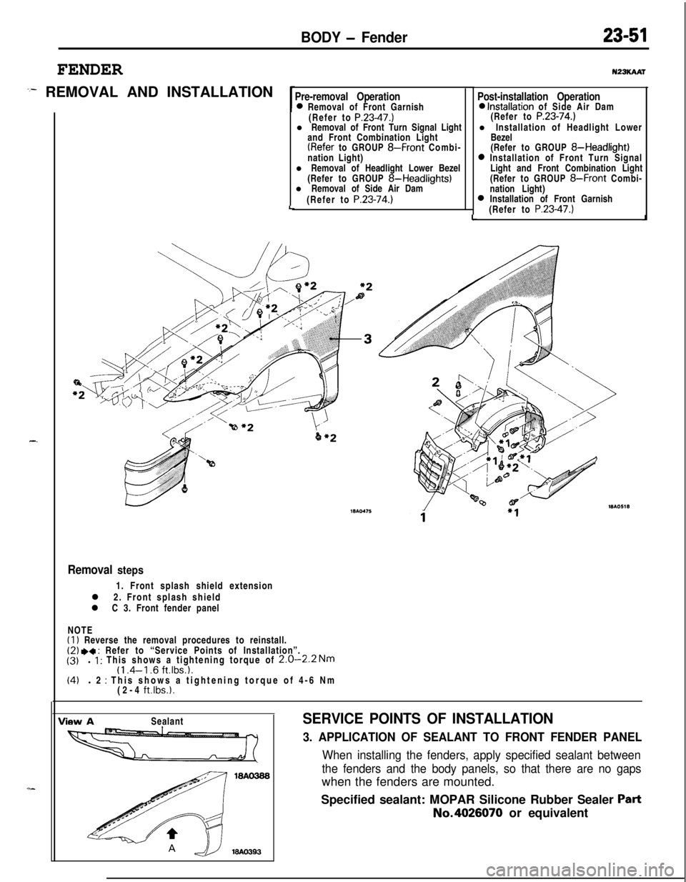
Removal steps1. Front splash shield extension
l 2. Front splash shield
l C 3. Front fender panel
NOTE
(1) Reverse the removal procedures to reinstall.(2) .a : Refer to “Service Points of Installation”.
(3)l 1 : This shows a tightening torque of 2.0-2.2 Nm(1 .4-l .6 ft.lbs.1.(4)l 2 : This shows a tightening torque of 4-6 Nm
(2-4 ft.lbs.1.
View ASealantSERVICE POINTS OF INSTALLATION
3. APPLICATION OF SEALANT TO FRONT FENDER PANEL
When installing the fenders, apply specified sealant between
the fenders and the body panels, so that there are no gapswhen the fenders are mounted.
Specified sealant: MOPAR Silicone Rubber Sealer
PartNo.4026070 or equivalent
Page 1097 of 1216
BODY - Loose Panel
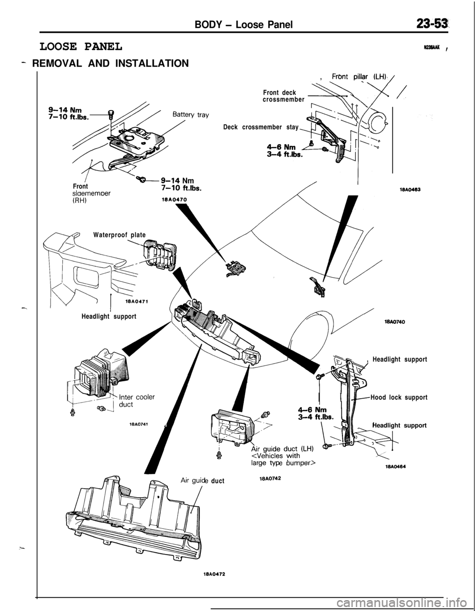
LOOSE PANEL
- REMOVAL AND INSTALLATION
, Frbnt
piI@ (LH),/
N22SAAK ,
-.
v trayFront deck
crossmember
+ADeck crossmember stay
/Front
I
‘-9-14 Nm7-10 ftlbs.slaememoer
mWaterproof plate\K?%--
(RH)
WA0471Headlight supportWA.0741
,
/
WA0463, Headlight support
/-c---x/
I IHood lock support
_Headlight supporte duct
MA0742
WA0472
e Dumper,18AO484
Page 1118 of 1216
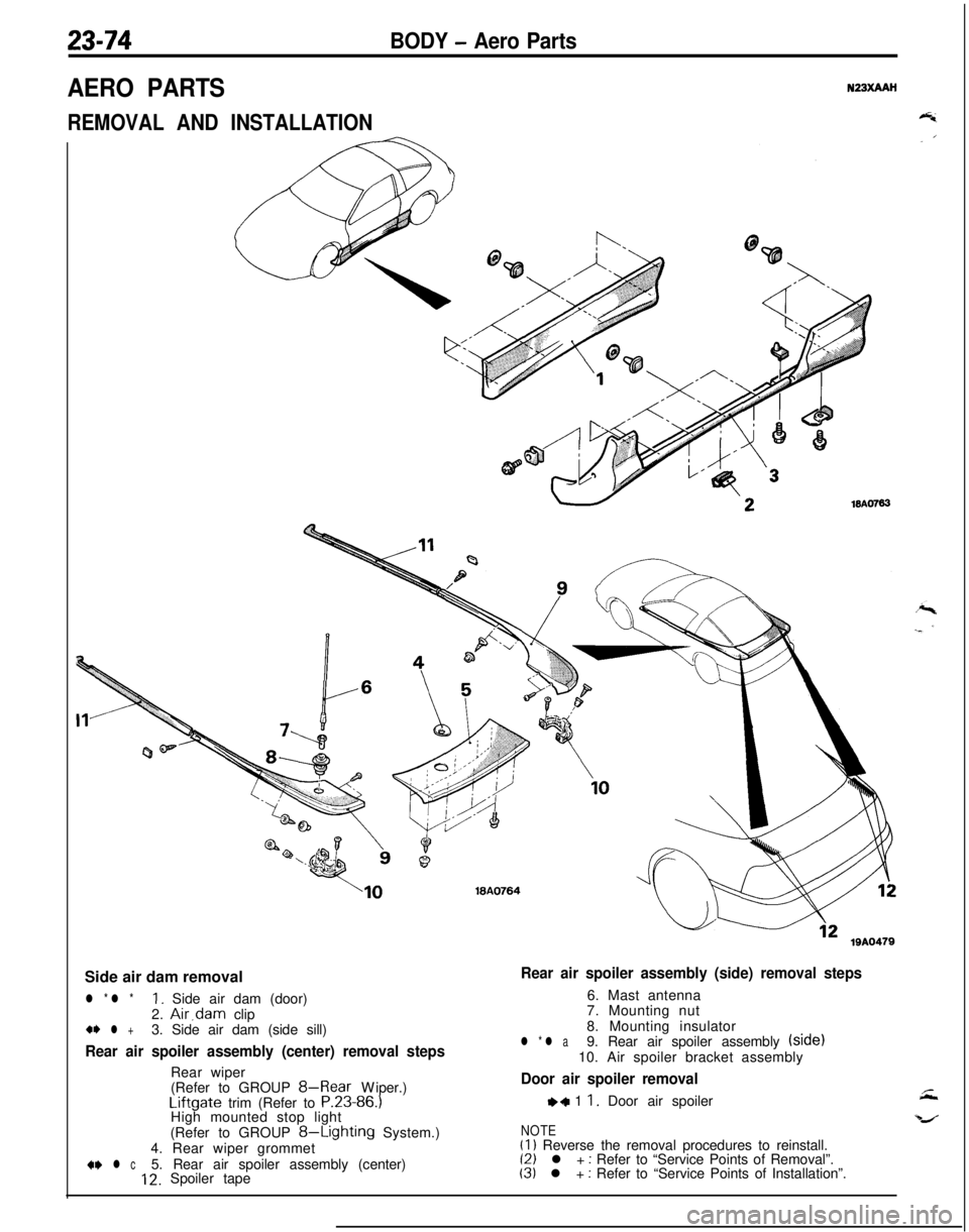
23-74BODY - Aero Parts
AERO PARTSN23XAAH
REMOVAL AND INSTALLATION
WA076318A0764
lQA0479Side air dam removal
l * l *1. Side air dam (door)
2. Air,dam clip+* l +3. Side air dam (side sill)
Rear air spoiler assembly (center) removal stepsRear wiper
(Refer to GROUP
8-Rear Wiper.)Liftgate trim (Refer to P.23-86.)
High mounted stop light
(Refer to GROUP
8-Lighting System.)
4. Rear wiper grommet
+w l c5. Rear air spoiler assembly (center)12. Spoiler tape
Rear air spoiler assembly (side) removal steps6. Mast antenna
7. Mounting nut
8. Mounting insulator
l * l a9. Rear air spoiler assembly (side)
10. Air spoiler bracket assembly
Door air spoiler removal
,+ 1 1. Door air spoiler
NOTE(1) Reverse the removal procedures to reinstall.(2) l + : Refer to “Service Points of Removal”.(3) l + : Refer to “Service Points of Installation”.
Page 1120 of 1216
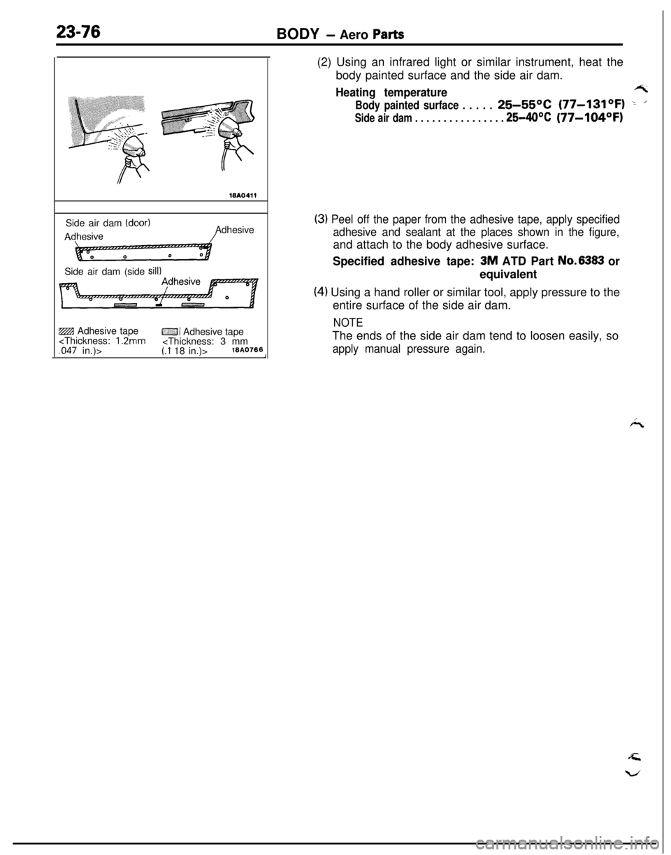
23-76BODY - Aero Parts
WA0411Side air dam
(door)AAdhesive
Side air dam (side
sill)ZBI Adhesive tape
CZJI Adhesive tape
body painted surface and the side air dam.
Heating temperaturert
Body painted surface . . . . .25-55OC (77-131OF) -. ’
Side air dam . . . . . . . . . . . . . . . . 25-40°C(77-104OFI
(3) Peel off the paper from the adhesive tape, apply specified
adhesive and sealant at the places shown in the figure,and attach to the body adhesive surface.
Specified adhesive tape:
3M ATD Part No.6383 or
equivalent
(4) Using a hand roller or similar tool, apply pressure to the
entire surface of the side air dam.
NOTEThe ends of the side air dam tend to loosen easily, so
apply manual pressure again.
Page 1125 of 1216

BODY - Instrument Panel23-81
SECT. A-A
Flat-tip
( - ) screwdriver19A0274
1910267
SERVICE POINTS OF REMOVAL
10. REMOVAL OF CENTER AIR OUTLET ASSEMBLY
Removing the paw1 of the center air outlet assembly with aflat-tip
( - 1 screwdriver,remove the center air outlet
assembly with the plastic trim tool.
16. REMOVAL OF SPEEDOMETER CABLE ADAPTER
(1) Disconnect the speedometer cable at the transaxle endof the cable.
(2) Pull the speedometer cable slightly toward the vehicle
interior, release the lock by turning the adapter to the leftor right, and then remove the adapter.
Page 1126 of 1216
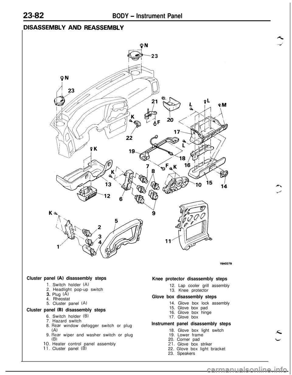
23-82BODY - Instrument Panel
9N23
Cluster panel (A) disassembly steps
1. Switch holder (A)2. Headlight pop-up switch
3. Plug
(A)4. Rheostat
5. Cluster panel
(A)
Cluster panel (B) disassembly steps6. Switch holder
(5)7. Hazard switch
8.
p;Fr window defogger switch or plug
9.
$far wiper and washer switch or plug10. Heater control panel assembly
II. Cluster panel (B)
Knee protector disassembly steps12. Lap cooler grill assembly
13. Knee protector
Glove box disassembly steps14. Glove box lock assembly
15. Glove box pad
16. Glove box hinge
17. Glove box
Instrument panel disassembly steps18. Glove box light switch
19. Lower frame
20. Corner pad21. Glove box striker
22. Glove box light bracket
23. Speakers
Page 1128 of 1216
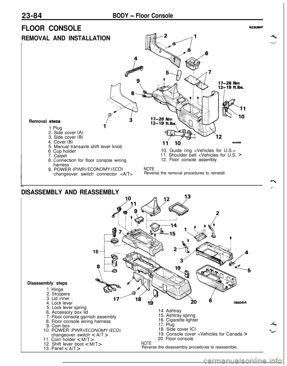
23-84BODY - Floor Console
FLOOR CONSOLEN23lJBAP
REMOVAL AND INSTALLATIONGk2 /---I
Removal stew1 Plug
2. Side cover
(A)3. Side cover (B)4. Cover
(6)5. Manual transaxle shift lever knob
6. Cup holder7. Carpet8. fCor;e~tion for floor console wiring
9. POWER
(PWR)/ECONOMY (EC01changeover switch connector
11'ld19102e1)10. Guide ring
11. Shoulder belt
NOTEReverse the removal procedures to reinstall.
DISASSEMBLY AND REASSEMBLY16
19AO414
Disassembly steps
1. Hinge
2. Stoooers3. Lid ‘inneF4. Lock lever
5. Lock lever spring
6. Accessory box lid
7. Floor console garnish assembly
8. Floor console wiring harness
9. Coin box
10. POWER (PWR)/ECONOMY (ECO)changeover switch < AIT >11. Coin holder < M/T>12. Shift lever boot
15. Ashtray spring
16. Cigarette lighter
17. Plug18. Side cover (C)19. Console cover
NOTEReverse the disassembly procedures to reassemble.
Page 1130 of 1216
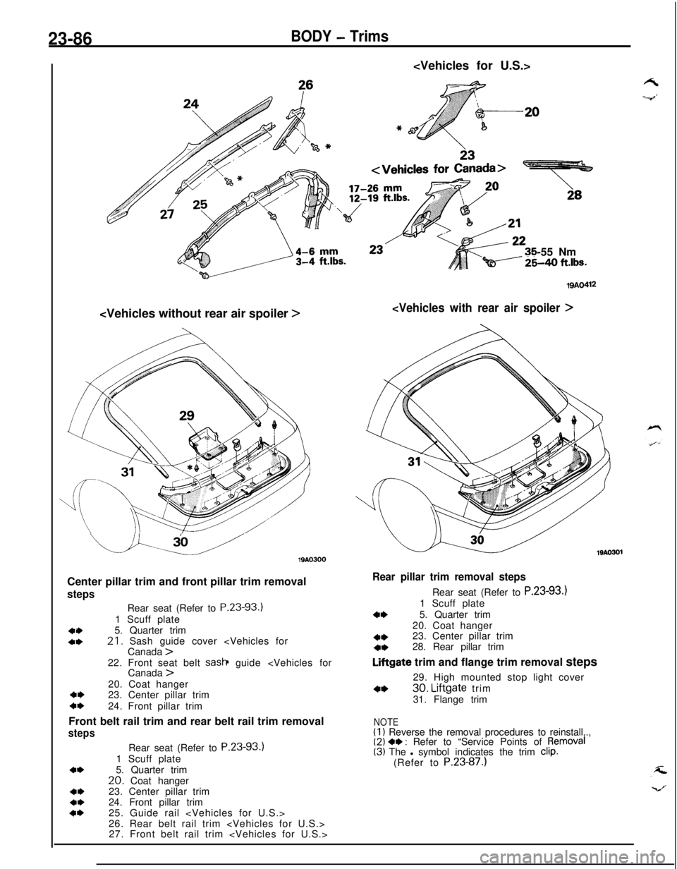
23-86BODY - Trims
-55 Nm
Qi----- %40 ft.lbs.
u.u19AO300
Center pillar trim and front pillar trim removal
steps
404,Rear seat (Refer to P.23-93.)
1 Scuff plate
5. Quarter trim21. Sash guide cover
4,23. Center pillar trimc*24. Front pillar trim
Front belt rail trim and rear belt rail trim removal
steps
4*
4,4*4*Rear seat (Refer to P.23-93.)
1 Scuff plate
5. Quarter trim
20. Coat hanger
23. Center pillar trim
24. Front pillar trim
25. Guide rail
26. Rear belt rail trim
27. Front belt rail trim
19AO412
19AO301
Rear pillar trim removal stepsRear seat (Refer to P.23-93.)
1 Scuff plate
4*5. Quarter trim
20. Coat hanger
4*23. Center pillar trim4*28. Rear pillar trim
Liftgate trim and flange trim removal steps
29. High mounted stop light cover
4*30. Liftgate trim
31. Flange trim
NOTE(1) Reverse the removal procedures to reinstall,.,(2) 4, : Refer to “Service Points of pemoval(3) The l symbol indicates the trim clip.(Refer to P.23-87.)