MITSUBISHI ECLIPSE 1991 Service Manual
Manufacturer: MITSUBISHI, Model Year: 1991, Model line: ECLIPSE, Model: MITSUBISHI ECLIPSE 1991Pages: 1216, PDF Size: 67.42 MB
Page 1201 of 1216
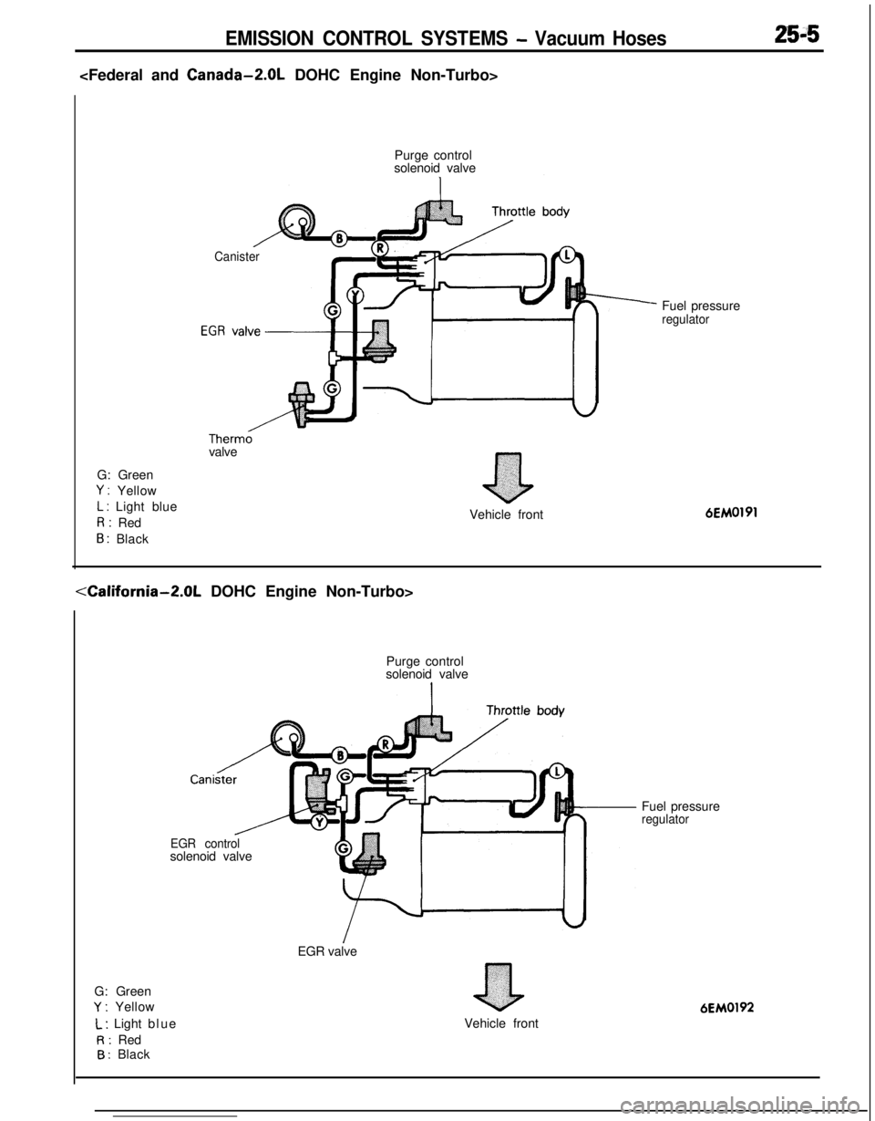
EMISSION CONTROL SYSTEMS - Vacuum Hoses2515
Purge control
solenoid valve
Canister
Therm0valve
G: Green
Y : Yellow
L : Light blueR: Red
B : Black
nVehicle frontFuel pressure
regulator6EM0191
G: Green
Y : YellowPurge control
solenoid valve
Cani
EGR controlsolenoid valve
EGR valve
L : Light blue
R: Red
B : BlackVehicle frontFuel pressure
regulator
6EM0192
Page 1202 of 1216

25-6EMISSION CONTROL SYSTEMS - Vacuum Hoses
G: Green
Y : Yellow
L : Light blueR: Red
B : Black
W: White
Purge control valvg
Purge controlFuel pressure control,solenoid valve/solenoid valve
Therm0 valve’
el pressure regulator
Turbocharger
vvasre gate actuator Waste gate control
solenoid valveVehicle front
6EM0222
G: Green
Y : Yellow
L : Lrght blueR: Red
B : Black
W: White
1sPurge control valve
&+
Air cleanerFuel pressure control
solenoid valve.
Purge control
solenoid valve\Fuel pressure regulator
Waste gate control
solenord valve
Waste gate actuatorv.,~~‘~y:‘;7Vehicle front
6EM0223
Page 1203 of 1216
EMISSION CONTROL SYSTEMS - vacuumHoses/Crankcase Emission Control System25-7
INSPECTION(1) Referring to the VACUUM HOSES ROUTING,
confirm2the vacuum hoses are properly connected.
(2) Check the hoses for irregularities (disconnection, loose-
ness, etc.) and confirm that there is no breakage or
damage.INSTALLATION
’N2SJDAD(1) When connecting a hose, firmly press it onto the nipple.
(2) Referring to the VACUUM HOSES ROUTING, connect the
hoses correctly.
CRANKCASE EMISSION CONTROL SYSTEM
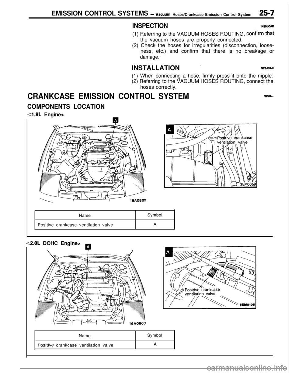
COMPONENTS LOCATION<1.8L Engine>
ventilation valve
NameSymbol
Positive crankcase ventilation valveA<2.0L DOHC Engine>
A
\T/Name
Posltive crankcase ventilation valveSymbol
A
Page 1204 of 1216
25-8EMISSION CONTROL SYSTEMS - Crankcase Emission Control System
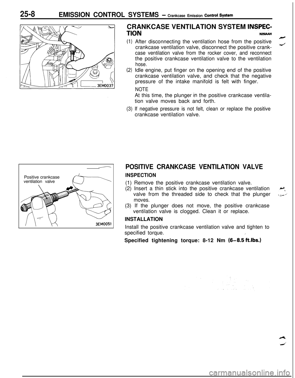
-Positive crankcase
ventilation valve3EM0051CRANKCASE VENTILATION SYSTEM
INSPEC-
TIONNZSIAAHAfter disconnecting the ventilation hose from the positive
crankcase ventilation valve, disconnect the positive crank-
case ventilation valve from the rocker cover, and reconnectthe positive crankcase ventilation valve to the ventilation
hose.
Idle engine, put finger on the opening end of the positive
crankcase ventilation valve, and check that the negative
pressure of the intake manifold is felt with finger.
NOTEAt this time, the plunger
Ian the positive crankcase ventila-
tion valve moves back and forth.
(3) If negative pressure is not felt, clean or replace the positivecrankcase ventilation valve.
POSITIVE CRANKCASE VENTILATION VALVE
INSPECTION(1) Remove the positive crankcase ventilation valve.
(2) Insert a thin stick into the positive crankcase ventilation
valve from the threaded side to check that the plunger
moves.(3) If the plunger does not move, the positive crankcase
ventilation valve is clogged. Clean it or replace.
INSTALLATION
Install the positive crankcase ventilation valve and tighten to
specified torque.
iSpecified tightening torque: 8-12 Nm
(8-8.5 ft.lbs.)
Page 1205 of 1216
EMISSION CONTROL SYSTEMS- Evaporative Emission Control System
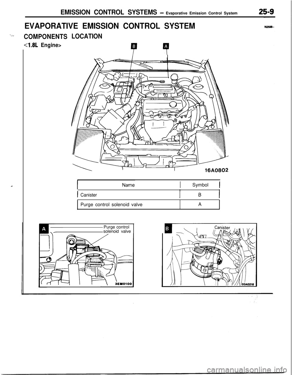
EVAPORATIVE EMISSION CONTROL SYSTEM
‘2,COMPONENTS
4.81,Engine>
r
LOCATION
P 4
xl-#i
ISymbol 1
ICanisterPurge control solenoid valveA
Purge control
solenoid valve
Page 1206 of 1216
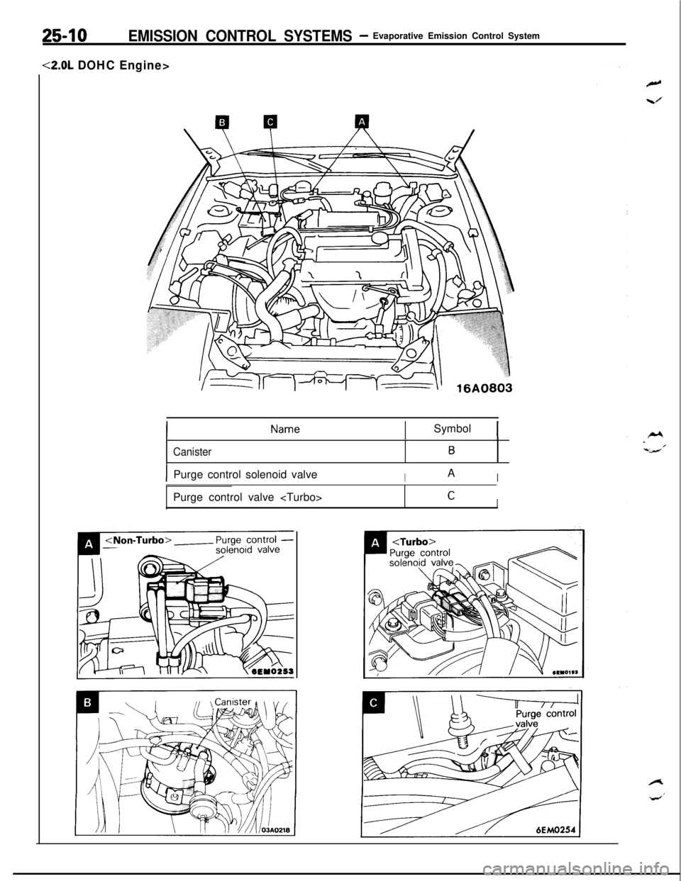
25-10EMISSION CONTROL SYSTEMS- Evaporative Emission Control System
<2.0L DOHC Engine>
ISymbol 1
Canister
1
B
IPurge control solenoid valveIAIPurge control valve
CI
Page 1207 of 1216

EMISSION CONTROL SYSTEMS- Evaporative Emission Control SYStem25-m
PURGE CONTROL SYSTEM INSPECTION
sensor
P+
Engine control unit
IlEM0086(1) Disconnect the vacuum hose (red stripes) from the throttle
body and connect it to a hand vacuum pump.
(2) Plug the nipple from which the vacuum hose is discon-
nected.(3) Under the engine conditions shown below, check by
applying vacuum from a hand vacuum pump.
When engine is cold-engine coolant temperature:
60% (140°F) or less
Engine operating Applying vacuum
>When engine is hot-engine coolant temperature:
70°C (158°F) or higher
Engine operating
condition
Idling3,000 rpm within
three minutes afterstarting engine
3,000 rpm after
three minutes
have elapsedafter starting
engineApplying vacuum
375
mmHg(14.8 in.Hg.1
Try wpMwvacuum375
mmHg(14.8 in.Hg.1
ResultVacuum is maintained
Vacuum leaks
Vacuum will be main-
tained momentarily,
after which it will
leaks.
NOTEThe vacuum will leak
continuously if the
altitude is 2,200
m(7,200 ft.) or higher,or the intake air
temperature is
50°C(122°F) or higher.
Page 1208 of 1216
25-12EMISSION CONTROL SYSTEMS -Evaporative Emission Control System
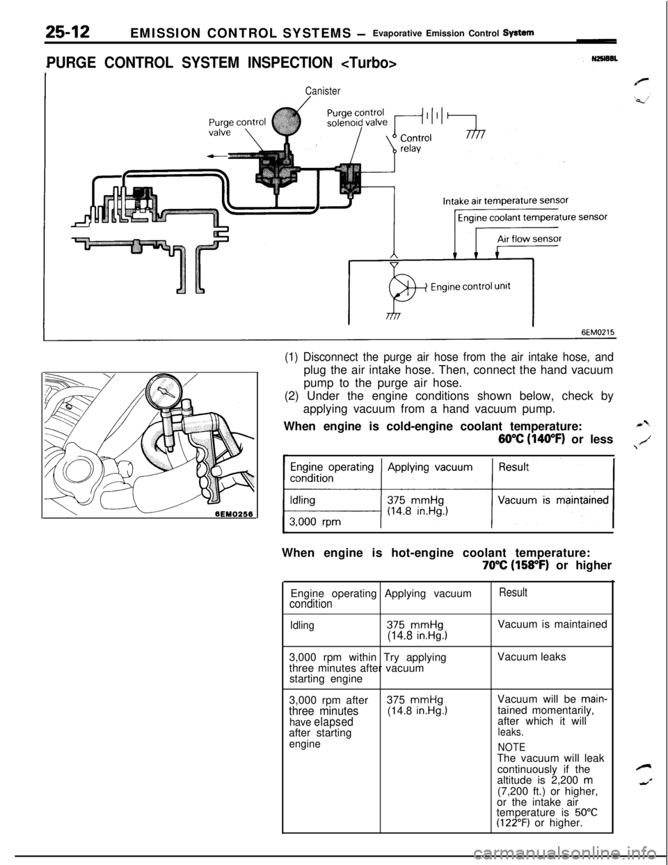
PURGE CONTROL SYSTEM INSPECTION
Canister
6EM0215
(1) Disconnect the purge air hose from the air intake hose, andplug the air intake hose. Then, connect the hand vacuum
pump to the purge air hose.
(2) Under the engine conditions shown below, check by
applying vacuum from a hand vacuum pump.
When engine is cold-engine coolant temperature:
60°C (140°F) or less
Engine operating Applying vacuum
11When engine is hot-engine coolant temperature:
70°C (158°F) or higher
Engine operating Applying vacuum
condition
Result
Idling375 mmHg(14.8 in.Hg.)Vacuum is maintained
3,000 rpm within Try applying
three minutes after vacuum
starting engineVacuum leaks
3,000 rpm after375
mmHgVacuum will be main-
three minutes(14.8 in.Hg.1tained momentarily,
have elapsedafter which it will
after startingleaks.
engineNOTEThe vacuum will leak
continuously if the
altitude is 2,200
m(7,200 ft.) or higher,
or the intake air
temperature is
50°C(122°F) or higher.
Page 1209 of 1216
EMISSION CONTROL SYSTEMS- Evaporative Emission Control System25-WECl51C
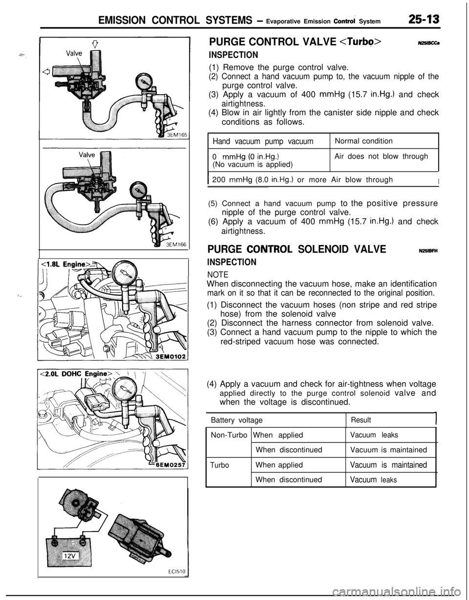
PURGE CONTROL VALVE
INSPECTION
NZSIBCCJ(1) Remove the purge control valve.
(2) Connect a hand vacuum pump to, the vacuum nipple of thepurge control valve.
(3) Apply a vacuum of 400 mmHg (15.7
in.Hg.) and check
airtightness.(4) Blow in air lightly from the canister side nipple and check
conditions as follows.
Hand vacuum pump vacuum0
mmHg (0 in.Hg.1(No vacuum is applied)Normal condition
Air does not blow through
I200 mmHg (8.0 in.Hg.) or more Air blow throughI(5) Connect a hand vacuum pump to the positive pressure
nipple of the purge control valve.
(6) Apply a vacuum of 400 mmHg (15.7
in.Hg.) and check
airtightness.
PURGE CQNTROL SOLENOID VALVE
INSPECTION
NOTE
NZBIBFHWhen disconnecting the vacuum hose, make an identification
mark on it so that it can be reconnected to the original position.(1) Disconnect the vacuum hoses (non stripe and red stripe
hose) from the solenoid valve
(2) Disconnect the harness connector from solenoid valve.
(3) Connect a hand vacuum pump to the nipple to which the
red-striped vacuum hose was connected.
(4) Apply a vacuum and check for air-tightness when voltage
applied directly to the purge control solenoid valve and
when the voltage is discontinued.
Battery voltage
Result1Non-Turbo When applied
When discontinued
TurboWhen applied
When discontinued
Vacuum leaksVacuum is maintained
Vacuum is maintained
Vacuum
leaks
Page 1210 of 1216
![MITSUBISHI ECLIPSE 1991 Service Manual 25-14EMISSION CONTROL SYSTEMS- Evaporative Emission Control System
(5) Measure the resistance between the terminals of the
solenoid valve.
Standard value: 36-44
Q [at 20°C (68OF)]_
6EM137
AIR FLOW S MITSUBISHI ECLIPSE 1991 Service Manual 25-14EMISSION CONTROL SYSTEMS- Evaporative Emission Control System
(5) Measure the resistance between the terminals of the
solenoid valve.
Standard value: 36-44
Q [at 20°C (68OF)]_
6EM137
AIR FLOW S](/img/19/57104/w960_57104-1209.png)
25-14EMISSION CONTROL SYSTEMS- Evaporative Emission Control System
(5) Measure the resistance between the terminals of the
solenoid valve.
Standard value: 36-44
Q [at 20°C (68OF)]_
6EM137
AIR FLOW SENSOR, ENGINE COOLANT TEMPER-
ATURE SENSOR AND INTAKE AIR TEMPERA-
TURE SENSORTo inspect these parts, refer to GROUP
14-MPI System
Components.‘.
AIR CONDITIONER SWITCHTo inspect the air conditioner switch, refer to GROUP
24’--AirConditioner Switch.
OVERFILL LIMITER (TWO-WAY VALVE)N2BlBE&To inspect the overfill limiter (two-way valve), refer to GROUP
14-Fuel Tank.
CANISTERNzslBmTo inspect the canister, refer to GROUP
14-Fuel Line and
Vapor Line.
FUEL FILLER CAP INSPECTIONNZSIBJACheck the gasket of the fuel filler cap, and, the filler cap itself,
for damage or deformation; replace the cap if necessary.