MITSUBISHI ECLIPSE 1991 Service Manual
Manufacturer: MITSUBISHI, Model Year: 1991, Model line: ECLIPSE, Model: MITSUBISHI ECLIPSE 1991Pages: 1216, PDF Size: 67.42 MB
Page 141 of 1216
BRAKES
SERVICE AND PARKING
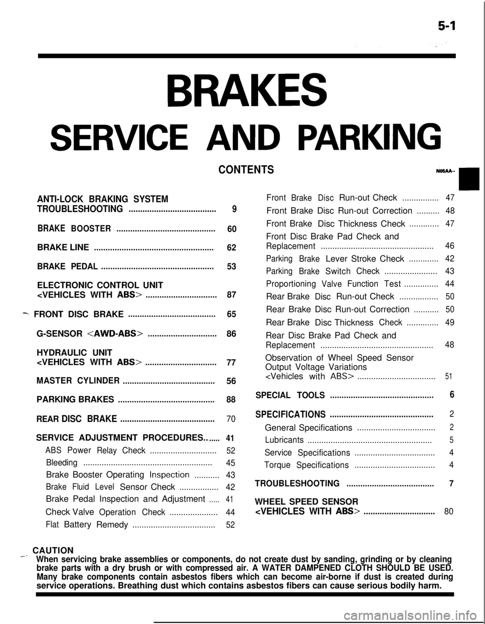
CONTENTS
ANTI-LOCK BRAKING SYSTEM
TROUBLESHOOTING
......................................
9
BRAKEBOOSTER...........................................
60BRAKE LINE
....................................................
62
BRAKE PEDAL.................................................
53ELECTRONIC CONTROL UNIT
- FRONT DISC BRAKE......................................
65G-SENSOR
HYDRAULIC UNIT
77
MASTERCYLINDER
........................................56
PARKING BRAKES
..........................................88
REAR
DISC BRAKE.........................................70SERVICE ADJUSTMENT PROCEDURES..
.....41
ABSPowerRelayCheck.............................52
Bleeding........................................................
45Brake Booster Operating
Inspection...........43
BrakeFluidLevelSensor Check.................
42Brake Pedal Inspection and Adjustment
.....41Check Valve
OperationCheck.....................
44
FlatBattery
Remedy....................................52
FrontBrakeDiscRun-out Check................47Front Brake Disc Run-out Correction
..........48Front Brake
Disc Thickness Check
.............47Front Disc Brake Pad Check and
Replacement.................................................46
Parking
BrakeLever Stroke Check.............42
Parking
BrakeSwitchCheck.......................43
Proportioning
ValveFunctionTest...............44Rear Brake
DiscRun-out Check.................50Rear Brake Disc Run-out Correction
...........50Rear Brake
Disc Thickness
Check..............49Rear Disc Brake Pad Check and
Replacement.................................................48Observation of Wheel Speed Sensor
Output Voltage Variations
ABS>..................................51
SPECIAL TOOLS.............................................6
SPECIFICATIONS.............................................
2General Specifications
..................................2
Lubricants
......................................................5
Service
Specifications...................................4
Torque
Specifications...................................4
TROUBLESHOOTING......................................7WHEEL SPEED SENSOR
_ CAUTION
When servicing brake assemblies or components, do not create dust by sanding, grinding or by cleaning
brake parts with a dry brush or with compressed air. A WATER DAMPENED CLOTH SHOULD BE USED.
Many brake components contain asbestos fibers which can become air-borne if dust is created duringservice operations. Breathing dust which contains asbestos fibers can cause serious bodily harm.
Page 142 of 1216
5-2BRAKES - SDecifications
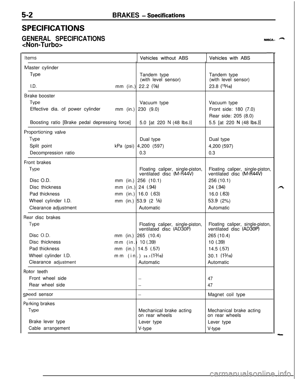
SPECIFICATIONS
GENERAL SPECIFICATIONS
NO!iCA-- -
ItemsItems
NNVehicles without ABS Vehicles without ABSVehicles with ABS Vehicles with ABS
BIBI
PlPl
Fr Frlaster cylinder
TypeTandem typeTandem type
(with level sensor)(with level sensor)
I.D.mm (in.) 22.2 (7/8)23.8 (‘%6)rake booster
TypeVacuum typeVacuum type
Effective dia. of power cylinder
mm (in.) 230 (9.0)Front side: 180 (7.0)
Rear side: 205 (8.0)
Boosting ratio [Brake pedal depressing force]
5.0 [at 220
N (48 Ibs.)]5.5 [at 220 N (48 Ibs.)]
.oportioning valve
TypeDual typeDual type
Split point
kPa (psi) 4,200 (597)
4,200 (597)
Decompression ratio
0.3
0.3ont brakes
TypeFloating caliper, single-piston,ventilated disc (M-R44V)Floating caliper, single-piston,ventilated disc (M-R44V)Disc O.D.
mm (in.) 256 (10.1)256 (10.1)
Disc thickness
mm (in.) 24
(.94)24 (.94)Pad thicknessmm (in.) 16.0 (63)
16.0
(.63)Wheel cylinder I.D.
mm (in.) 53.9 (2
l/8)53.9 (2%)
Clearance adjustmentAutomaticAutomatic
3ar disc brakes
TypeFloating caliper, single-piston,Floating caliper, single-piston,ventilated disc (AD30P)ventilated disc (AD30P)Disc
O.D.mm (in.) 265 (10.4)265 (10.4)
Disc thickness
mm (in.)
10 (39)10 i.39)Pad thickness
mm (in.) 14.5 (57)
14.5 (57)
Wheel cylinder I.D.
mm (in.) 30.1
(1 3/16)30.1 (1 346)Clearance adjustment
AutomaticAutomatic
)tor teeth
Front wheel side
-47Rear wheel side
-47
leed sensor-Magnet coil type
rking brakes
TypeMechanical brake actingMechanical brake acting
on rear wheelson rear wheels
Brake lever type
Lever type
Lever type
Cable arrangement
V-type
V-type
Rc Rc
SP SP
Pa Pa
Page 143 of 1216
BRAKES - Specifications5-3
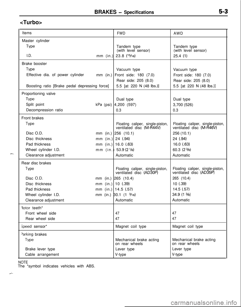
ItemsFWDAWDMaster cylinder
TypeTandem type
(with level sensor)Tandem type
(with level sensor)
I.D.mm (in.) 23.8 (‘%a)25.4 (1)Brake booster
TypeVacuum type
Vacuum type
Effective dia. of power cylinder
mm (in.) Front side: 180 (7.0)
Front side: 180 (7.0)
Rear side: 205 (8.0)
Rear side: 205 (8.0)
Boosting ratio [Brake pedal depressing force]
5.5 [at 220
N (48 Ibs.)]5.5 [at 220 N (48 Ibs.)]Proportioning valve
TypeDual typeDual type
Split point
kPa (psi) 4,200 (597)
3,700 (526)
Decompression ratio
0.30.3Front brakes
TypeFloating caliper, single-piston,Floating caliper, single-piston,ventilated disc (M-R44V)ventilated disc (M-R46V)Disc O.D.
mm (in.) 256 (10.1)256 (10.1)
Disc thickness
mm (in.) 24
(.94)24 (.94)Pad thickness
mm (in.) 16.0
(.63)16.0 (.63)Wheel cylinder I.D.
mm (in.)
53.9 (2 ‘16)60.3 (23%3)Clearance adjustment
AutomaticAutomatic
Rear disc brakes
TypeFloating caliper, single-piston,Floating caliper, single-piston,ventilated disc (AD30P)ventilated disc (AD35P)Disc
O.D.mm (in.) 265 (10.4)265 (10.4)Disc thicknessmm (in.) 10
(.39)10 f.39)Pad thicknessmm (in.) 14.5
(.57)14.5 (.57)Wheel cylinder I.D.mm (in.) 30.1 (1
3/16)34.9 (1 3h)Clearance adjustmentAutomaticAutomatic
qotor teeth*
Front wheel side
4747Rear wheel side
4747
speed sensor*Magnet coil typeMagnet coil type‘arking brakes
TypeMechanical brake actingMechanical brake acting
on rear wheelson rear wheels
Brake lever typeLever typeLever type
Cable arrangementV-typeV-type
NOTEThe *symbol indicates vehicles with ABS.
Page 144 of 1216
5-4BRAKES - Specifications
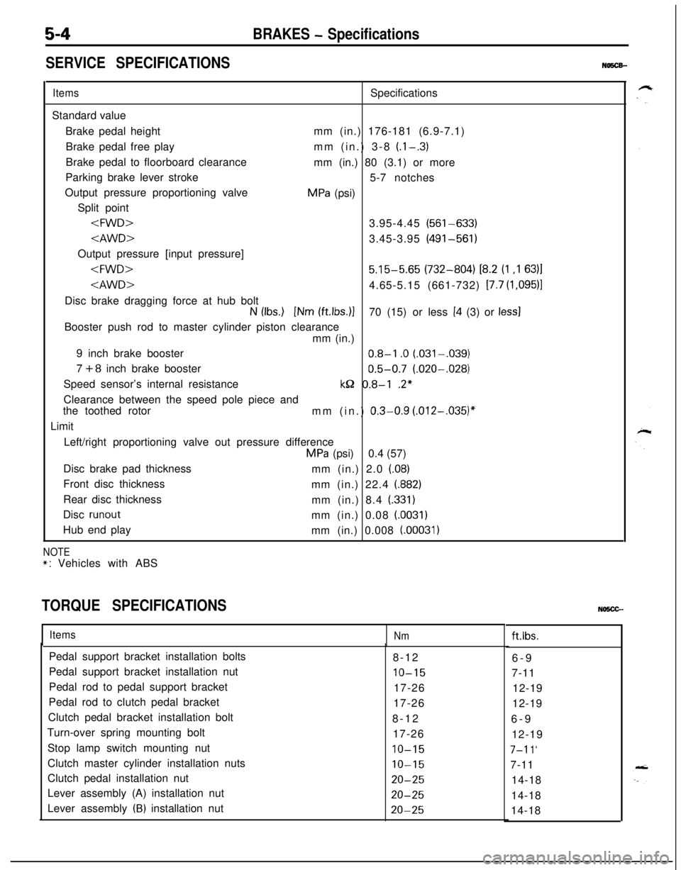
SERVICE SPECIFICATIONS
NO5CB-
ItemsSpecifications
Standard value
Brake pedal heightmm (in.) 176-181 (6.9-7.1)
Brake pedal free playmm (in.) 3-8
(l-.3)Brake pedal to floorboard clearance
mm (in.) 80 (3.1) or more
Parking brake lever stroke
5-7 notches
Output pressure proportioning valve
MPa (psi)
Split point
Output pressure [input pressure]
N (Ibs.) [Nm (ftlbs.)]70 (15) or less [4 (3) or less1Booster push rod to master cylinder piston clearance
mm (in.)
9 inch brake booster
0.8-l .O (.031-,039)
7
+8 inch brake booster0.5-0.7 (.020-.028)
Speed sensor’s internal resistance
kQ 0.8-l .2*
Clearance between the speed pole piece and
the toothed rotor
mm (in.)
0.3-0.9 (.012-,035)”Limit
Left/right proportioning valve out pressure difference
MPa (psi)0.4 (57)
Disc brake pad thickness
mm (in.) 2.0 (08)
Front disc thickness
mm (in.) 22.4 (882)
Rear disc thickness
mm (in.) 8.4
(.331)Disc
runoutmm (in.) 0.08 (.0031)Hub end play
mm (in.) 0.008
(.00031)
NOTE
*: Vehicles with ABS
TORQUE SPECIFICATIONS
ItemsNmft.lbs.
Pedal support bracket installation bolts
8-12
6-9
Pedal support bracket installation nut
IO-157-11
Pedal rod to pedal support bracket
17-26
12-19
Pedal rod to clutch pedal bracket
17-26
12-19
Clutch pedal bracket installation bolt
8-12
6-9
Turn-over spring mounting bolt
17-26
12-19
Stop lamp switch mounting nut
IO-157-l 1‘Clutch master cylinder installation nuts
10-157-11
Clutch pedal installation nut
20-2514-18
Lever assembly (A) installation nut
20-2514-18
Lever assembly
(B) installation nut20-2514-18
Page 145 of 1216
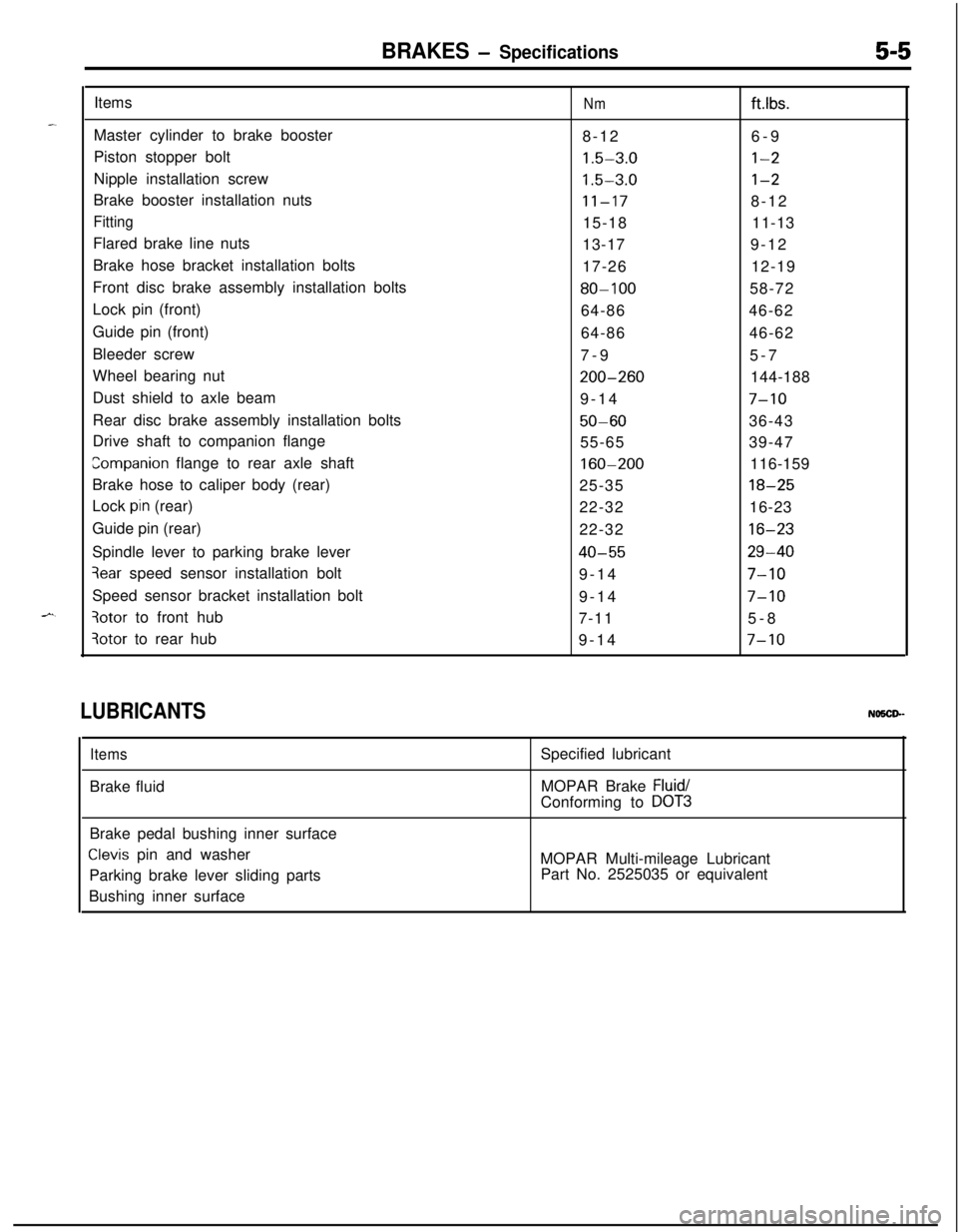
BRAKES - Specifications5-5Items
Nmftlbs.Master cylinder to brake booster
8-126-9
Piston stopper bolt
1.5-3.0l-2Nipple installation screw
1.5-3.0l-2Brake booster installation nuts
11-178-12
Fitting15-1811-13
Flared brake line nuts
13-179-12
Brake hose bracket installation bolts
17-2612-19
Front disc brake assembly installation bolts
80-10058-72
Lock pin (front)
64-8646-62
Guide pin (front)
64-8646-62
Bleeder screw
7-95-7
Wheel bearing nut
200-260144-188
Dust shield to axle beam
9-14
7-10Rear disc brake assembly installation bolts
50-6036-43
Drive shaft to companion flange
55-6539-47
companion flange to rear axle shaft160-200116-159
Brake hose to caliper body (rear)
25-35
18-25Lock
pin (rear)
22-3216-23
Guide pin (rear)
22-32
16-23Spindle lever to parking brake lever
40-5529-40
3ear speed sensor installation bolt
9-147-10Speed sensor bracket installation bolt
9-14
7-10
3otor to front hub
7-115-8
3otor to rear hub
9-147-10
LUBRICANTSNO5CP-
ItemsBrake fluidSpecified lubricant
MOPAR Brake
Fluid/Conforming to
DOT3Brake pedal bushing inner surface
Clevis pin and washer
Parking brake lever sliding parts
Bushing inner surfaceMOPAR Multi-mileage Lubricant
Part No. 2525035 or equivalent
Page 146 of 1216
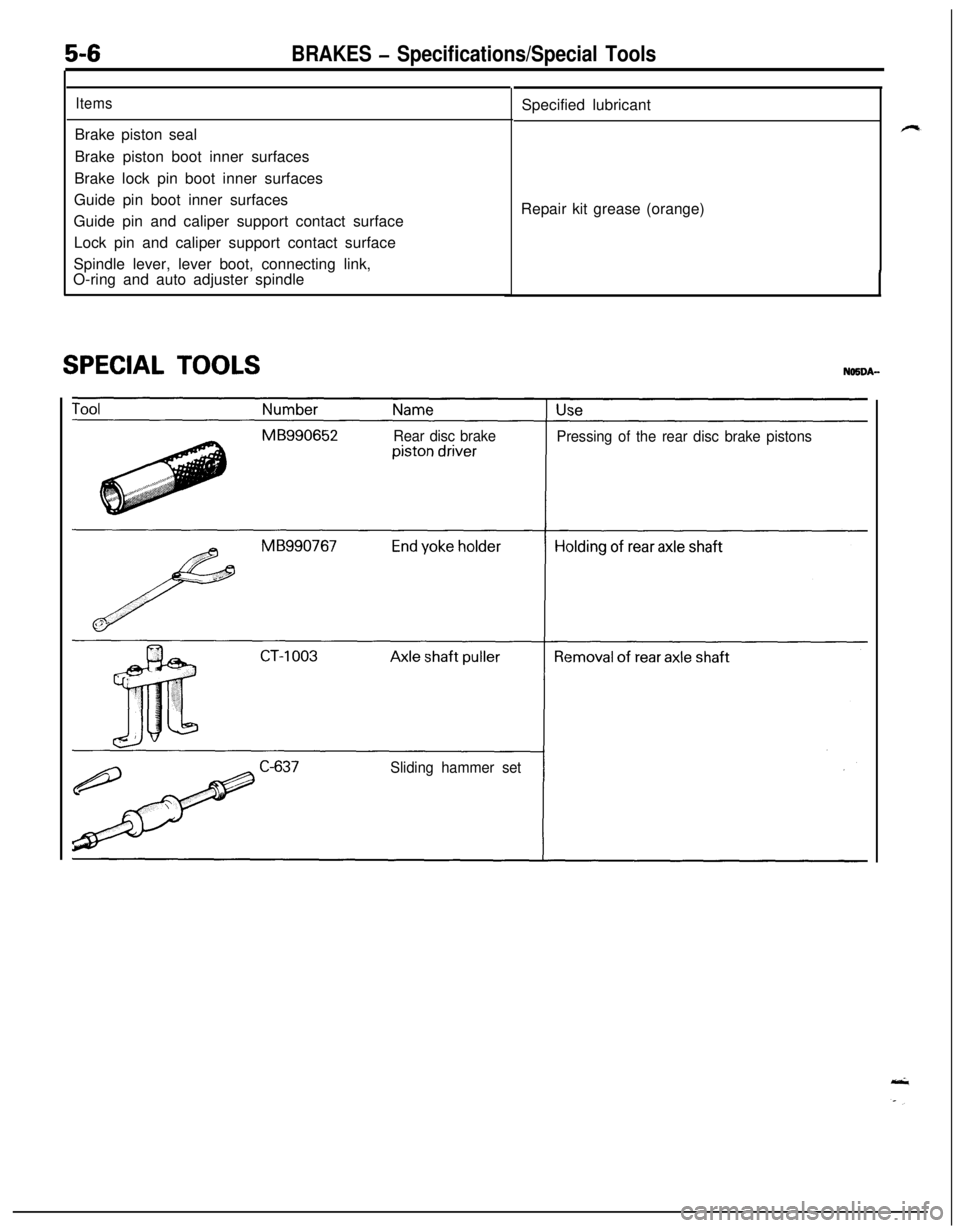
5-6BRAKES - Specifications/Special Tools
ItemsBrake piston seal
Brake piston boot inner surfaces
Brake lock pin boot inner surfaces
Guide pin boot inner surfaces
Guide pin and caliper support contact surface
Lock pin and caliper support contact surface
Spindle lever, lever boot, connecting link,
O-ring and auto adjuster spindle
SPECIAL TOOLSSpecified lubricant
Repair kit grease (orange)
Rear disc brake
Pressing of the rear disc brake pistons
Sliding hammer set
Page 147 of 1216
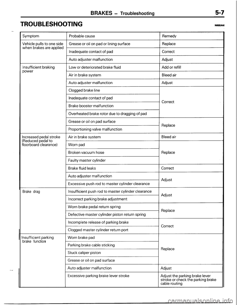
BRAKES - Troubleshooting
TROUBLESHOOTING
-
Brake drag
brake function
Page 148 of 1216

5-8BRAKES - Troubleshooting
Symptom
Scraping or grinding
noise when brakes are
appliedProbable cause
Worn brake pad
Caliper to wheel interference
Cracked brake discRemedy
Replace
Correct or replace
Squealing, groaning orchattering noise when
brakes are appliedDisc brakes-missing or damaged brake pad
anti-
squeak shimReplace
Brake discs and pads worn or scored
Improper lining partsCorrect or replaceDisc brake-burred or rusted calipers
Dirty, greased, contaminated or glazed pad
Incorrect adjustment of brake pedal or booster
push-rodClean or deburrClean or replaceAdjust
Squealing noise when
brakes are not appliedDisc brakes-rusted, stuckLubricate or replace
Loose or extra parts in brakes
Improper positioning of pads in caliperRetighten
Improper installation of support mounting to caliperCorrect
body
Poor return of brake booster or master cylinder
Incorrect adjustment of brake pedal or booster
push-rod
ReplaceAdjust
Groaning, clicking or rat-Stones or foreign material trapped inside wheelRemove stones, etc.
tling noise when brakescovers
are not appliedDisc brakes-failure of shim
ReplaceDisc brakes-loose installation bolt
Retighten
Loose wheel nuts
Incorrect adjustment of brake pedal or booster
push-rodAdjust
Page 149 of 1216

BRAKES - Anti-lock Braking System Troubleshooting5-9
ANTI-LOCK BRAKING SYSTEM
-- TROUBLESHOOTINGNO!JEBAE
PARTICULAR CHARACTERISTICS OF
THE ANTI-LOCK BRAKING SYSTEMModels equipped with the anti-lock braking system
(A.B.S.) may exhibit one or more of the following
characteristics from time to time, but none of these
is abnormal.
(1) A pulsing feeling in the brake pedal, or vibration
of the body or the steering wheel, when the
anti-lock braking system is activated by sudden
braking or by braking on a slippery road surface.Actually, this phenomenon is an indication that
the anti-lock braking system is functioning nor-
mally.(2) When the vehicle speed reaches approximately
6 km/h (4 mph) after the engine is started and
the vehicle starts off (for the first time), a
whining motor noise may be heard from the
engine compartment if the vehicle is traveling in
a quiet place, but this noise is simply the result
of a self-check being made of the anti-lock
braking system operation.
TROUBLESHOOTING METHODSProblems related to the anti-lock braking system
(A.B.S.) can be classified into two general categor-
ies: problems in the electrical system and those in
the hydraulic system.For problems in the electrical system, the
self-diagnosis function is built into the electronic control
unit (E.C.U.) causing the A.B.S. warning light to
illuminate as a warning to the driver.
Problems in the hydraulic system (poor braking,
etc.) can be located in the same way as for ordinary
brakes. There is, however, the necessity to check todetermine whether the problem is related to ordin-
ary brake components or to the components relatedto the A.B.S.
HOW TO USE THE TROUBLESHOOTING
FLOW CHART(1) Using the flow chart, check the ABS warning
light light-up sequence and check the condition
of braking operation.
(2) Following the check chart listed in the remedy
column, perform the checks. There are [Explana-tion] and [Hint] in each check chart. Refer to
them when troubleshooting.
NOTEECU: Electronic control unit
HU: Hydraulic unit
MUT: Multi-use tester
Page 150 of 1216
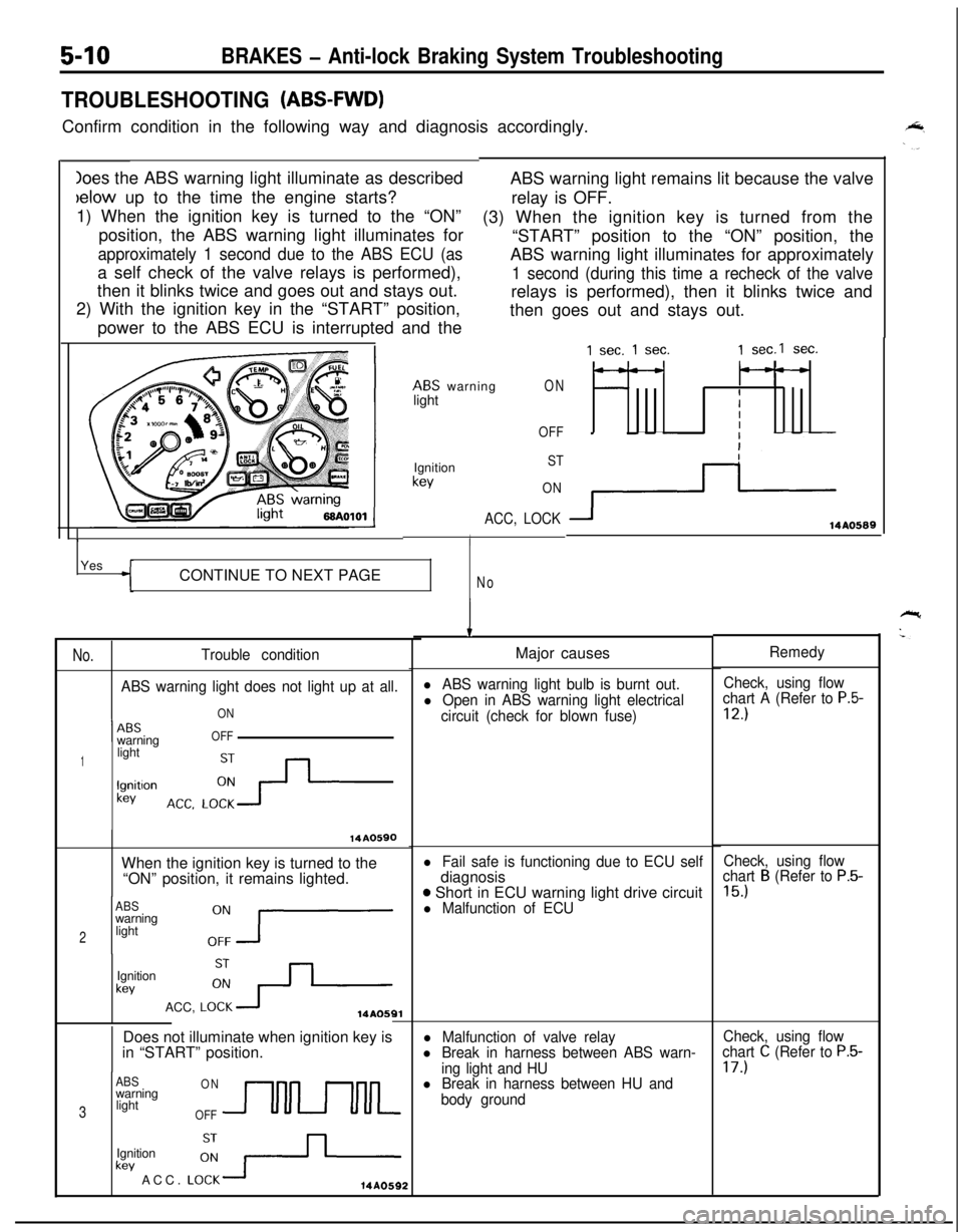
Ioes the ABS warning light illuminate as describedbelow up to the time the engine starts?
1) When the ignition key is turned to the “ON”
position, the ABS warning light illuminates for
approximately 1 second due to the ABS ECU (asa self check of the valve relays is performed),
then it blinks twice and goes out and stays out.
2) With the ignition key in the “START” position,
power to the ABS ECU is interrupted and the
5-10BRAKES - Anti-lock Braking System Troubleshooting
TROUBLESHOOTING (ABS-FWD)Confirm condition in the following way and diagnosis accordingly.
ABS warning light remains lit because the valve
relay is OFF.
(3) When the ignition key is turned from the
“START” position to the “ON” position, the
ABS warning light illuminates for approximately
1 second (during this time a recheck of the valverelays is performed), then it blinks twice and
then goes out and stays out.
ABS warning
lightON
OFF
1Ignition
kev
ST
ON
ACC, LOCK
IYes
CONTINUE TO NEXT PAGE
No
No.Trouble condition
ABS warning light does not light up at all.
ON
1 --ABSwarningOFF
1lightlgnitlon
kev
14A0590When the ignition key is turned to the
“ON” position, it remains lighted.
ABSwarning
2light
Ignition
kevACC,
LO:+14AOSQlDoes not illuminate when ignition key is
in “START” position.
ABSONwarning
3lightOFFUULkev ACC.
LO:-+-Ignition14A0592
1 sec. 1 sec.1 sec.1 sec.
---
IIII
3114AO589
IMajor causes
l ABS warning light bulb is burnt out.Check, using flow
l Open in ABS warning light electricalchart A (Refer to P.5-
circuit (check for blown fuse)12.)
l Fail safe is functioning due to ECU selfdiagnosis
o Short in ECU warning light drive circuitl Malfunction of ECU
l Malfunction of valve relayl Break in harness between ABS warn-
ing light and HU
l Break in harness between HU and
body groundRemedy
Check, using flow
chart
B (Refer to P.5-
15.)
Check, using flow
chart C (Refer to P.5-17.)