MITSUBISHI ECLIPSE 1991 User Guide
Manufacturer: MITSUBISHI, Model Year: 1991, Model line: ECLIPSE, Model: MITSUBISHI ECLIPSE 1991Pages: 1216, PDF Size: 67.42 MB
Page 11 of 1216

INTRODUCTION AND MASTER TROUBLESHOOTING - Vehicle Identification11
Part
Quarter panel
Target area: for original equipment parts: for replacement parts
The label is attached at the
inner side of the parts showr
in the figure.
Hood
The illustration indicates left hand side, outer.
Right hand side is symmetrically opposite.
31A026E
The label is attached at the
inner side of the parts shown
in the figure.
Tailgate
31A0256
The label is attached at the
inner side of the parts shown
in the figure.
31AO260
Page 12 of 1216
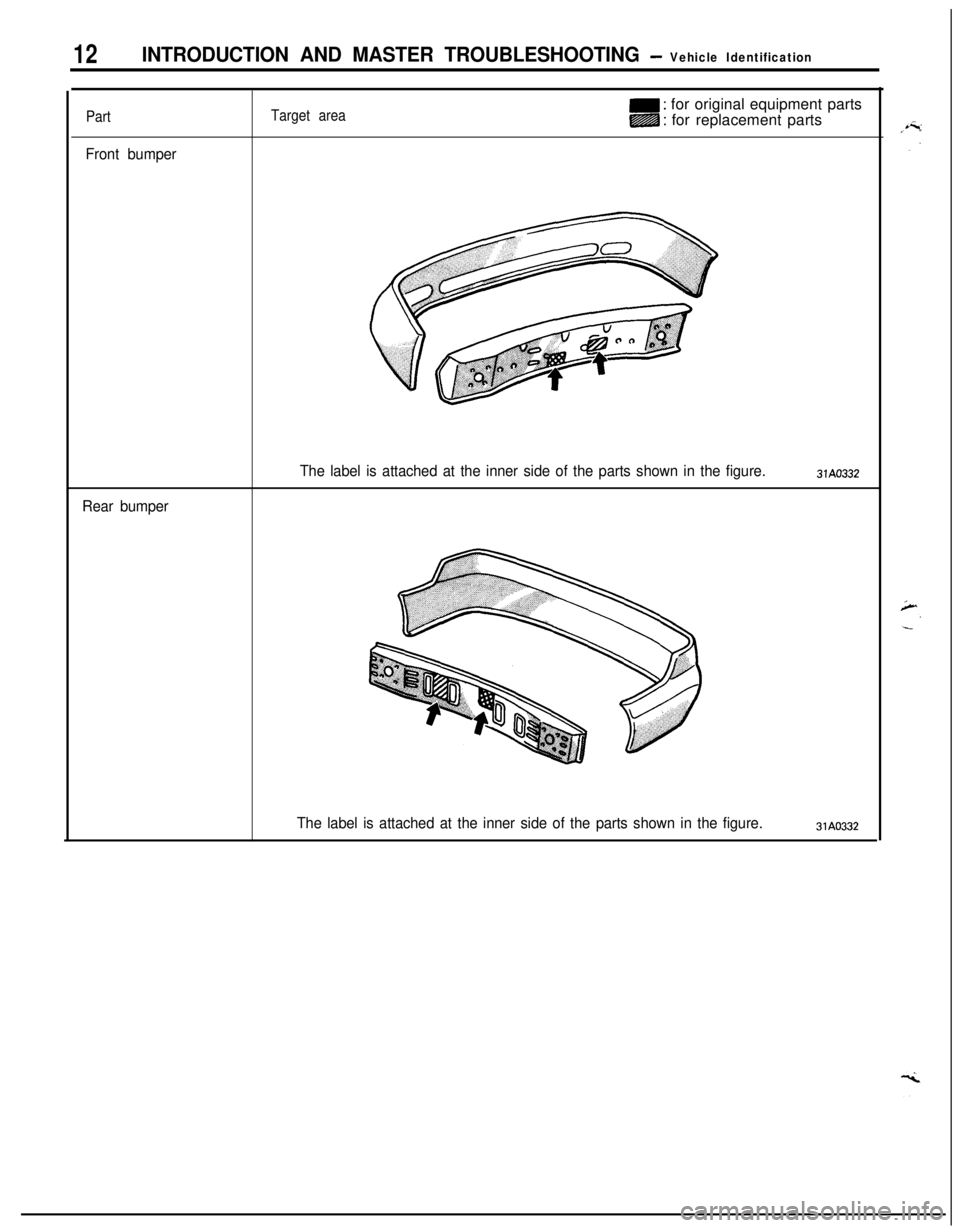
12INTRODUCTION AND MASTER TROUBLESHOOTING - Vehicle Identification
Part
Front bumper
Target aream : for original equipment parts
m : for replacement parts
Rear bumperThe label is attached at the inner side of the parts shown in the figure.
31A0332
The label is attached at the inner side of the parts shown in the figure.31A0332
Page 13 of 1216
INTRODUCTION AND MASTER TROUBLESHOOTING - Precautions befdre Service‘1 S
OOV663OOY192
FOOO 1.
FOOO18
0
OOD511
J7
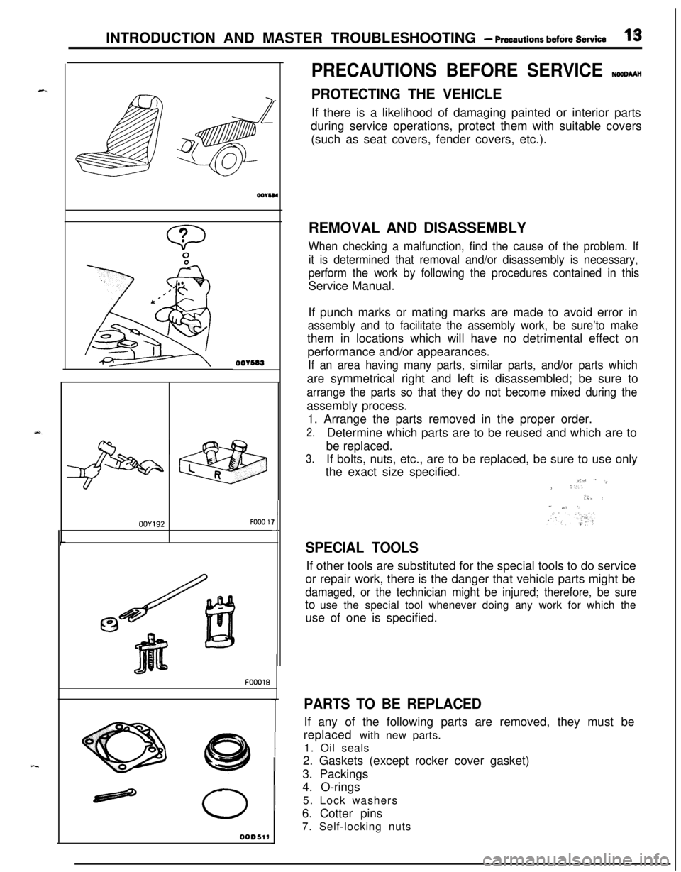
PRECAUTIONS BEFORE SERVICE wxww
PROTECTING THE VEHICLEIf there is a likelihood of damaging painted or interior parts
during service operations, protect them with suitable covers
(such as seat covers, fender covers, etc.).
REMOVAL AND DISASSEMBLY
When checking a malfunction, find the cause of the problem. If
it is determined that removal and/or disassembly is necessary,
perform the work by following the procedures contained in thisService Manual.
If punch marks or mating marks are made to avoid error in
assembly and to facilitate the assembly work, be sure’to makethem in locations which will have no detrimental effect on
performance and/or appearances.
If an area having many parts, similar parts, and/or parts whichare symmetrical right and left is disassembled; be sure to
arrange the parts so that they do not become mixed during theassembly process.
1. Arrange the parts removed in the proper order.
2.Determine which parts are to be reused and which are to
be replaced.
3.If bolts, nuts, etc., are to be replaced, be sure to use only
the exact size specified.
i:c ” -,.> ‘..“i,. i” ,,‘. 5,
SPECIAL TOOLSIf other tools are substituted for the special tools to do service
or repair work, there is the danger that vehicle parts might be
damaged, or the technician might be injured; therefore, be sureto use the special tool whenever doing any work for which the
use of one is specified.
PARTS TO BE REPLACEDIf any of the following parts are removed, they must be
replaced with new parts.
1. Oil seals
2. Gaskets (except rocker cover gasket)
3. Packings
4. O-rings
5. Lock washers
6. Cotter pins
7. Self-locking nuts
Page 14 of 1216
I4INTRODUCTION AND MASTER TROUBLESHOOTING - Precautions before Service
mm (In.1smo59
PARTSWhen replacing parts, use MOPAR genuine parts.
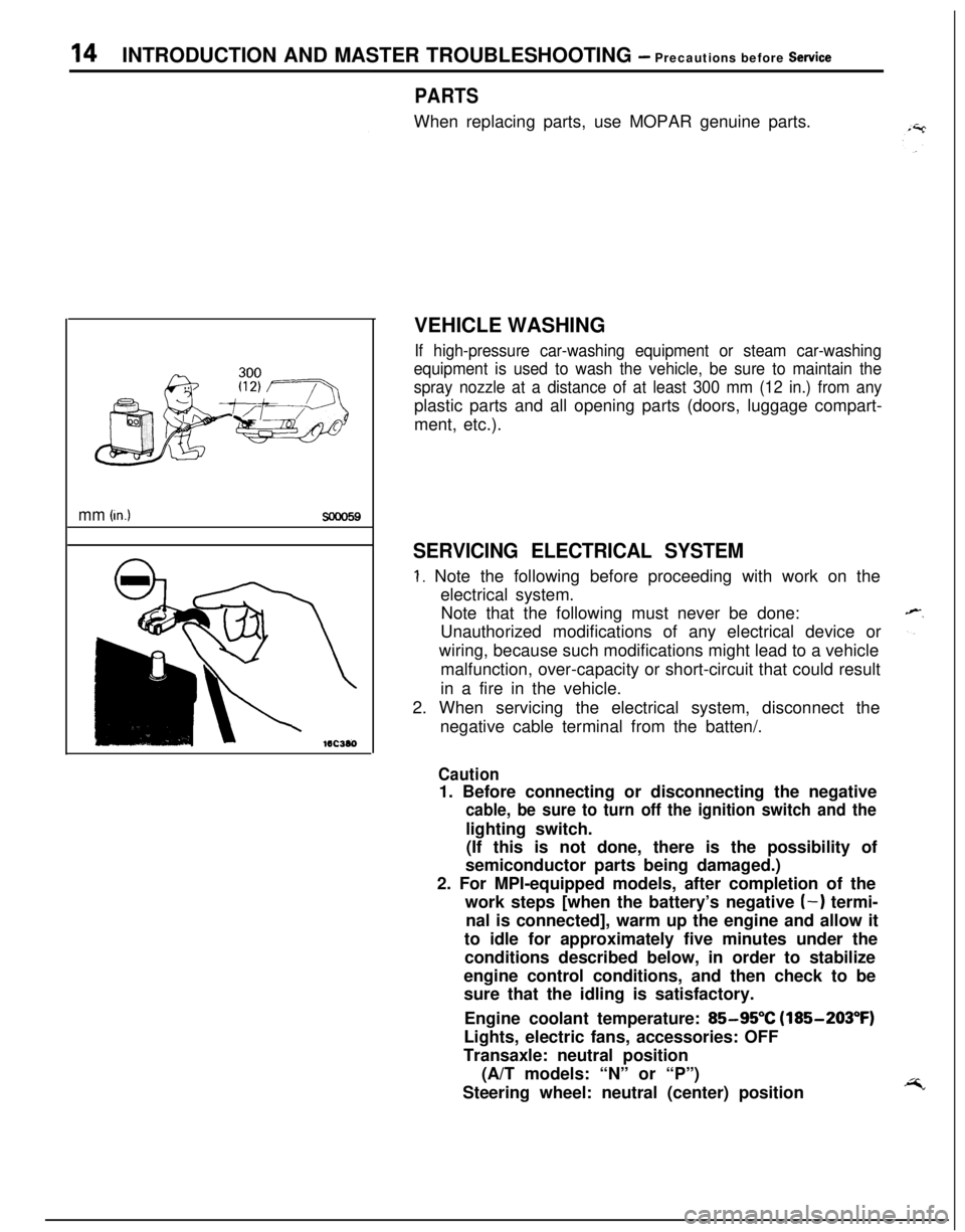
VEHICLE WASHING
If high-pressure car-washing equipment or steam car-washing
equipment is used to wash the vehicle, be sure to maintain the
spray nozzle at a distance of at least 300 mm (12 in.) from anyplastic parts and all opening parts (doors, luggage compart-
ment, etc.).
SERVICING ELECTRICAL SYSTEM
1. Note the following before proceeding with work on the
electrical system.
Note that the following must never be done:
Unauthorized modifications of any electrical device or
wiring, because such modifications might lead to a vehicle
malfunction, over-capacity or short-circuit that could result
in a fire in the vehicle.
2. When servicing the electrical system, disconnect the
negative cable terminal from the batten/.
Caution1. Before connecting or disconnecting the negative
cable, be sure to turn off the ignition switch and thelighting switch.
(If this is not done, there is the possibility of
semiconductor parts being damaged.)
2. For MPI-equipped models, after completion of the
work steps [when the battery’s negative
(-) termi-
nal is connected], warm up the engine and allow it
to idle for approximately five minutes under the
conditions described below, in order to stabilize
engine control conditions, and then check to be
sure that the idling is satisfactory.
Engine coolant temperature:
85-95°C (185-203°F)
Lights, electric fans, accessories: OFF
Transaxle: neutral position
(A/T models: “N” or “P”)
Steering wheel: neutral (center) position
Page 15 of 1216
INTRODUCTION AND MASTER TROUBLESHOOTING - Precautions before Set&e15
F16171
Correct
Cl6385
Cl6367
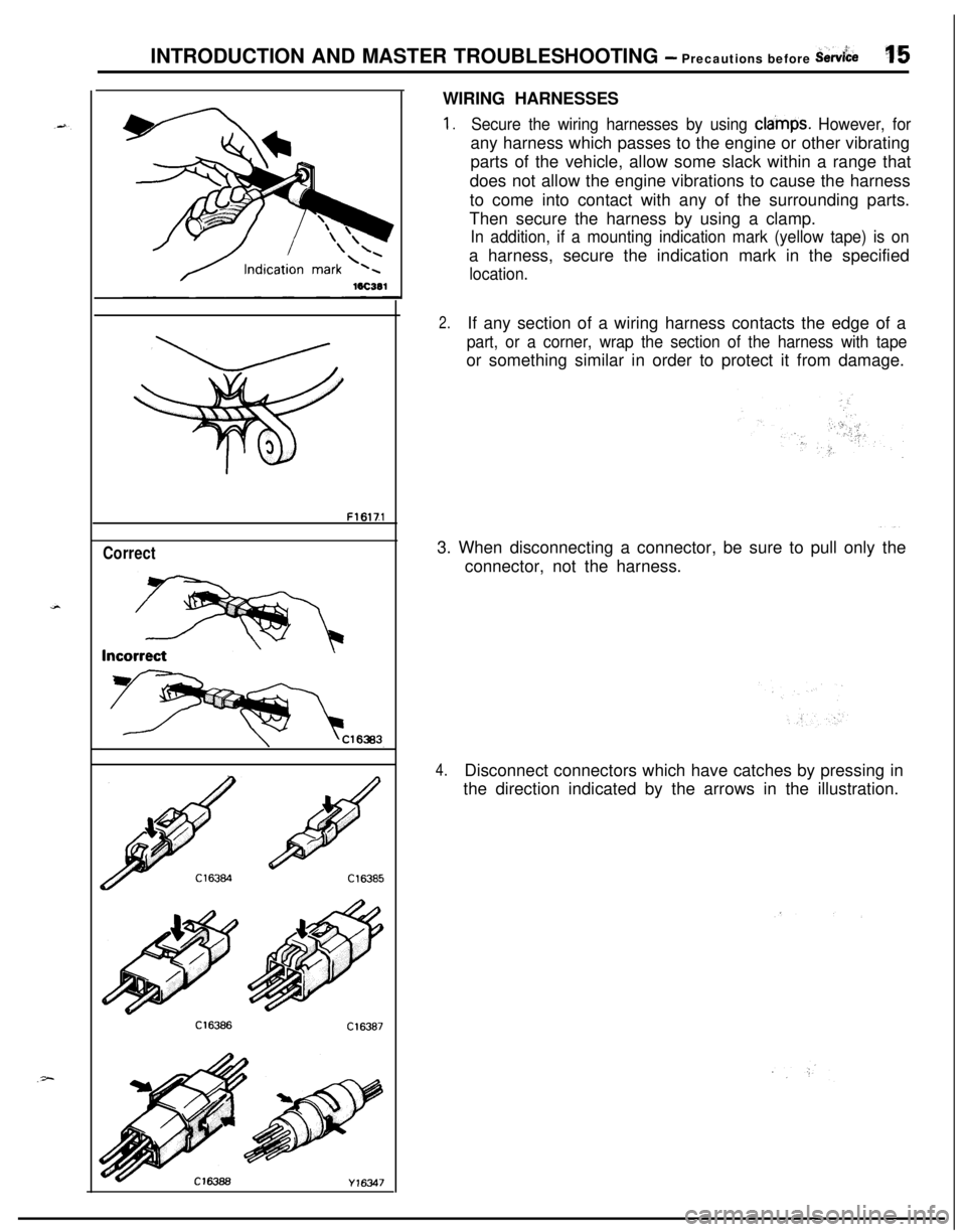
Y16347WIRING HARNESSES
1.Secure the wiring harnesses by using cla’mps. However, forany harness which passes to the engine or other vibrating
parts of the vehicle, allow some slack within a range that
does not allow the engine vibrations to cause the harness
to come into contact with any of the surrounding parts.
Then secure the harness by using a clamp.
In addition, if a mounting indication mark (yellow tape) is ona harness, secure the indication mark in the specified
location.
2.If any section of a wiring harness contacts the edge of a
part, or a corner, wrap the section of the harness with tapeor something similar in order to protect it from damage.
3. When disconnecting a connector, be sure to pull only the
connector, not the harness.
4.Disconnect connectors which have catches by pressing in
the direction indicated by the arrows in the illustration.
Page 16 of 1216
16INTRODUCTION AND MASTER TROUBLESHOOTING - Precautions before Service
Cl6362
OOYSssOOV833
10A15A
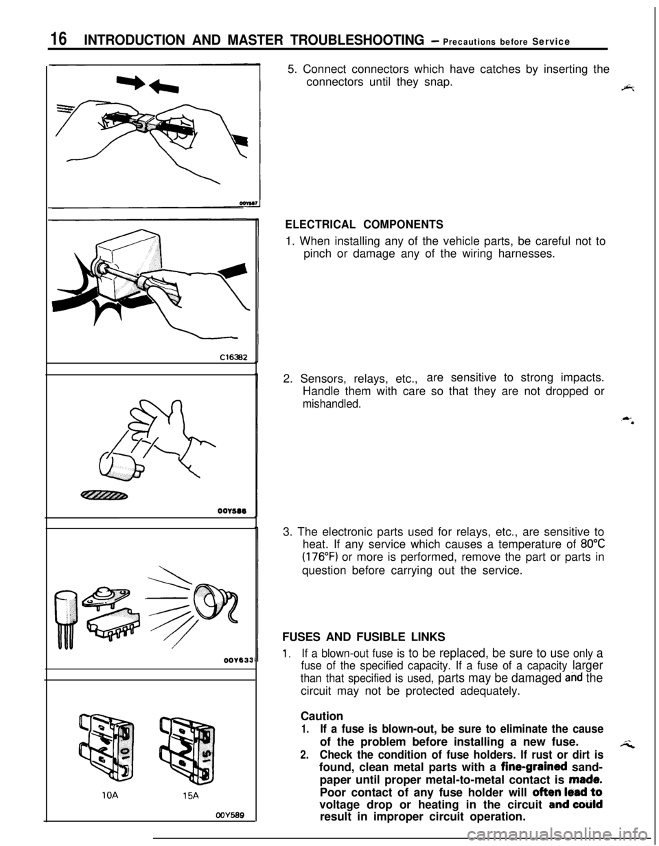
COY5695. Connect connectors which have catches by inserting the
connectors until they snap.
9%
ELECTRICAL COMPONENTS1. When installing any of the vehicle parts, be careful not to
pinch or damage any of the wiring harnesses.
2. Sensors, relays, etc.,are sensitive to strong impacts.
Handle them with care so that they are not dropped or
mishandled.
,**3. The electronic parts used for relays, etc., are sensitive to
heat. If any service which causes a temperature of
80°C
(176°F) or more is performed, remove the part or parts in
question before carrying out the service.
FUSES AND FUSIBLE LINKS
1.If a blown-out fuse is to be replaced, be sure to use only a
fuse of the specified capacity. If a fuse of a capacity larger
than that specified is used, parts may be damaged and thecircuit may not be protected adequately.
Caution
1.If a fuse is blown-out, be sure to eliminate the causeof the problem before installing a new fuse.
;i2.Check the condition of fuse holders. If rust or dirt isfound, clean metal parts with a fine-grained sand-
paper until proper metal-to-metal contact is
made.Poor contact of any fuse holder will
often lead tovoltage drop or heating in the circuit
and colildresult in improper circuit operation.
Page 17 of 1216
INTRODUCTION AND MASTER TROUBLESHOOTING - Precautions before Sew&e‘37
Nominal
sizeSAE
gi:ePermissible current
In engine
Othercompart-areasment
0.3mm2AWG22-5A
0.5
mm2AWG207A13A
0.85
mm’AWG189A17A
1.25
mm2AWG1612A22A
2.0mm2AWG1416A30A
3.0mm’AWG1221A40A
5.0mm2AWG1031A54A
r ‘.
oorsas
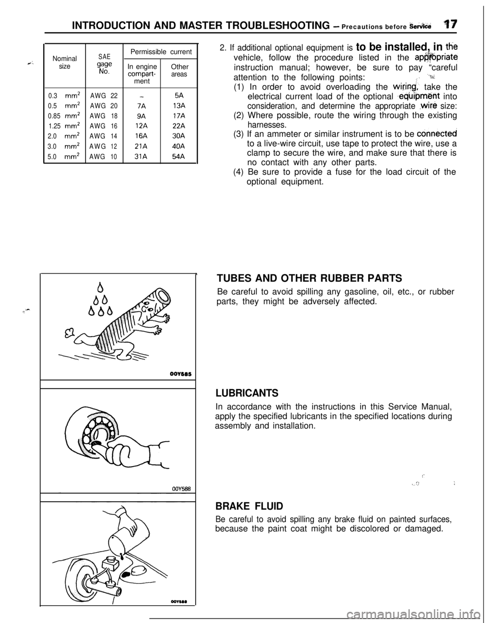
2. If additional optional equipment is to be installed, in ttievehicle, follow the procedure listed in the
ap@@priateinstruction manual; however, be sure to pay “careful
attention to the following points:
“9:(1) In order to avoid overloading the
wiring;’ take the
electrical current load of the optional
,equipment into
consideration, and determine the appropriate .wire size:(2) Where possible, route the wiring through the existing
harnesses.(3) If an ammeter or similar instrument is to be
connectedto a live-wire circuit, use tape to protect the wire, use a
clamp to secure the wire, and make sure that there is
no contact with any other parts.
(4) Be sure to provide a fuse for the load circuit of the
optional equipment.
TUBES AND OTHER RUBBER PARTS
Be careful to avoid spilling any gasoline, oil, etc., or rubber
parts, they might be adversely affected.
LUBRICANTSIn accordance with the instructions in this Service Manual,
apply the specified lubricants in the specified locations during
assembly and installation.
!’IV/ :>,I
BRAKE FLUID
Be careful to avoid spilling any brake fluid on painted surfaces,because the paint coat might be discolored or damaged.
Page 18 of 1216
18INTRODUCTION AND MASTER TROUBLESHOOTING - Precautions b&ire Service
DOING SERVICE WORK IN GROUPS OF VO’bRMORE TECHNICIANS
.-I-7.IIf the service work is to be done by two or more technicians
working together, extra caution must be taken.
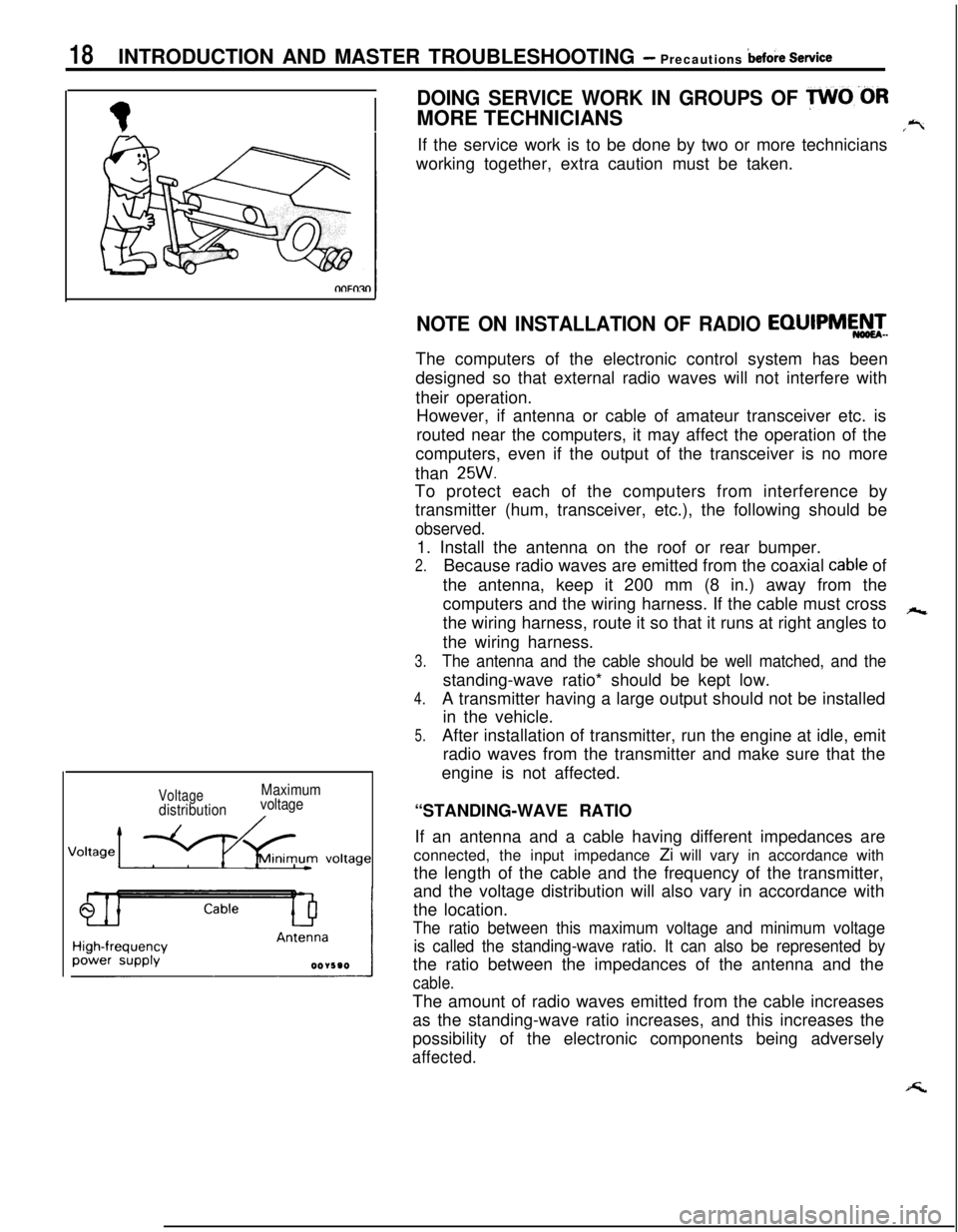
VoltagedistributionMaximum
voltage
NOTE ON INSTALLATION OF RADIO EQIJIPMEATeThe computers of the electronic control system has been
designed so that external radio waves will not interfere with
their operation.
However, if antenna or cable of amateur transceiver etc. is
routed near the computers, it may affect the operation of the
computers, even if the output of the transceiver is no more
than
25W.To protect each of the computers from interference by
transmitter (hum, transceiver, etc.), the following should be
observed.1. Install the antenna on the roof or rear bumper.
2.Because radio waves are emitted from the coaxial cable of
the antenna, keep it 200 mm (8 in.) away from the
computers and the wiring harness. If the cable must cross
hthe wiring harness, route it so that it runs at right angles to
the wiring harness.
3.The antenna and the cable should be well matched, and thestanding-wave ratio* should be kept low.
4.A transmitter having a large output should not be installed
in the vehicle.
5.After installation of transmitter, run the engine at idle, emit
radio waves from the transmitter and make sure that the
engine is not affected.
“STANDING-WAVE RATIO
If an antenna and a cable having different impedances are
connected, the input impedance Zi will vary in accordance with
the length of the cable and the frequency of the transmitter,
and the voltage distribution will also vary in accordance with
the location.
The ratio between this maximum voltage and minimum voltage
is called the standing-wave ratio. It can also be represented bythe ratio between the impedances of the antenna and the
cable.The amount of radio waves emitted from the cable increases
as the standing-wave ratio increases, and this increases the
possibility of the electronic components being adversely
affected.
Page 19 of 1216
c
--INTRODUCTION AND MASTER
TROUBLESHOOTtNG - Towing and Hoi&gT9
I-
Sling type
Wheel lift type
Flat bed type
iling type
Vheel lift type
lat bed type
TOWING AND HOISTINGNOOGA-
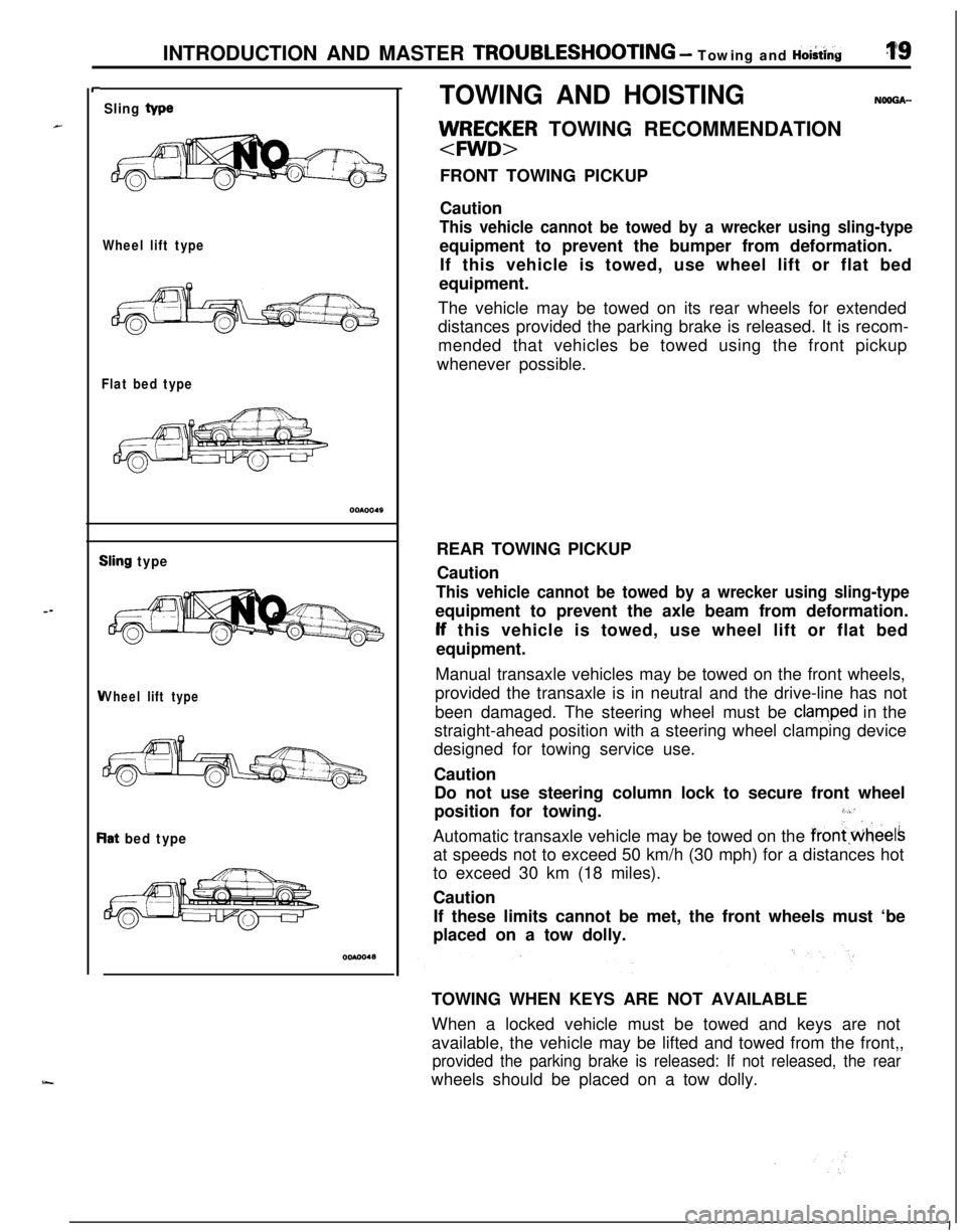
llJ/RE;~R TOWING RECOMMENDATION
FRONT TOWING PICKUP
Caution
This vehicle cannot be towed by a wrecker using sling-typeequipment to prevent the bumper from deformation.
If this vehicle is towed, use wheel lift or flat bed
equipment.
The vehicle may be towed on its rear wheels for extended
distances provided the parking brake is released. It is recom-
mended that vehicles be towed using the front pickup
whenever possible.
REAR TOWING PICKUP
Caution
This vehicle cannot be towed by a wrecker using sling-typeequipment to prevent the axle beam from deformation.lf this vehicle is towed, use wheel lift or flat bed
equipment.
Manual transaxle vehicles may be towed on the front wheels,
provided the transaxle is in neutral and the drive-line has not
been damaged. The steering wheel must be
clam,ped in the
straight-ahead position with a steering wheel clamping device
designed for towing service use.
Caution
Do not use steering column lock to secure front wheel
position for towing.
3,“’Automatic transaxle vehicle may be towed on the
frontwheelsat speeds not to exceed 50 km/h (30 mph) for a distances hot
to exceed 30 km (18 miles).
Caution
If these limits cannot be met, the front wheels must ‘be
placed on a tow dolly.
TOWING WHEN KEYS ARE NOT AVAILABLE
When a locked vehicle must be towed and keys are not
available, the vehicle may be lifted and towed from the front,,
provided the parking brake is released: If not released, the rearwheels should be placed on a tow dolly.
I
Page 20 of 1216
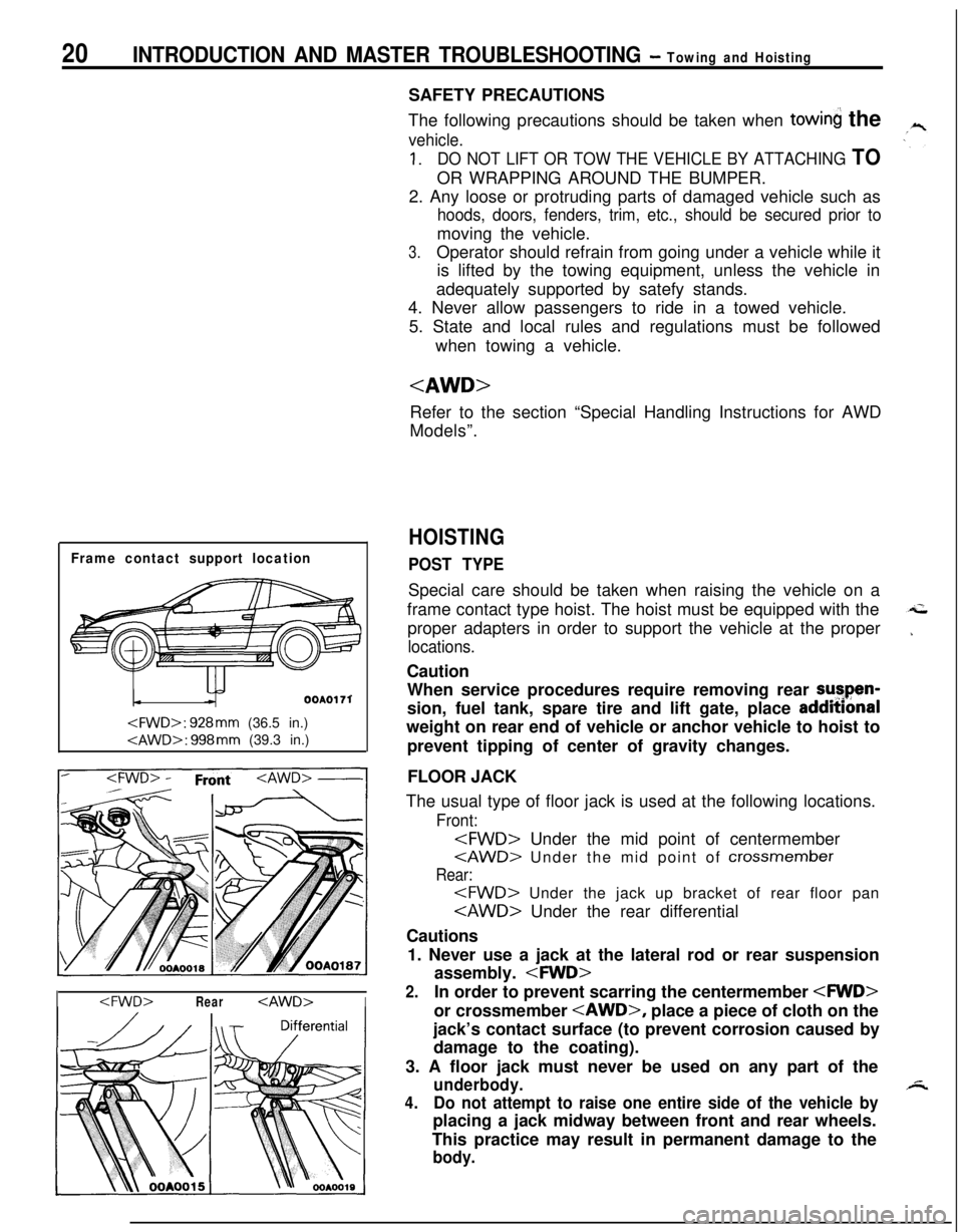
20INTRODUCTION AND MASTER TROUBLESHOOTING - Towing and Hoisting
Frame contact support location
OOAOI 71
I
The following precautions should be taken when
towin the
vehicle.
1.DO NOT LIFT OR TOW THE VEHICLE BY ATTACHING TOOR WRAPPING AROUND THE BUMPER.
2. Any loose or protruding parts of damaged vehicle such as
hoods, doors, fenders, trim, etc., should be secured prior tomoving the vehicle.
3.Operator should refrain from going under a vehicle while it
is lifted by the towing equipment, unless the vehicle in
adequately supported by satefy stands.
4. Never allow passengers to ride in a towed vehicle.
5. State and local rules and regulations must be followed
when towing a vehicle.
Refer to the section “Special Handling Instructions for AWD
Models”.
HOISTING
POST TYPESpecial care should be taken when raising the vehicle on a
frame contact type hoist. The hoist must be equipped with the
proper adapters in order to support the vehicle at the proper
locations.Caution
When service procedures require removing rear sutpen-
sion, fuel tank, spare tire and lift gate, place addmonal
weight on rear end of vehicle or anchor vehicle to hoist to
prevent tipping of center of gravity changes.
FLOOR JACK
The usual type of floor jack is used at the following locations.
Front:
Rear:
Cautions
1. Never use a jack at the lateral rod or rear suspension
assembly.
2.In order to prevent scarring the centermember
jack’s contact surface (to prevent corrosion caused by
damage to the coating).
3. A floor jack must never be used on any part of the
underbody.
4.Do not attempt to raise one entire side of the vehicle byplacing a jack midway between front and rear wheels.
This practice may result in permanent damage to the
body.