MITSUBISHI ECLIPSE 1991 Owner's Manual
Manufacturer: MITSUBISHI, Model Year: 1991, Model line: ECLIPSE, Model: MITSUBISHI ECLIPSE 1991Pages: 1216, PDF Size: 67.42 MB
Page 21 of 1216
--
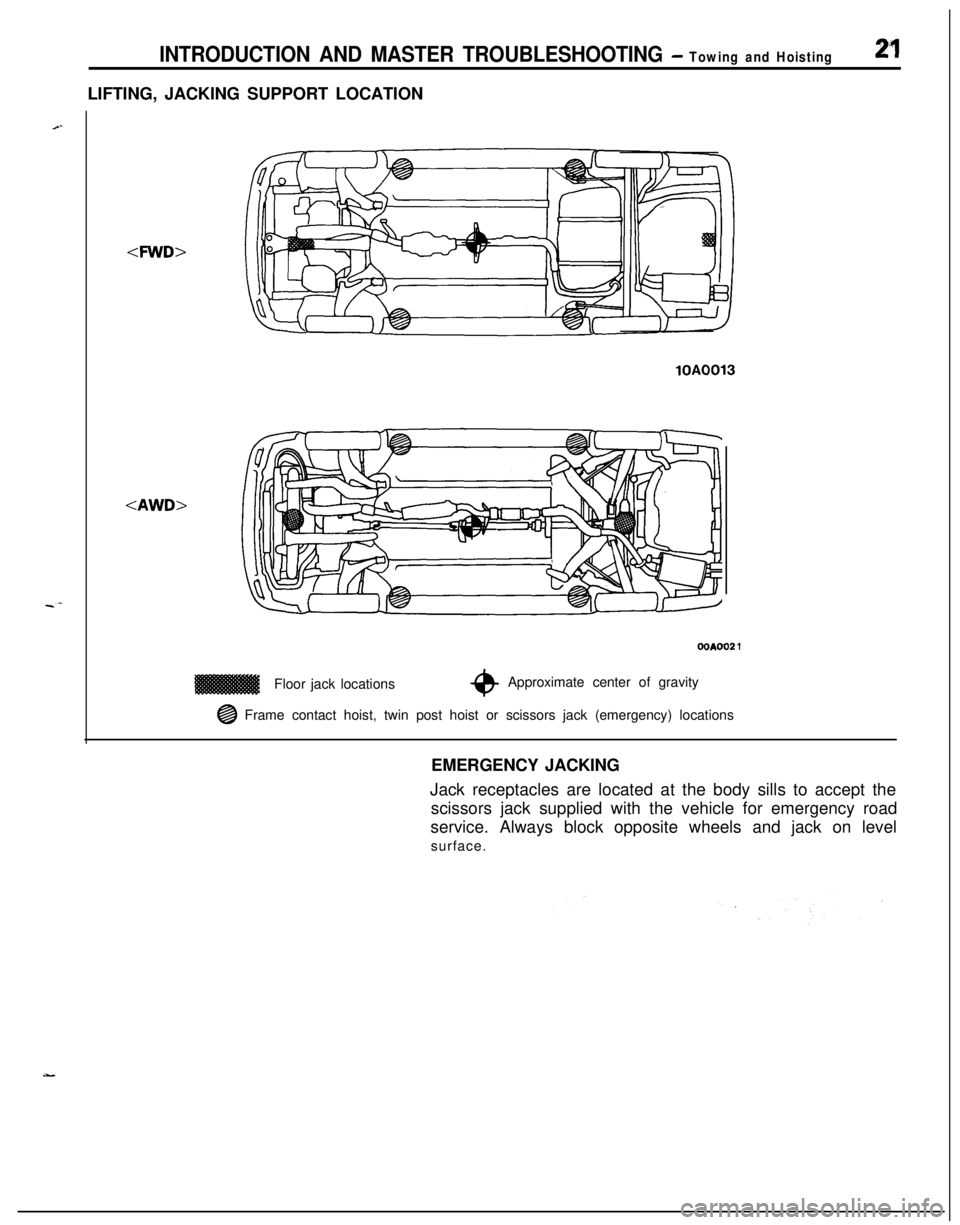
INTRODUCTION AND MASTER TROUBLESHOOTING - Towing and Hoisting2”1LIFTING, JACKING SUPPORT LOCATION
-4WD>
lOAFloor jack locations
OOAOO2 1
*Approximate center of gravity
@ Frame contact hoist, twin post hoist or scissors jack (emergency) locations
EMERGENCY JACKING
Jack receptacles are located at the body sills to accept the
scissors jack supplied with the vehicle for emergency road
service. Always block opposite wheels and jack on level
surface.
Page 22 of 1216
22 INTRODUCTION AND MASTER TROUBLESHOOTING - %%c%:k! ‘nstructions
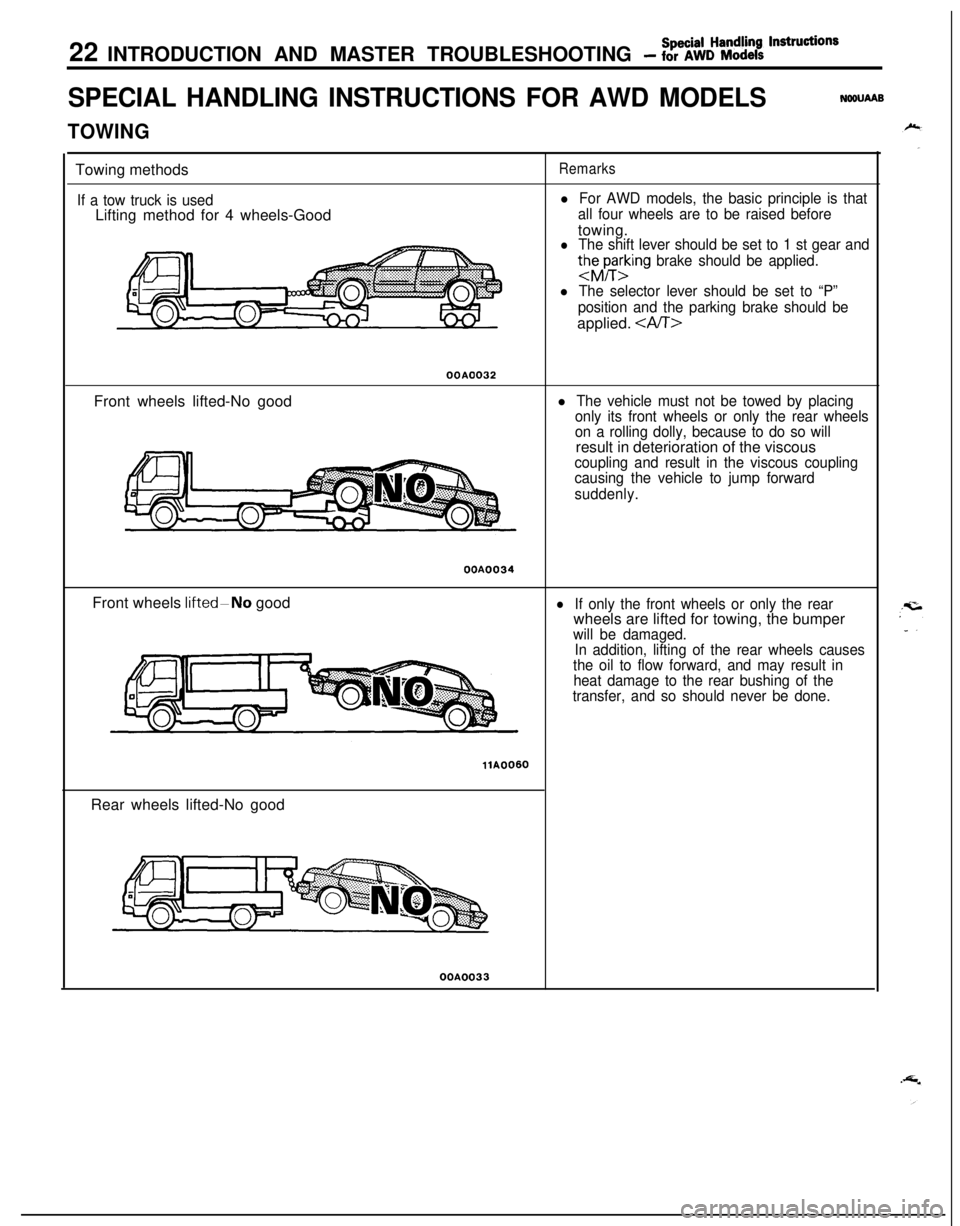
SPECIAL HANDLING INSTRUCTIONS FOR AWD MODELSNWUAAB
TOWINGTowing methods
If a tow truck is usedLifting method for 4 wheels-Good
Remarks
l For AWD models, the basic principle is that
all four wheels are to be raised beforetowing.
l The shift lever should be set to 1 st gear and
thhrting brake should be applied.
l The selector lever should be set to “P”
position and the parking brake should beapplied.
OOAO032Front wheels lifted-No good
l The vehicle must not be towed by placing
only its front wheels or only the rear wheels
on a rolling dolly, because to do so willresult in deterioration of the viscous
coupling and result in the viscous coupling
causing the vehicle to jump forward
suddenly.OOA0034
Front wheels
IifteddNo goodlIf only the front wheels or only the rearwheels are lifted for towing, the bumper
will be damaged.
In addition, lifting of the rear wheels causes
the oil to flow forward, and may result in
heat damage to the rear bushing of the
transfer, and so should never be done.
llA0060Rear wheels lifted-No goodOOA0033
Page 23 of 1216
Special Handling lnstruction~INTRODUCTION AND MASTER TROUBLESHOOTING - for AWD Models23
7T
TFree roller
00P0030
T&a
TAxle standOOPOO37
Front tie-down bracket
16PO209
14A0198
OOPO036
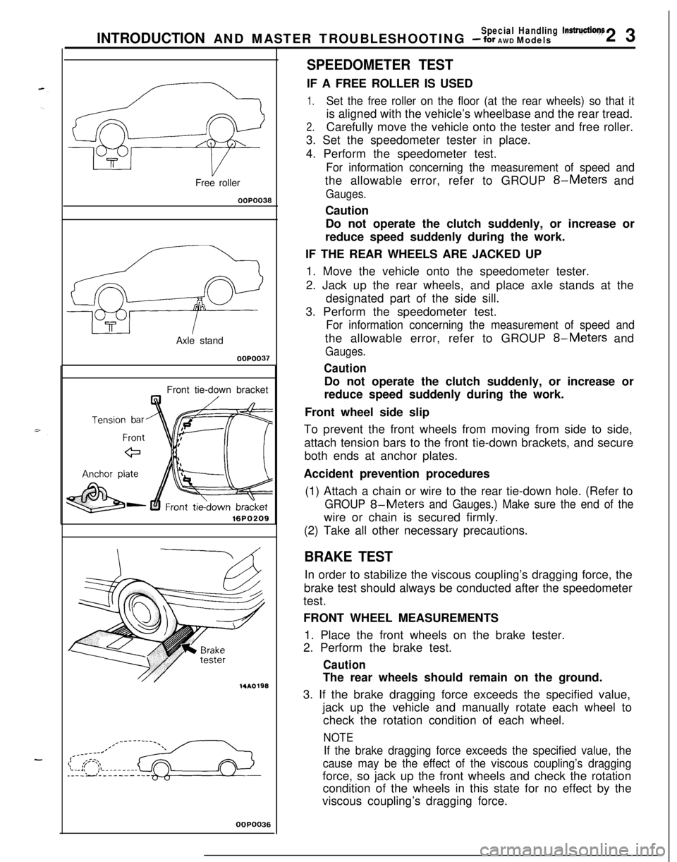
SPEEDOMETER TESTIF A FREE ROLLER IS USED
1.Set the free roller on the floor (at the rear wheels) so that itis aligned with the vehicle’s wheelbase and the rear tread.
2.Carefully move the vehicle onto the tester and free roller.
3. Set the speedometer tester in place.
4. Perform the speedometer test.
For information concerning the measurement of speed andthe allowable error, refer to GROUP
8-Meters and
Gauges.Caution
Do not operate the clutch suddenly, or increase or
reduce speed suddenly during the work.
IF THE REAR WHEELS ARE JACKED UP
1. Move the vehicle onto the speedometer tester.
2. Jack up the rear wheels, and place axle stands at the
designated part of the side sill.
3. Perform the speedometer test.
For information concerning the measurement of speed andthe allowable error, refer to GROUP
8-Meters and
Gauges.
CautionDo not operate the clutch suddenly, or increase or
reduce speed suddenly during the work.
Front wheel side slip
To prevent the front wheels from moving from side to side,
attach tension bars to the front tie-down brackets, and secure
both ends at anchor plates.
Accident prevention procedures
(1) Attach a chain or wire to the rear tie-down hole. (Refer to
GROUP 8-Meters and Gauges.) Make sure the end of thewire or chain is secured firmly.
(2) Take all other necessary precautions.
BRAKE TESTIn order to stabilize the viscous coupling’s dragging force, the
brake test should always be conducted after the speedometer
test.
FRONT WHEEL MEASUREMENTS
1. Place the front wheels on the brake tester.
2. Perform the brake test.
CautionThe rear wheels should remain on the ground.
3. If the brake dragging force exceeds the specified value,
jack up the vehicle and manually rotate each wheel to
check the rotation condition of each wheel.
NOTE
If the brake dragging force exceeds the specified value, the
cause may be the effect of the viscous coupling’s draggingforce, so jack up the front wheels and check the rotation
condition of the wheels in this state for no effect by the
viscous coupling’s dragging force.
Page 24 of 1216
24 INTRODUCTION AND MASTER TROUBLESHOOTING - fSo%k%:~~it’ndrU~ionsREAR WHEEL MEASUREMENTS
After placing the rear wheels on the brake tester, follow the
same procedures as for the front wheel measurements.
,’
~.Braking force of AWD models with VCU
Balancing
machine
Pick-up stand
WA0024
Braking force
EachwheelLeft/right
sumLeft/right
differenceAt
90kg (19860% or more ofIbs.) pedal de-front axle weightpression force
Rear wheels: 330
kg (727 Ibs.) or more8% or less of axle weight
TotalAt 90kg (198830 kg (1,829 Ibs.)
Ibs.) pedal de-or more*pression force
* About 20 kg (44 Ibs.) of force by viscosity torque has been
added.
or...
I
Braking-stop distanceAt primary velocity of 50 km/h
(31 mph): Within 16.0m (52.5 ft.)
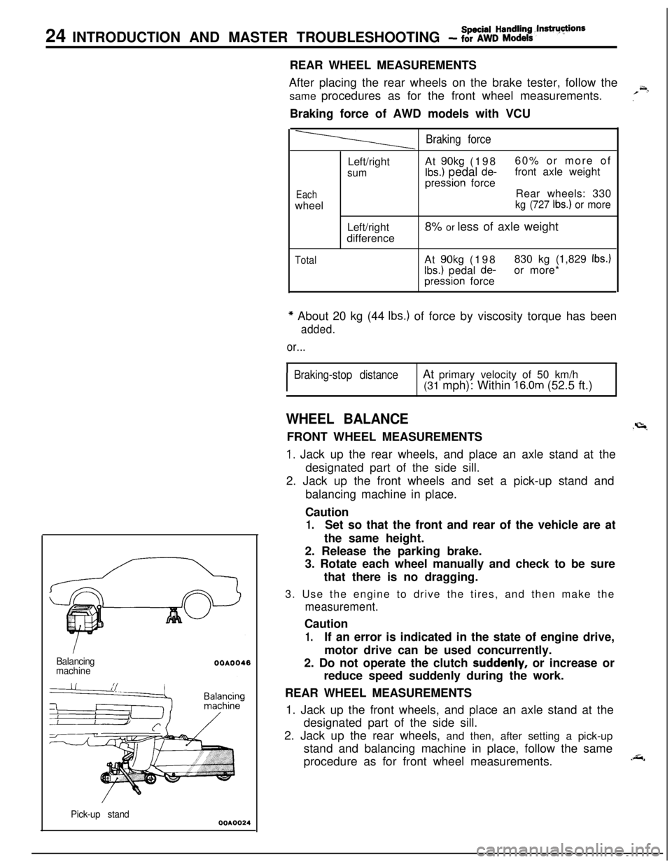
WHEEL BALANCE.r=lFRONT WHEEL MEASUREMENTS
1. Jack up the rear wheels, and place an axle stand at the
designated part of the side sill.
2. Jack up the front wheels and set a pick-up stand and
balancing machine in place.
Caution
1.Set so that the front and rear of the vehicle are at
the same height.
2. Release the parking brake.
3. Rotate each wheel manually and check to be sure
that there is no dragging.
3. Use the engine to drive the tires, and then make the
measurement.Caution
1.If an error is indicated in the state of engine drive,
motor drive can be used concurrently.
2. Do not operate the clutch
suddenly, or increase or
reduce speed suddenly during the work.
REAR WHEEL MEASUREMENTS
1. Jack up the front wheels, and place an axle stand at the
designated part of the side sill.
2. Jack up the rear wheels, and then, after setting a pick-up
stand and balancing machine in place, follow the same
procedure as for front wheel measurements.
.&,
Page 25 of 1216
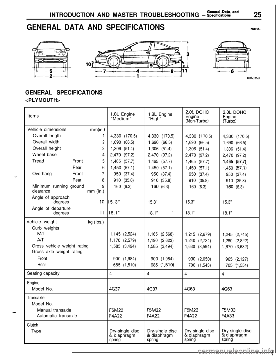
INTRODUCTION AND MASTER TROUBLESHOOTING - :;k%ii::& and25
GENERAL DATA AND SPECIFICATIONSNOOHA-
OOAOl59
GENERAL SPECIFICATIONS
z-
A-l
.8L Engine1.8L Engine2.0L DOHC2.0L DOHCItems“Medium”“High”~%n?urbo):Tz%$
Vehicle dimensions
mm(in.)Overall length
14,330(170.5)4,330(170.5)4,330(I 70.5)4,330(170.5)Overall width
21,690(66.5)1,690(66.5)
1,690
(66.5)
1,690(66.5)Overall height
31,306(51.4)1,306(51.4)1,306(51.4)
1,306(51.4)Wheel base
4
2,470(97.2)2,470(97.2)2,470(97.2)2,470(97.2)Tread Front
5
1,465(57.7)
1,465(57.7)
1,465
(57.7)1,465(57.7)
Rear6
1,450(57.1)1,450(57.1)1,450(57.1)1,450(57:l i
Overhang Front
7950(37.4)950(37.4)950(37.4)
950(37.4)
Rear
8
910(35.8)910(35.8)910(35.8)910(35.8)Minimum running ground
9
160(6.3)160(6.3)
160(6.3)160(6.3)clearancemm (in.)
Angle of approach
degrees10 15.3”15.3”15.3”
15.3”Angle of departure
degrees11 18.1”
18.1” ’18.1“
18.1”Vehicle weight
kg (Ibs.)
Curb weights
M/T
1,145(2,524)
1,165(2,568)
1,215
(2,679)
1,245(2,745)
AIT1 ,I 70(2,579)
1,190(2,623)
1,240
(2,734)
1,280(2,822)Gross vehicle weight rating
1,585(3,494)1,585(3,494)
1,630
(3,594)‘I ,670(3,682)Gross axle weight rating
Front
900(1,984)900(1,984)930(2,050)965(2,127)
Rear
685(1,510)685(1,510)
700
(1,543)705‘(1,554)Seating capacity
4
444
EngineModel No.
4G3746374G634G63
TransaxleModel No.
Manual transaxle
F5M22F5M22F5M22F5M33Automatic transaxle
F4A22F4A22F4A22F4A33
Clutch
TypeDry-single discDry-single discDry-single discDry-single disc& diaphragm& diaphragm& diaphragm& diaphragm
springspringspringspring
Page 26 of 1216
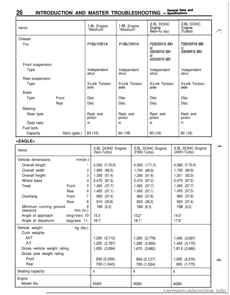
26INTRODUCTION AND MASTER TROUBLESHOOTING - :;:%:a=and
Items
Chassis
TireFront suspension
TypeRear suspension
We
Brake
Type
SteeringGear typeFront
RearGear ratio
Fuel tank
Capacityliters (gals.)
1.8L Engine
“Medium”Pl85/70R14
PI 85/70Rl4
Independent
strut
Independentstrut
3l\Fk Torsion&k-k Torsion
Disc
DiscDisc
Disc
Rack and
pinion
03
Rack and
pinion
cn60 (16)
60
(16)
ItemsVehicle dimensions
mm(in.)Overall length
1Overall width
2Overall height
3Wheel base
4
TreadFront5
Rear6
OverhangFront7
Rear8Minimum running ground
9
clearancemm (in.)
Angle of approachdegrees
10Angle of departure
degrees 11
Vehicle weight
kg (Ibs.)Curb weightsMiT
Al-rGross vehicle weight rating
Gross axle weight rating
Front
RearSeating capacity
EngineModel No.
1.8L Engine
“Medium”2.0L DOHC
Kr%n?u rbo)
P205/55Rl6 89H
;;5/55R16 89V%55R16
88V
Independentstrut
zx;;k Torsion
Disc
Disc
Rack and
pinion
co60 (16)
2.0L DOHC
#b”;
P205/55Rl6 89
or
205155R16 88V
Independentstrut
3Lnk Torsion
Disc
Disc
Rack and
pinion
co
60 (16)
2.0L DOHC Engine(Non-Turbo)
4,330(I 70.5)
1,690(66.5)
1,306(51.4)
2,470(97.2)
1,465(57.7)
1,450(57.1)
950(37.4)
910(35.8)
160(6.3)
15.3
18.1”
1,230 (2,712)
1,255 (2,767)
1,630 (3,594)930 (2,050)
700 (1,543)
4
4G63
2.0L DOHC Engine
(FWD-Turbo)
4,350(171.3)
1,700(66.9)
1,306(51.4)
2,470(97.2)
1,465(57.7)
1,450(57.1)
960(37.8)
920(36.2)
160(6.3)
13.2”
18.1”
1,260 (2,778)
1,295 (2,855)
1,670 (3,682)965 (2,127)
705 (1,554)
1
4G63
2.0L DOHC Engine
(AWD-Turbo)
4,380(I 72.4)
1,700(66.9)
1,321(52.0)
2,470(97.2)
1,465(57.7)
1,455(57.3)
960(37.8)
950(37.4)
158(6.2)
14.0”
17.6”
1,405 (3,097)
1,440 (3,175)
I,81 0 (3,990)
1,005 (2,216)
805 (1,775)
4
4G63
Page 27 of 1216
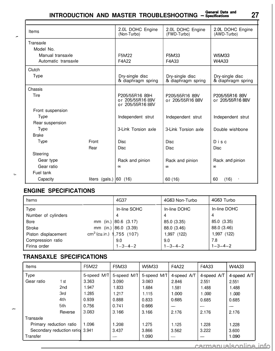
INTRODUCTION AND MASTER TROUBLESHOOTING - f~EEaZ% acld27
=r
9..
Items
TransaxleModel No.
Manual transaxle
Automatic transaxle
Clutch
Type
Chassis
TireFront suspension
TypeRear suspension
Type
Brake
Type
SteeringGear type
Gear ratio
Fuel tank
Capacity
2.0L DOHC Engine2.0L DOHC Engine2.0L DOHC Engine
(Non-Turbo)(FWD-Turbo)(AWD-Turbo)
F5M22F5M33W5M33
F4A22F4A33W4A33Dry-single disc
Dry-single discDry-single disc& diaphragm spring& diaphragm spring& diaphragm spring
P205/55R16 89HP205155R16 89VP205/55R16 89Vor 205/55R16 89Vor 205/55R16 88Vor 205/55R16 88Vor 205/55R16 88VIndependent strut
Independent strutIndependent strut
3-Link Torsion axle3-Link Torsion axleDouble wishbone
Front
Disc
DiscDisc
RearDisc
DiscDiscRack and pinion
Rack and pinionRack
,and pinion
03coccliters (gals.) 60 (16)
60 (16)60 (16)
)
ENGINE SPECIFICATIONS
Items4G374G63 Non-Turbo4G63 Turbo
TypeIn-line SOHCIn-line DOHCIn-line DOHC
Number of cylinders
444
Boremm (in.) 80.6 (3.17)
85.0 (3.35)85.0 (3.35)
Strokemm (in.) 86.0 (3.39)
88.0 (3.46)88.0 (3.46)
Piston displacement
cm3 (cu.in.) 1,755 (107)1,997 (122)1,997 (122)Compression ratio
9.09.07.8Firina order
1-3-4-21-3-4-21-3-4-2
TRANSAXLE SPECIFICATIONS
ItemsF5M22F5M33W5M33F4A22F4A33W4A33
TypeGear ratio
1 st
2nd
3rd
4th
5th
Reverse
TransaxlePrimary reduction ratio
Secondary reduction
ratio
Transfer
5-speed M/T5-speed M/T
3.363
3.090
1.947
1.833
1.285
1.217
0.939
0.888
0.756
0.741
3.0833.166
5speed M/T4-speed A/T4-speed AIT
3.083
2.8462.551
1.6841.5811.488
1.115
1.0001 .ooo
0.8330.6850.685
0.666--
3.166
2.1762.176
Qspeed AIT
2.551
1.488
1 .ooo
0.685
-
2.176
1.096
3.9411.2081.275
1.1251.2281.228
3.4373.866
3.5623.222
3.600
-1.090--1.090
Page 28 of 1216
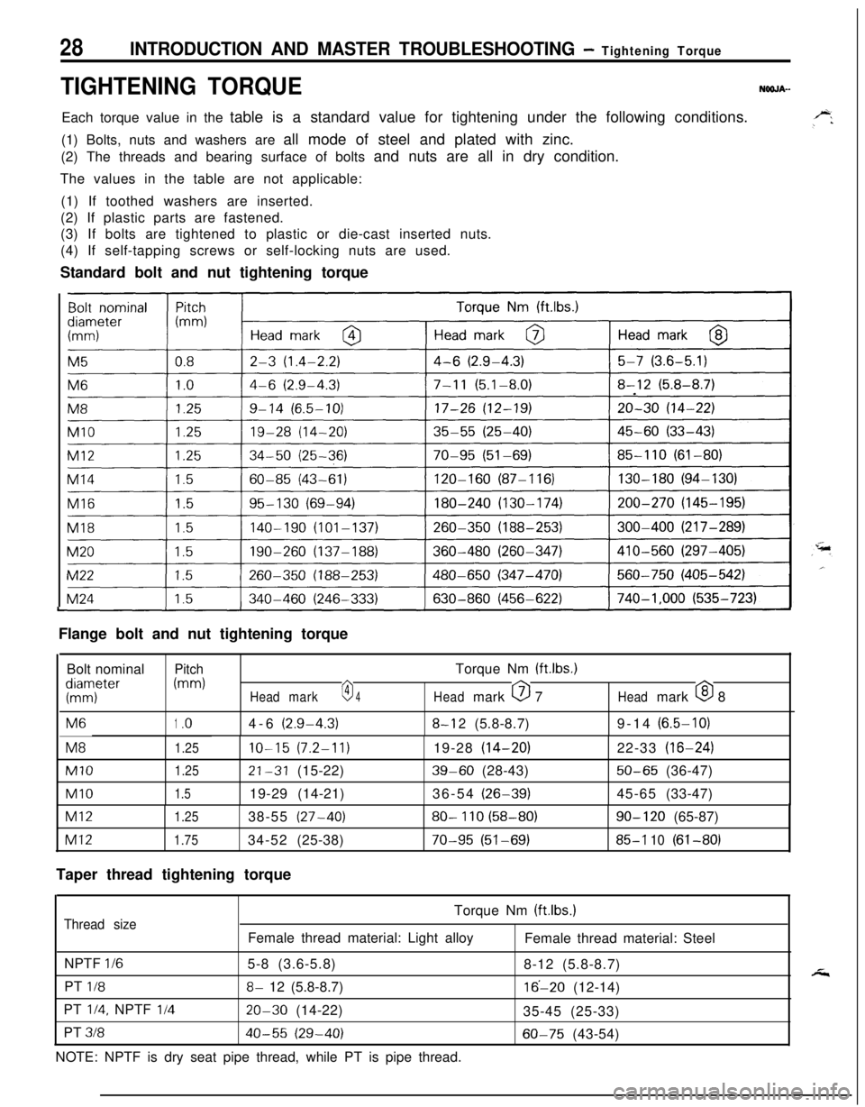
28INTRODUCTION AND MASTER TROUBLESHOOTING - Tightening Torque
TIGHTENING TORQUENOOJA-Each torque value in the table is a standard value for tightening under the following conditions.
(1) Bolts, nuts and washers are all mode of steel and plated with zinc.
(2) The threads and bearing surface of bolts and nuts are all in dry condition.
The values in the table are not applicable:
(1) If toothed washers are inserted.
(2) If plastic parts are fastened.
(3) If bolts are tightened to plastic or die-cast inserted nuts.
(4) If self-tapping screws or self-locking nuts are used.
Standard bolt and nut tightening torque
I
I
ILFlange bolt and nut tightening torque
Bolt nominal
PitchTorque Nm (ftlbs.)
KTter
(mm)
Headmark0 4Headmark 0 7Headmark 0 8M6
1.o4-6(2.9-4.3)8-l 2(5.8-8.7)9-14(6.5-10)M8
1.25IO-15(7.2-11)19-28(14-20)22-33(16-24)
Ml01.2521-31(15-22)39-60(28-43)50-65(36-47)
Ml01.519-29(14-21)36-54(26-39)45-65(33-47)
Ml21.2538-55(27-40)80- 110 (58-80)90- 120(65-87)
Ml21.7534-52(25-38)70-95 (51-69)85-l 10(61-80)
Taper thread tightening torque
Torque Nm (ftlbs.)
Thread sizeFemale thread material: Light alloy
Female thread material: Steel
NPTF
l/65-8 (3.6-5.8)
8-12 (5.8-8.7)
PT
l/88- 12 (5.8-8.7)16’-20 (12-14)
PT
l/4, NPTF I/420-30 (14-22)
35-45 (25-33)
PT
31840-55 (29-40)60-75 (43-54)
NOTE: NPTF is dry seat pipe thread, while PT is pipe thread.
Page 29 of 1216
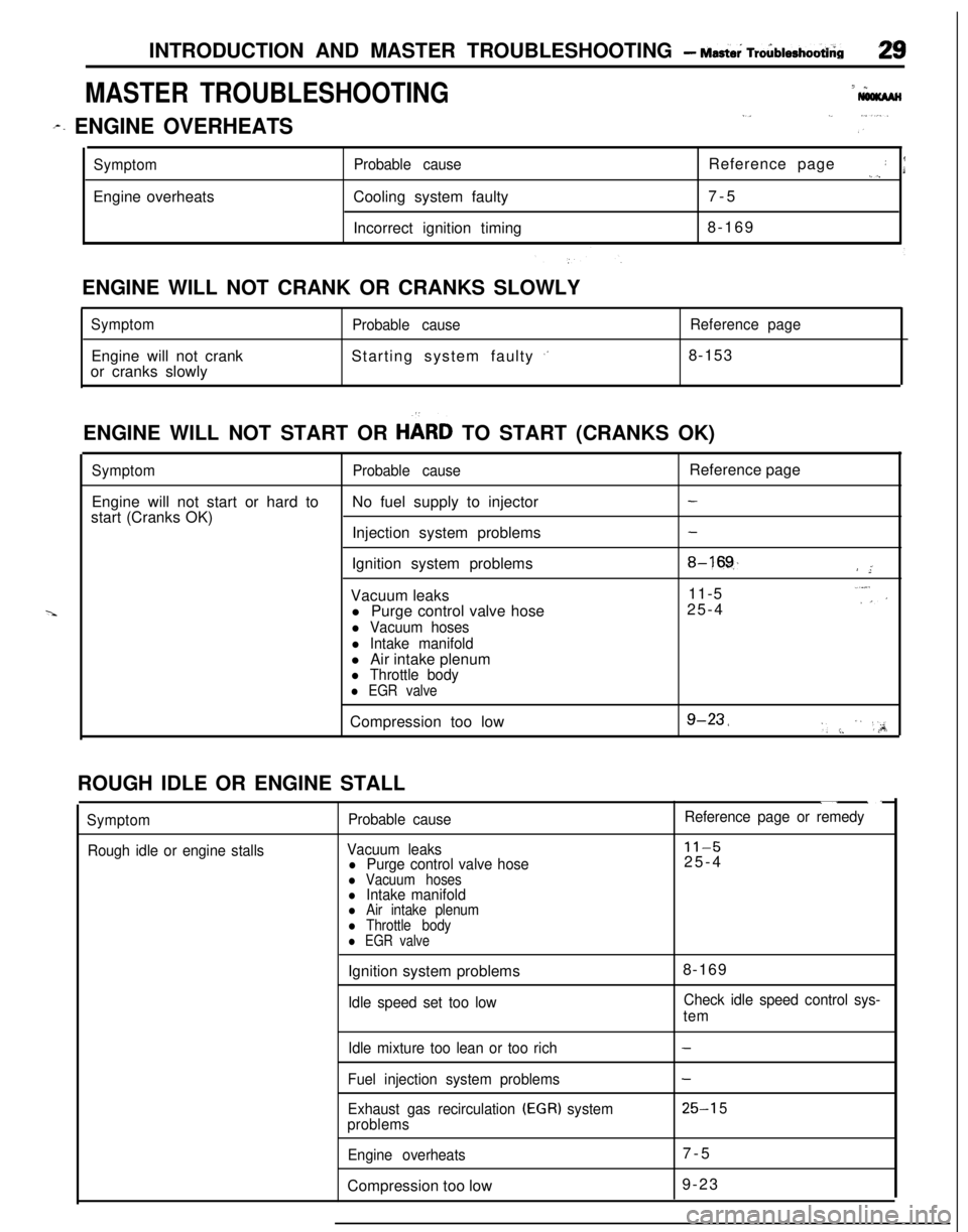
INTRODUCTION AND MASTER TROUBLESHOOTING - Mast& Tro6blerhootbia
MASTER TROUBLESHOOTING7 *
I,._ ,...
r. ENGINE OVERHEATSi ”
SymptomEngine overheatsProbable causeCooling system faulty
Incorrect ignition timingReference page: I._),7-5
8-169
ENGINE WILL NOT CRANK OR CRANKS SLOWLY
SymptomEngine will not crank
or cranks slowlyProbable causeStarting system faulty
,’
Reference page8-153
ENGINE WILL NOT START OR
HbRD TO START (CRANKS OK)
SymptomProbable causeReference page
Engine will not start or hard toNo fuel supply to injector
-start (Cranks OK)
Injection system problems
-Ignition system problems
8-16!$/ ”;Vacuum leaks11-5..“,:’l Purge control valve hose25-4
l Vacuum hoses
l Intake manifoldl Air intake plenum
l Throttle body
l EGR valveCompression too low
g-23,‘, :. ” ‘,;A;ROUGH IDLE OR ENGINE STALL
Symptom
Rough idle or engine stallsProbable cause
Vacuum leaks
l Purge control valve hosel Vacuum hosesl Intake manifoldl Air intake plenuml Throttle bodyl EGR valve
“. ._
Reference page or remedy
11-525-4
Ignition system problems
Idle speed set too low8-169Check idle speed control sys-
tem
Idle mixture too lean or too rich
Fuel injection system problems
Exhaust gas recirculation
(EGR) system
problems
Engine overheatsCompression too low
-
-
25-l 57-5
9-23
Page 30 of 1216
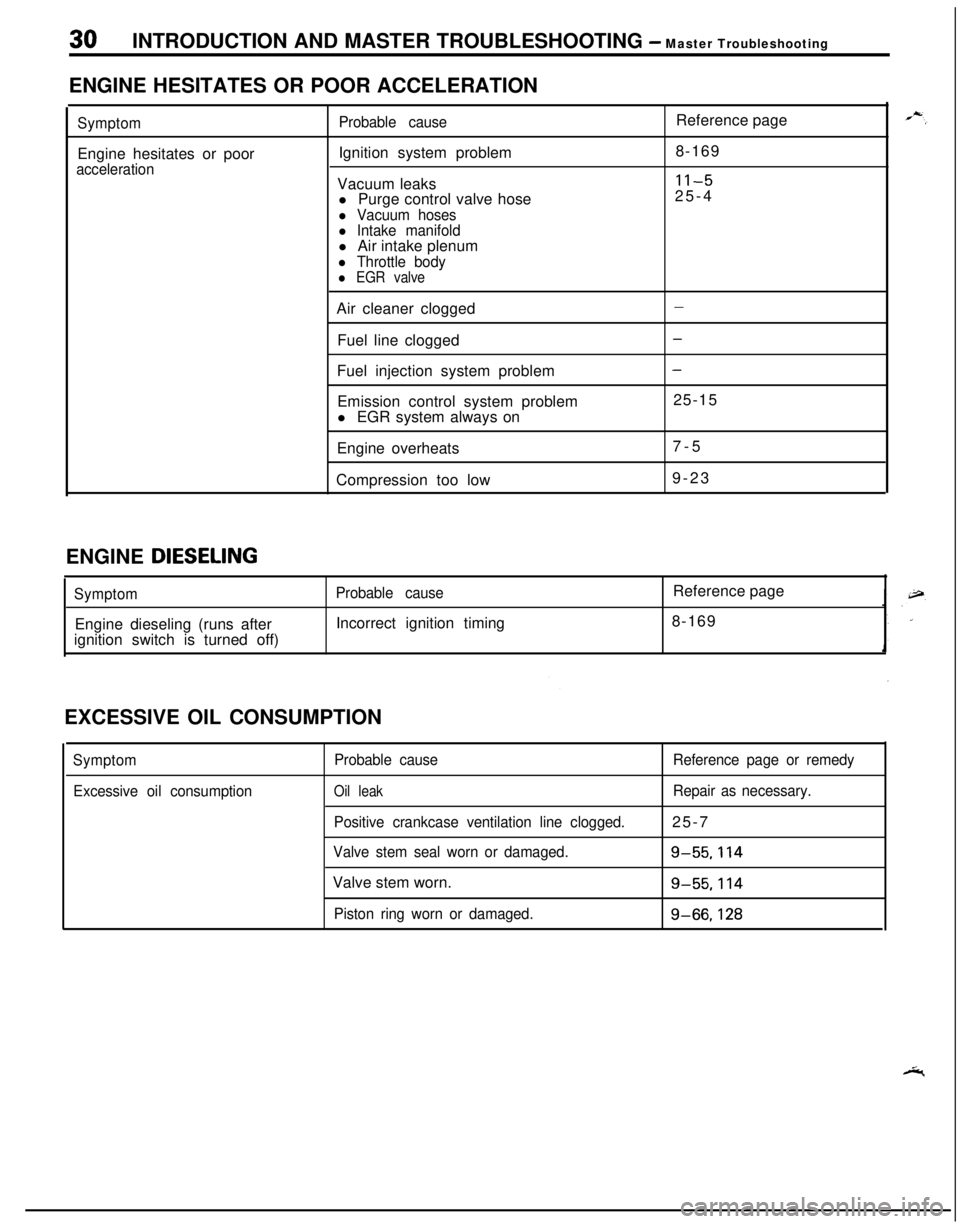
30INTRODUCTION AND MASTER TROUBLESHOOTING - Master Troubleshooting
ENGINE HESITATES OR POOR ACCELERATION
SymptomEngine hesitates or poor
accelerationProbable causeIgnition system problem
Vacuum leaks
l Purge control valve hose
l Vacuum hosesl Intake manifoldl Air intake plenum
l Throttle bodyl EGR valveReference page
8-169
11-525-4
Air cleaner clogged
Fuel line clogged
Fuel injection system problem
Emission control system problem
l EGR system always on
Engine overheats
Compression too low
-
-
-25-15
7-5
9-23
ENGINE
DIESELING
SymptomEngine dieseling (runs after
ignition switch is turned off)Probable causeIncorrect ignition timingReference page
8-169
EXCESSIVE OIL CONSUMPTION
Symptom
Excessive oil consumptionProbable cause
Oil leak
Positive crankcase ventilation line clogged.
Valve stem seal worn or damaged.Valve stem worn.
Piston ring worn or damaged.Reference page or remedy
Repair as necessary.25-7
g-55.114
g-55.114
g-66,128