lock MITSUBISHI ECLIPSE 1991 Service Manual
[x] Cancel search | Manufacturer: MITSUBISHI, Model Year: 1991, Model line: ECLIPSE, Model: MITSUBISHI ECLIPSE 1991Pages: 1216, PDF Size: 67.42 MB
Page 638 of 1216
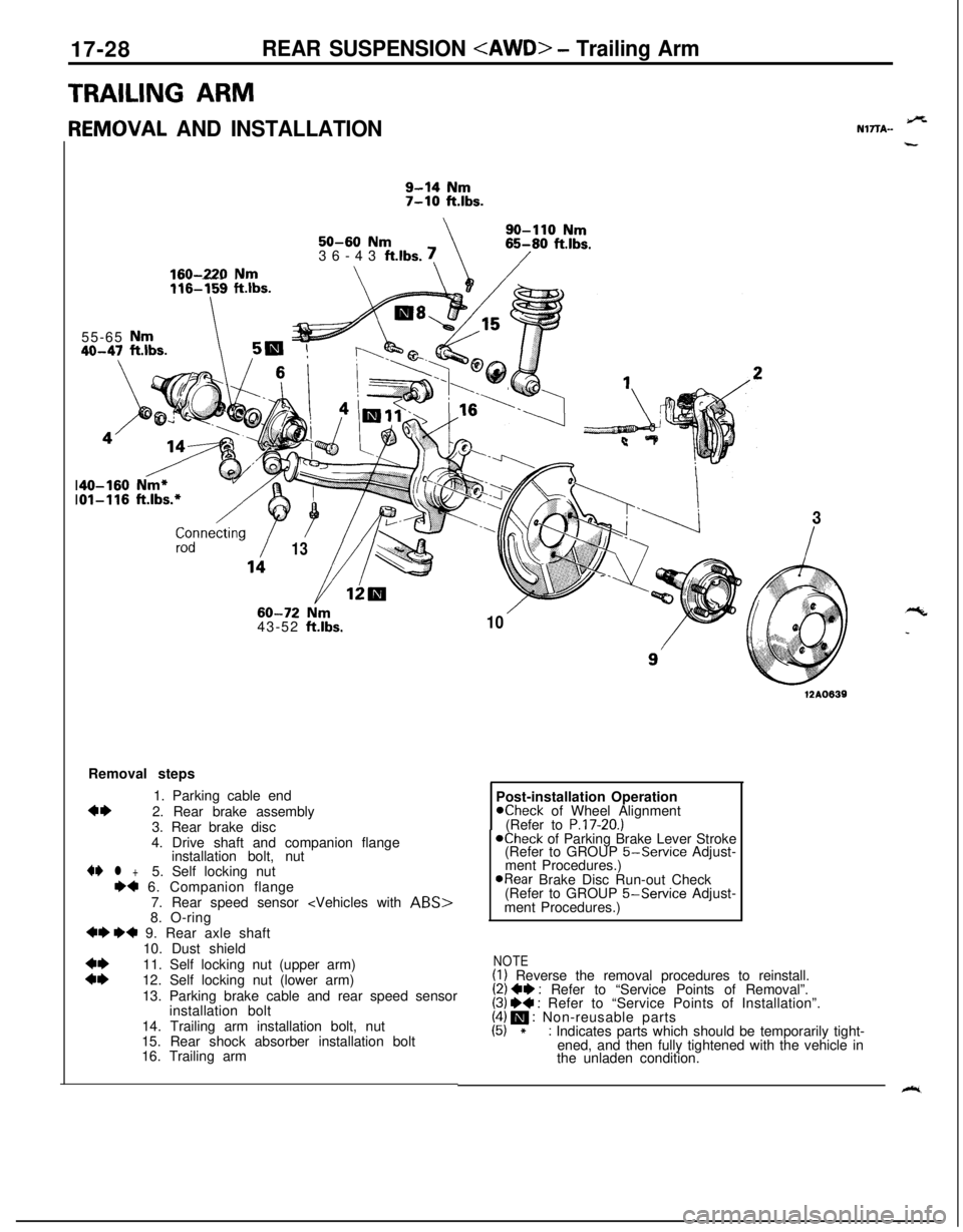
17-28REAR SUSPENSION
TRAILING ARMr
{EMOVAL AND INSTALLATION
9-14 Nm7-10 ft.lbs.
\SO-110
Nm50-60 Nm36-43 ft.lbs. !65-80 ftlbs.
/160-220 Nm\\\ /zdnnecting
/
/
13
_-_ --- .~~~~116-159 ftlbs.55-65
Nm40-47 ft.lbs.5m
60-72 Nrn43-52 ft.lbs.
/-\
103Removal steps
1. Parking cable end
4*2. Rear brake assembly
3. Rear brake disc
4. Drive shaft and companion flange
installation bolt, nut4I)
l +5. Self locking nut++ 6. Companion flange
7. Rear speed sensor
+I) ++ 9. Rear axle shaft
10. Dust shield
::11. Self locking nut (upper arm)
12. Self locking nut (lower arm)
13. Parking brake cable and rear speed sensor
installation bolt
14. Trailing arm installation bolt, nut
15. Rear shock absorber installation bolt
16. Trailing arm
12A0639Post-installation Operation
Kheck of Wheel Alignment
(Refer to P.17-20.)@Check of Parking Brake Lever Stroke
(Refer to GROUP 5-Service Adjust-
ment Procedures.)
@Rear Brake Disc Run-out Check
(Refer to GROUP 5-Service Adjust-
ment Procedures.)
NOTE(I) Reverse the removal procedures to reinstall.(2) ++ : Refer to “Service Points of Removal”.(3) W : Refer to “Service Points of Installation”.(4) m : Non-reusable parts(5) *: Indicates parts which should be temporarily tight-
ened, and then fully tightened with the vehicle in
the unladen condition.
9%NlTTA-
“c
_
k.
Page 639 of 1216
REAR SUSPENSION
12A008’I
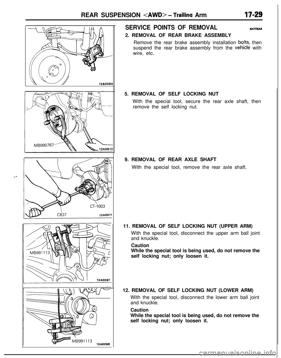
SERVICE POINTS OF REMOVALu17mAA2. REMOVAL OF REAR BRAKE ASSEMBLY
Remove the rear brake assembly installation
bolts, then
suspend the rear brake assembly from the
vehrcle, with
wire, etc.
5. REMOVAL OF SELF LOCKING NUT
With the special tool, secure the rear axle shaft, then
remove the self locking nut.
9. REMOVAL OF REAR AXLE SHAFT
With the special tool, remove the rear axle shaft.
11. REMOVAL OF SELF LOCKING NUT (UPPER ARM)
With the special tool, disconnect the upper arm ball joint
and knuckle.
Caution
While the special tool is being used, do not remove the
self locking nut; only loosen it.
12. REMOVAL OF SELF LOCKING NUT (LOWER ARM)
With the special tool, disconnect the lower arm ball joint
and knuckle.
Caution
While the special tool is being used, do not remove the
self locking nut; only loosen it.
Page 641 of 1216
REAR SUSPENSION
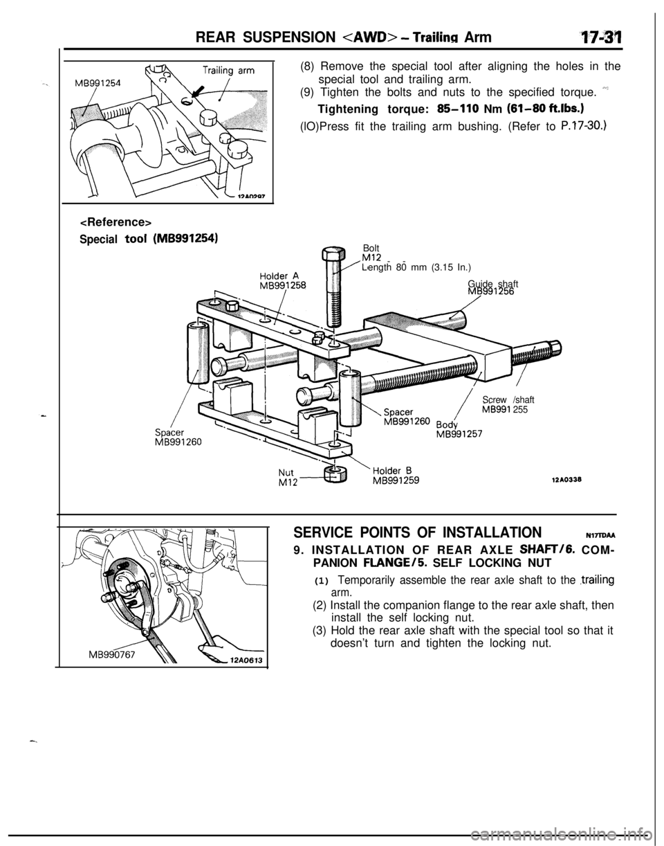
Specialtool(MB9912541(8) Remove the special tool after aligning the holes in the
special tool and trailing arm.
(9) Tighten the bolts and nuts to the specified torque.
“’Tightening torque:
85-110 Nm (81-80 ft.lbs.)(lO)Press fit the trailing arm bushing. (Refer to
P.?7-30.)Bolt
Ml2LI--
ength 80 mm (3.15 In.)
Guide shaft
/Screw /shaft
/MB591 255
12AO338
SERVICE POINTS OF INSTALLATION
NlTlDAA9. INSTALLATION OF REAR AXLE SHAFT/G. COM-
PANION
FLANGE/5. SELF LOCKING NUT
(1) Temporarily assemble the rear axle shaft to the ,trailing
arm.(2) Install the companion flange to the rear axle shaft, then
install the self locking nut.
(3) Hold the rear axle shaft with the special tool so that it
doesn’t turn and tighten the locking nut.
Page 645 of 1216
-.
J-
REAR SUSPENSION
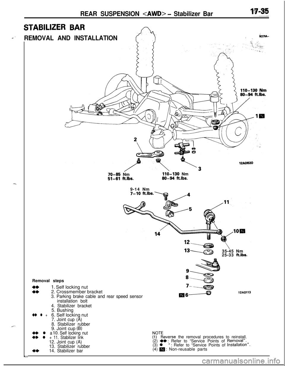
STABILIZER BAR:_-REMOVAL AND INSTALLATION/rq7lA-i.i;: 112AO620
70-85 Nm110-130 Nm51-81 ft.lbs.80-94 ftlbs.9-14 Nm
7-10 ft.lbs./4
IL-v \
‘3w35-45 Nm
25-33 ft.lbg.Removal steps
::
1. Self locking nut
2. Crossmember bracket‘----e212A01133. Parking brake cable and rear speed sensormeA
installation bolt
4. Stabilizer bracket5. Bushing
+e l +6. Self locking nut7. Joint cup (A)
8. Stabilizer rubber9. Joint cup
(B)+e l a 10. Self locking nut++ l + 11. Stabilizer link!ykeverse the removal procedures to reinstall.
12. Joint cup (A)(2) +I) : Refer to “Service Points of Removyl”.
13. Stabilizer rubber(3) l * : Refer to “Service Points of Installation”.
4*14. Stabilizer bar(4) m : Non-reusable parts
L
Page 646 of 1216
17-36REAR SUSPENSION
/12AOllO
\.1210111
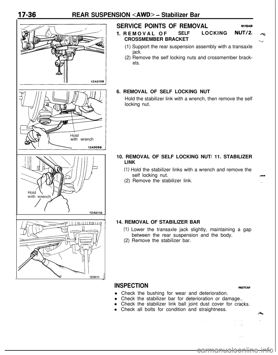
SERVICE POINTS OF REMOVALNl7ljMB
1. REMOVAL OFSELFLOCKINGNUT/P.CROSSMEMBER BRACKET
(1) Support the rear suspension assembly with a transaxle
jack.(2) Remove the self locking nuts and crossmember brack-
ets.6. REMOVAL OF SELF LOCKING NUT
Hold the stabilizer link with a wrench, then remove the self
locking nut.
10. REMOVAL OF SELF LOCKING NUT/ 11. STABILIZER
LINK
(1) Hold the stabilizer links with a wrench and remove the
self locking nut.
(2) Remove the stabilizer link.
14. REMOVAL OF STABILIZER BAR
(1) Lower the transaxle jack slightly, maintaining a gap
between the rear suspension and the body.
(2) Remove the stabilizer bar.7
INSPECTIONNOZTCAFl Check the bushing for wear and deterioration.
l Check the stabilizer bar for deterioration or damage..
l Check the stabilizer link ball joint dust cover for
cracks.l Check all bolts for condition and straightness.
Page 647 of 1216
-.REAR SUSPENSION
- Stabilizer Bar17-37Clip
ring
12LO217
Jrpose
\12LQ243
Hold with
wrench
12AOlOO
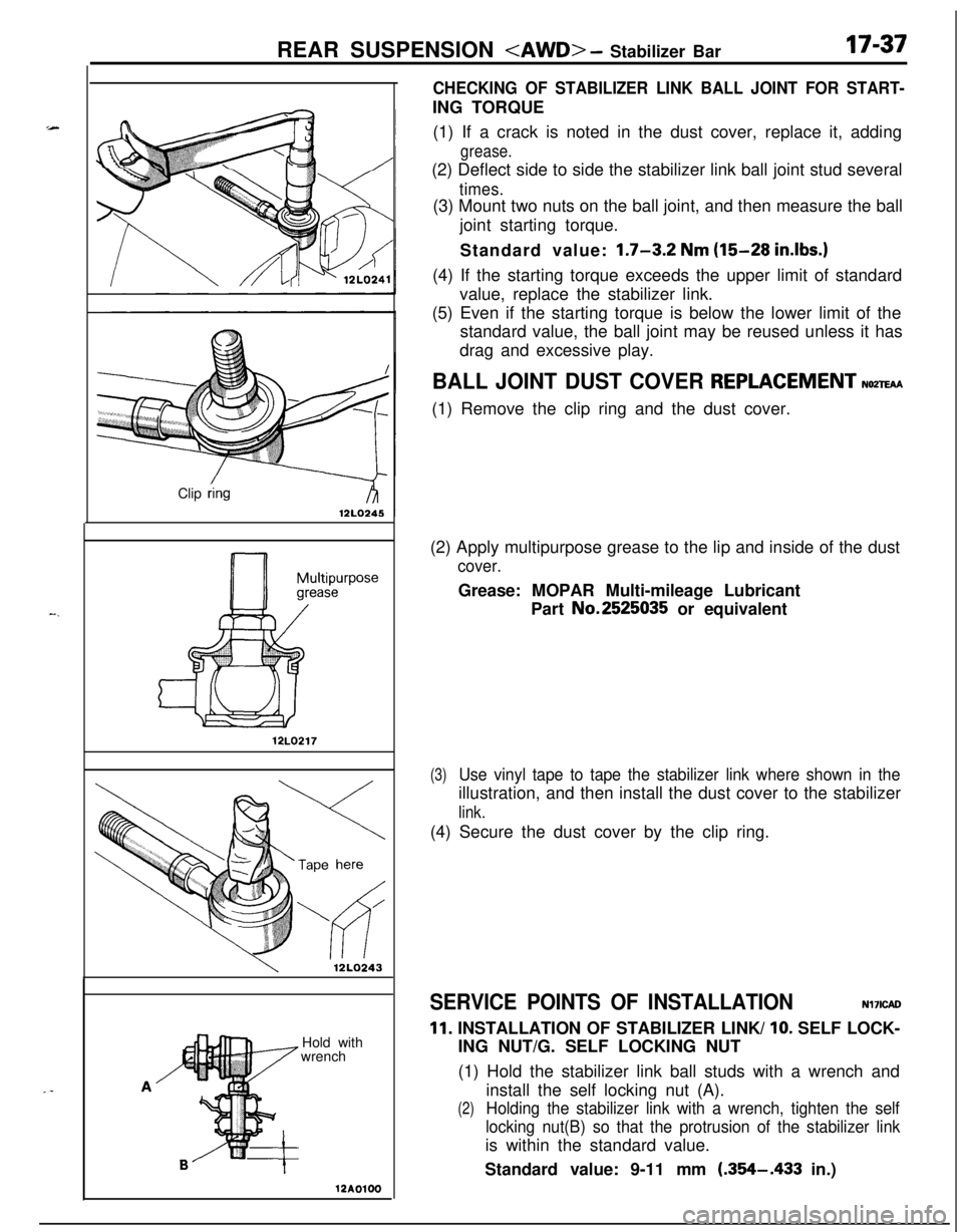
CHECKING OF STABILIZER LINK BALL JOINT FOR START-ING TORQUE
(1) If a crack is noted in the dust cover, replace it, adding
grease.(2) Deflect side to side the stabilizer link ball joint stud several
times.(3) Mount two nuts on the ball joint, and then measure the ball
joint starting torque.
Standard value:
1.7-3.2 Nm (15-28 in.lbs.)(4) If the starting torque exceeds the upper limit of standard
value, replace the stabilizer link.
(5) Even if the starting torque is below the lower limit of the
standard value, the ball joint may be reused unless it has
drag and excessive play.
BALL JOINT DUST COVER REPLACEMENTNozm(1) Remove the clip ring and the dust cover.
(2) Apply multipurpose grease to the lip and inside of the dust
cover.Grease: MOPAR Multi-mileage Lubricant
Part No.2525035 or equivalent
(3)Use vinyl tape to tape the stabilizer link where shown in theillustration, and then install the dust cover to the stabilizer
link.(4) Secure the dust cover by the clip ring.
SERVICE POINTS OF INSTALLATIONNl7ICAO
11. INSTALLATION OF STABILIZER LINK/ 10. SELF LOCK-
ING NUT/G. SELF LOCKING NUT
(1) Hold the stabilizer link ball studs with a wrench and
install the self locking nut (A).
(2)Holding the stabilizer link with a wrench, tighten the self
locking nut(B) so that the protrusion of the stabilizer linkis within the standard value.
Standard value: 9-11 mm
(.354-.433 in.)
Page 651 of 1216
-
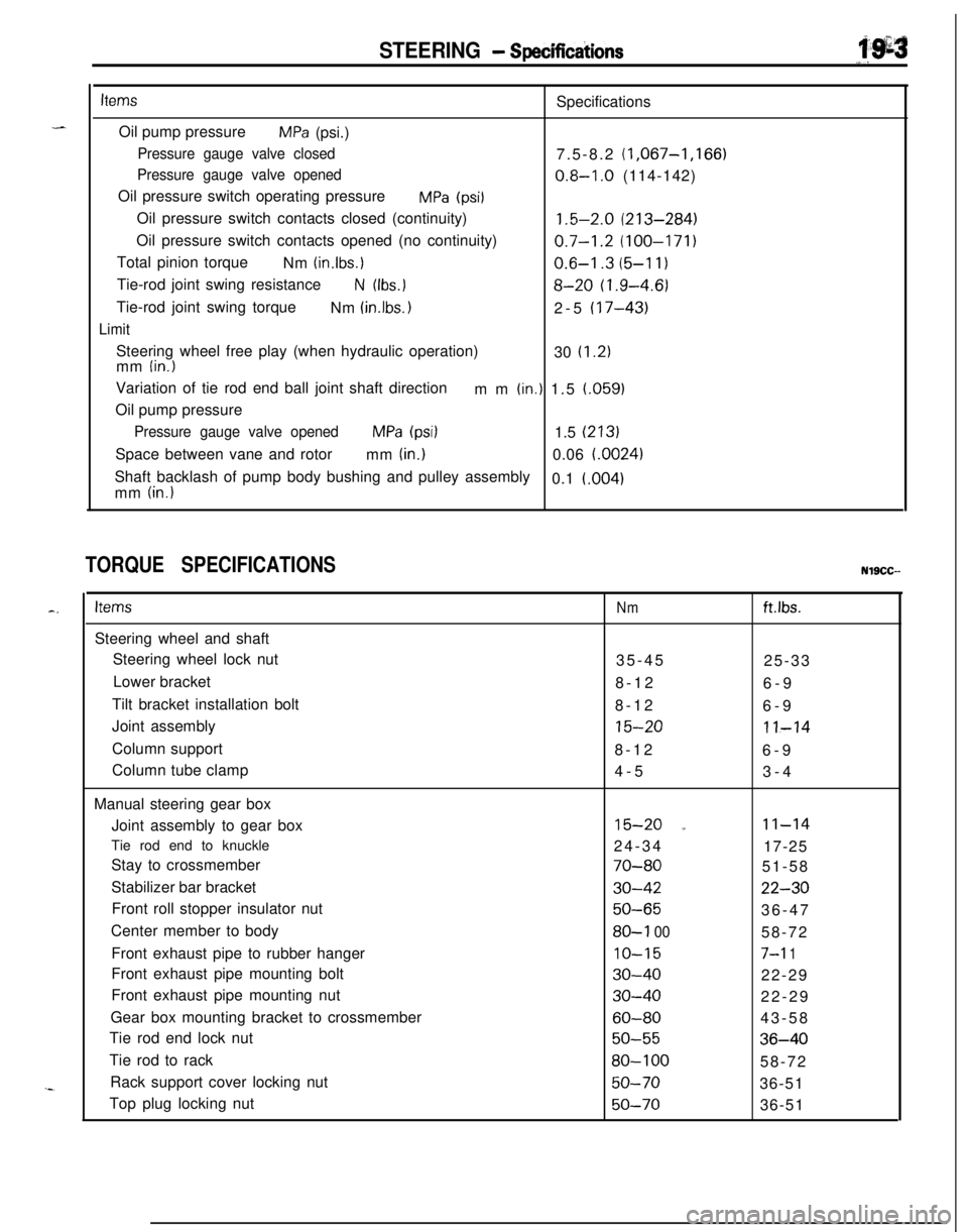
STEERING - Specificdions
i’.g=s
“,.
itemsSpecifications
Oil pump pressure
MPa (psi.)
Pressure gauge valve closed7.5-8.2 (1,067-1,166)
Pressure gauge valve opened0.8-I .O (114-142)
Oil pressure switch operating pressure
MPa (psi1Oil pressure switch contacts closed (continuity)
1.5-2.0 (213-284)Oil pressure switch contacts opened (no continuity)
0.7-1.2 (100-171)Total pinion torque
Nm
(in.lbs.)0.6-I .3 (5-l 1)Tie-rod joint swing resistance
N (Ibs.18-20 (1.9-4.6)Tie-rod joint swing torque
Nm
(in.lbs. 12-5 (17-43)
LimitSteering wheel free play (when hydraulic operation)
30
(1.2)mm (in.)Variation of tie rod end ball joint shaft direction
mm
(in.) 1.5 (.059)
Oil pump pressure
Pressure gauge valve openedMPa (psi)1.5 (213)Space between vane and rotor
mm
(in.)0.06 i.0024)Shaft backlash of pump body bushing and pulley assembly
0.1
i.004)mm (in.)
TORQUE SPECIFICATIONSNlSCC--
c.ItemsSteering wheel and shaft
Steering wheel lock nut
Lower bracket
Tilt bracket installation bolt
Joint assembly
Column support
Column tube clamp
Manual steering gear box
Joint assembly to gear box
Tie rod end to knuckle
Stay to crossmember
Stabilizer bar bracket
Front roll stopper insulator nut
Center member to body
Front exhaust pipe to rubber hanger
Front exhaust pipe mounting bolt
Front exhaust pipe mounting nut
Gear box mounting bracket to crossmember
Tie rod end lock nut
Tie rod to rack
Rack support cover locking nut
Top plug locking nutNmftlbs.35-45
25-33
8-12
6-9
8-12
6-9
15-2011-148-12
6-9
4-5
3-4
15-20 a11-1424-34
17-25
70-8051-58
30-4222-30
50-6536-47
80-l 0058-72
IO-157-l 1
30-4022-29
30-4022-29
60-8043-58
50-5536-40
80-10058-72
50-7036-51
50-7036-51
Page 652 of 1216
19-4STEERING - Specifications
ItemsNmIft.lbs.Power steering gear box
Joint assembly
Pressure hose to gear box
Return tube to gear box
Tie rod end to knuckle
Stay to crossmember
Stabilizer bar bracket
Front roll stopper insulator nut
Centermember to body
Front exhaust pipe to rubber hanger
Front exhaust pipe mounting bolt
Front exhaust pipe mounting nut
Tie rod end lock nut
Tie rod to rack
Feed tubes
End plugPinion and valve assembly to self-locking nut
Rack support cover locking nut
Valve housing installation bolts
Power steering oil pump
Pressure hose to oil pump
Oil pump to oil pump bracket
Heat protector installation nut
Oil pump bracket to engine
1.8L Engine
Front side
Left side2.0L DOHC Engine
Oil reservoir installation bolt
Oil reservoir bracket installation bolt
Pump cover to pump body
Suction connector to pump body
Connector to pump body
Terminal assembly to pump body
ower steering hoses
Cooler tube to body
Cooler tube to hood lock stay
Cooler tube clamp
Return tube to body
Pressure tube to gear box
Return tube to gear box
Pressure hose to body
Pressure hose to oil pump
Pressure hose to pressure tube
Pressure hose bracket11-14
9-13
9-13
17-25
51-58
22-3036-47
58-72
7-11
22-29
22-29
43-58
36-4058-72
9-13
36-51
14-22
36-51
12-19
15-2012-18
12-18
24-34
70-80
30-42
50-65
80-100
10-15
30-40
30-40
60-80
50-55
80-10012-18
50-70
20-30
50-7017-26
14-21
10-1535-45
25-33
9-14
7-1027-41
20-3025-33
18-24
25-33
18-24
9-14
7-109-14
7-1018-22
13-16
6-104-7
50-7036-51
25-3018-22
9-14
7-104-6
29-43
3.0-4.5'2-3
9-14
7-1012-18
9-13
12-18
9-13
9-14
7-1014-21
IO-15
30-4022-29
9-14
7-10
Page 657 of 1216
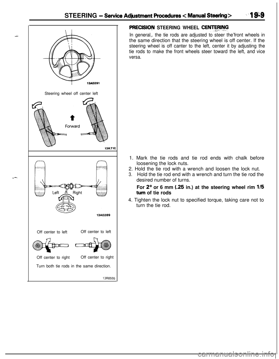
STEERING - Service Adjustment Procedures < Manual Steering>_ i ‘I 9;sSteering wheel off center left
13K71013A0289
Off center to leftOff center to left
Off center to rightOff center to right
Turn both tie rods in the same direction.
PRECISIG~ STEERING WHEEL CENTFFJIhll
In general,. the tie rods are adjusted to steer the’front wheels inthe same direction that the steering wheel is off center. If the
steering wheel is off canter to the left, center it by adjusting the
tie rods to make the front wheels steer toward the left, and vice
versa.1. Mark the tie rods and tie rod ends with chalk before
loosening the lock nuts.
2. Hold the tie rod with a wrench and loosen the lock nut.
3.Hold the tie rod end with a wrench and turn the tie rod the
desired number of turns.
For
2O or 6 mm (.25 in.) at the steering wheel rim 115
turn of tie rods
4. Tighten the lock nut to specified torque, taking care not to
turn the tie rod.
Page 664 of 1216
19-16STEERING - Steering Wheel and Shaft
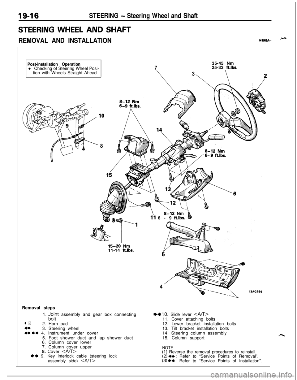
STEERING WHEEL AND SHAFT
REMOVAL AND INSTALLATIONNlL)GA- ‘-
Post-installation Operationl Checking of Steering Wheel Posi-
tion with Wheels Straight Ahead
835-45 Nm
725-33 ft.lbs.
\
3
\\
15-20 Nm
11-14 ft.lbs.Removal steps
1.
“,c$t assembly and gear box connecting
l *2. Horn pad
4*3. Steering wheel
+* ++ 4. Instrument under cover
5. Foot shower duct and lap shower duct
6. Column cover lower
7. Column cover upper
8. Cover
assembly side)
\8-i2 Nm’11 6-9 ft.lbs.0
413AO296
+4 10. Slide lever 11. Cover attaching bolts
12. Lower bracket installation bolts
13. Tilt bracket installation bolts
14. Steering column assembly
15. Column support
NOTE(I) Reverse the removal procedures to reinstall.(2) a* : Refer to “Service Points of Removal”.(3) +a : Refer to “Service Points of Installation”.