lock MITSUBISHI ECLIPSE 1991 Service Manual
[x] Cancel search | Manufacturer: MITSUBISHI, Model Year: 1991, Model line: ECLIPSE, Model: MITSUBISHI ECLIPSE 1991Pages: 1216, PDF Size: 67.42 MB
Page 452 of 1216
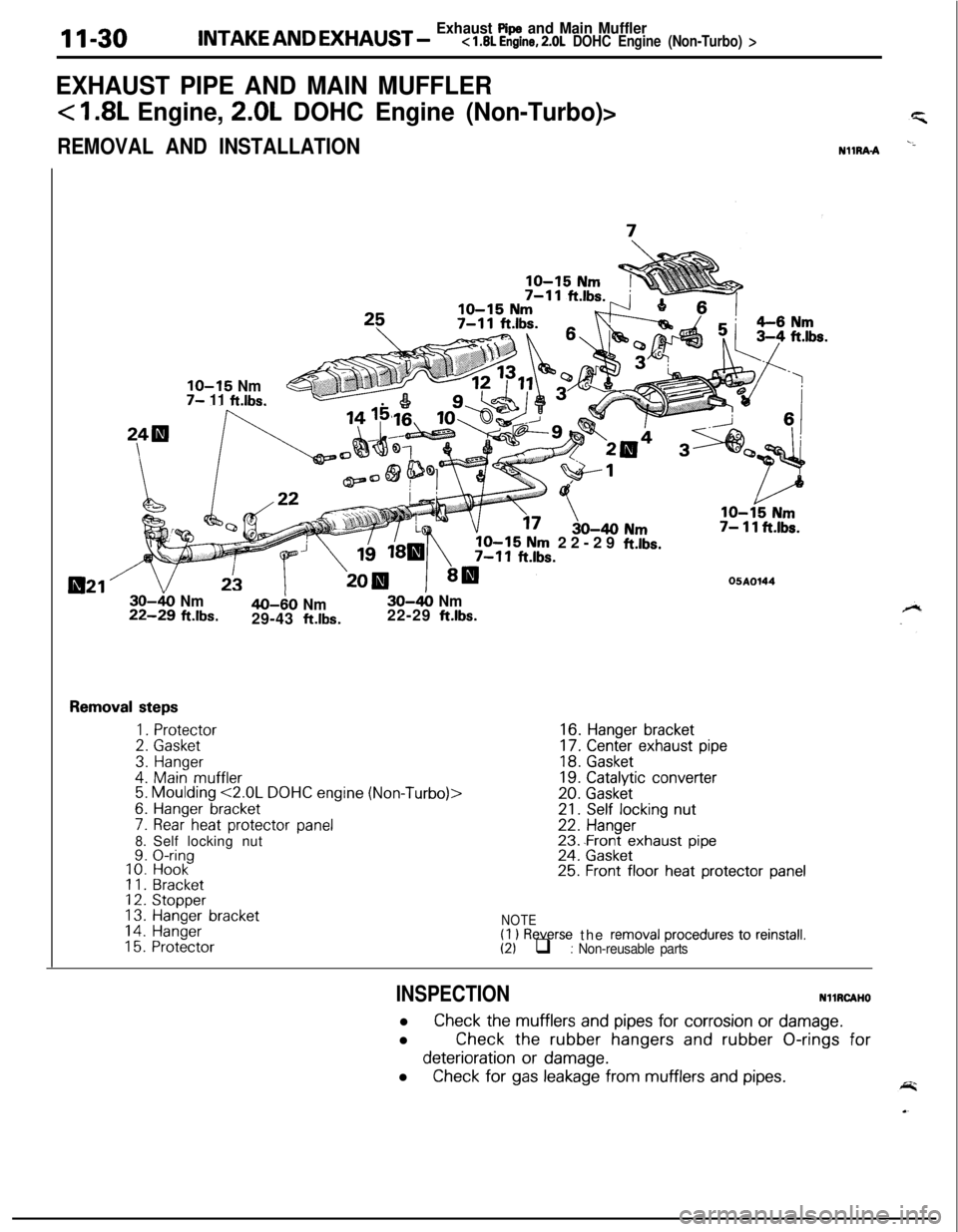
lNTAKE AND EXHAUST _ Exhaust Pspe and Main Mufflerc 1.8L Engine, 2.0L DOHC Engine (Non-Turbo) >
EXHAUST PIPE AND MAIN MUFFLER
< I .8L Engine, 2.0L DOHC Engine (Non-Turbo)>
REMOVAL AND INSTALLATIONN1lRA-A
021’
IO-15 Nm7- 11 ft.lbs.
IO-15 Nm 22-29 ft.lbs.7- 11 ft.lbs.
OSAO144
30-k) Nm22-29 ft.lbs.40-60 Nm29-43 ft.lbs.30-&o
Nm22-29 ft.lbs.
Removal steps
1.Protector
2.Gasket
3.Hanger
4.Main muffler5. Moulding <2.0L DOHC engine (Non-Turbo)>
6.Hanger bracket
7. Rear heat protector panel8.Self locking nut9.O-ringIO. Hook11. Bracket12.Stopper
13.Hanger bracket14.Hanger15. Protector
16.Hanger bracket
17.Center exhaust pipe
18.Gasket
19.Catalytic converter
20. Gasket21. Self locking nut
22.Hanger23..Front exhaust pipe24.Gasket25. Front floor heat protector panel
NOTE(I 1 Reverse the removal procedures to reinstall.(2) q : Non-reusable parts
INSPECTIONNHRCAHOl Check
the mufflers and pipes for corrosion or damage.
l
Check the rubber hangers and rubber O-rings for
deterioration or damage.
l Check
for gas leakage from mufflers and pipes.
Page 454 of 1216
Removal steps
1.Protector
2.Gasket3.Hanger4.Main muffler5.Hanger bracket6. Rear heat protector panel
7. Self locking nut
8.O-ring
9.Hook10.Bracket11.Stopper12.Hanger bracket
13.Hanger14.Protector15.Hanger bracket
16. Center exhaust pipe17.Gasket18.Catalyticconverter19.Gasket20. Self locking nut21.Hanger22. Front exhaust pipe
23.Gasket24. Front floor heat protector panel
NOTE
t(1) Reverse the removal procedures to reinstall(21 q : Non-reusable parts
INSPECTIONNllRCAHl
l Check the mufflers
and pipes for corrosion or damage.0
Check the rubber hangers and rubber O-rings for
deterioration or damage.0
Check for gas leakage from mufflers and pipes.
Page 459 of 1216
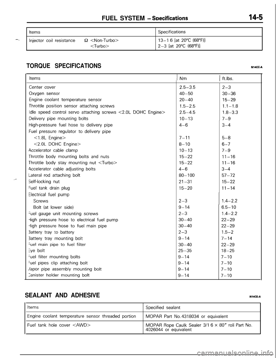
FUEL SYSTEM - SDecifications14-5
-.
Items
Injector coil resistance52
Specifications
13-I 6 [at 20°C (68”F)j
2-3 [at 20°C (68”F)I
TORQUE SPECIFICATIONSN14CC-A
,,-
ItemsINm1 ft.lbs.
Center cover
Oxygen sensor
Engine coolant temperature sensor
Throttle position sensor attaching screws
Idle speed control servo attaching screws <2.0L DOHC Engine>
Delivery pipe mounting bolts
High-pressure fuel hose to delivery pipe
Fuel pressure regulator to delivery pipe
<1.8L Engine>
<2.0L DOHC Engine>
Accelerator cable clamp
Throttle body mounting bolts and nuts
Throttle body stay mounting nut
4ccelerator cable adjusting bolts
Lateral rod attaching bolt
Self-locking nut
Fuel tank drain plug
Electrical fuel pump
Screws
Bolt (at lower side)Gel
gauge unit mounting screws
-ligh pressure hose to electrical fuel pump
iigh pressure hose to fuel main pipe
3attery tray to battery
3attery tray mounting boltGel
main pipe to fuel filter
Zye boltGel filter
mounting bolts
%el pipes clip attaching bolt
Japor pipe assembly mounting bolt
Ianister holder mounting bolt
2.5-3.5
40-50
20-40
1.5-2.5
2.5-4.5
IO-13
4-6
7-l 15-8
8-106-7
IO-137-9
15-2211-16
15-2211-16
4-63-4
80-l 0057-72
21-3115-22
15-2011-14
2-3
9-14
2-3
30-40
30-40
2-3
9-14
30-40
25-35
9-14
9-14
9-14
9-14
2-3
30-36
15-29
1.1-1.8
1.8-3.3
7-9
3-4
1.4-2.2
6.5-10
1.4-2.2
22-29
22-29
1.5-2
7-14
22-29
18-25
7-10
7-10
7-10
7-10
SEALANT AND ADHESIVENMCE-A
Items
Engine coolant temperature sensor threaded portion
Fuel tank hole cover
Specified sealant
MOPAR Part No.4318034 or equivalent
MOPAR Rope Caulk Sealer 3/l 6 x 80” roll Part No.4026044 or equivalent
Page 496 of 1216
14-42FUEL SYSTEM - Service Adjustment Procedures C1.8L Engine>
6FU13%
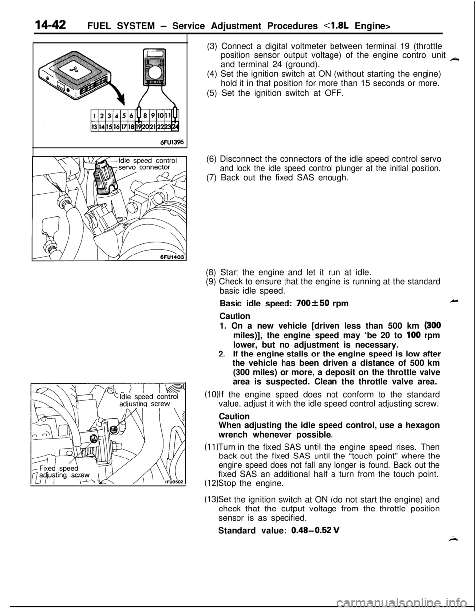
Idle speed control
adjusting screw(3) Connect a digital voltmeter between terminal 19 (throttle
position sensor output voltage) of the engine control unit
kand terminal 24 (ground).
(4) Set the ignition switch at ON (without starting the engine)
hold it in that position for more than 15 seconds or more.
(5) Set the ignition switch at OFF.
(6) Disconnect the connectors of the idle speed control servo
and lock the idle speed control plunger at the initial position.(7) Back out the fixed SAS enough.
(8) Start the engine and let it run at idle.
(9) Check to ensure that the engine is running at the standard
basic idle speed.
Basic idle speed:
700&50 rpm
CautionLr1. On a new vehicle [driven less than 500 km
(380miles)], the engine speed may ‘be 20 to
100 rpm
lower, but no adjustment is necessary.
2.If the engine stalls or the engine speed is low after
the vehicle has been driven a distance of 500 km
(300 miles) or more, a deposit on the throttle valve
area is suspected. Clean the throttle valve area.
(10)lf the engine speed does not conform to the standard
value, adjust it with the idle speed control adjusting screw.
Caution
When adjusting the idle speed control, use a hexagon
wrench whenever possible.
(11)Turn in the fixed SAS .until the engine speed rises. Then
back out the fixed SAS until the “touch point” where the
engine speed does not fall any longer is found. Back out thefixed SAS an additional half a turn from the touch point.
(12)Stop the engine.
(13)Set the ignition switch at ON (do not start the engine) and
check that the output voltage from the throttle position
sensor is as specified.
Standard value:
0.48-0.52 VA
Page 497 of 1216
FUEL SYSTEM - Service Adjustment Procedures <1.8L Engine>14-43
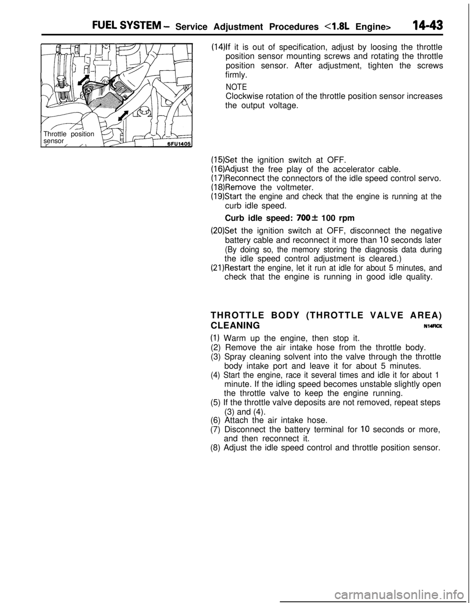
(14)lf it is out of specification, adjust by loosing the throttle
position sensor mounting screws and rotating the throttle
position sensor. After adjustment, tighten the screws
firmly.
NOTEClockwise rotation of the throttle position sensor increases
the output voltage.
Throttle position
sensor
t-/ /I
(15)Set the ignition switch at OFF.
(16)Adjust the free play of the accelerator cable.
(17)Reconnect the connectors of the idle speed control servo.
(18)Remove the voltmeter.
(19)Start the engine and check that the engine is running at thecurb idle speed.
Curb idle speed:
700f 100 rpm
(20)Set the ignition switch at OFF, disconnect the negative
battery cable and reconnect it more than
10 seconds later
(By doing so, the memory storing the diagnosis data duringthe idle speed control adjustment is cleared.)
(21)Restart the engine, let it run at idle for about 5 minutes, andcheck that the engine is running in good idle quality.
THROTTLE BODY (THROTTLE VALVE AREA)
CLEANING
NllRCK
(1) Warm up the engine, then stop it.
(2) Remove the air intake hose from the throttle body.
(3) Spray cleaning solvent into the valve through the throttle
body intake port and leave it for about 5 minutes.
(4) Start the engine, race it several times and idle it for about 1minute. If the idling speed becomes unstable slightly open
the throttle valve to keep the engine running.
(5) If the throttle valve deposits are not removed, repeat steps
(3) and (4).
(6) Attach the air intake hose.
(7) Disconnect the battery terminal for
10 seconds or more,
and then reconnect it.
(8) Adjust the idle speed control and throttle position sensor.
Page 504 of 1216
14-50FUEL SYSTEM - Service Adjustment Procedures <2.0L Engine>THROllLE
POSITION SENSOR ADJUSTME!-T’“.
(1) Slacken the accelerator cable enough.
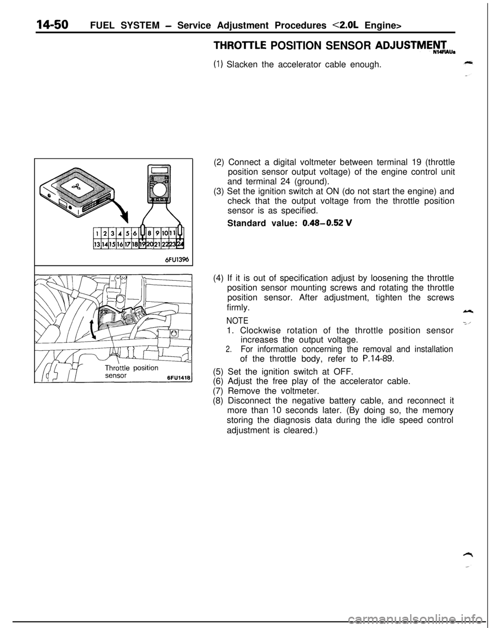
6FU13%(2) Connect a digital voltmeter between terminal 19 (throttle
position sensor output voltage) of the engine control unit
and terminal 24 (ground).
(3) Set the ignition switch at ON (do not start the engine) and
check that the output voltage from the throttle position
sensor is as specified.
Standard value:
0.48-0.52 V(4) If it is out of specification adjust by loosening the throttle
position sensor mounting screws and rotating the throttle
position sensor. After adjustment, tighten the screws
firmly.
NOTE1. Clockwise rotation of the throttle position sensor
increases the output voltage.
2.For information concerning the removal and installationof the throttle body, refer to
P.14-89.(5) Set the ignition switch at OFF.
(6) Adjust the free play of the accelerator cable.
(7) Remove the voltmeter.
(8) Disconnect the negative battery cable, and reconnect it
more than
10 seconds later. (By doing so, the memory
storing the diagnosis data during the idle speed control
adjustment is cleared.)
Page 506 of 1216
14-52FUEL SYSTEM - Service Adjustment Procedures <2.0L Engine>
IDLE POSITION SWITCH ADJUSTMENT
Caution
N14UDAThe idle position switch has been adjusted by the manu-
facturer.Do not, therefore, disturb the setting of the idle-position
switch.
If the setting is disturbed as a result of carelessness, or if
the idle-position switch is replaced, make the necessary
setting as described below.
(1) Sufficiently loosen the tension of the accelerator cable.
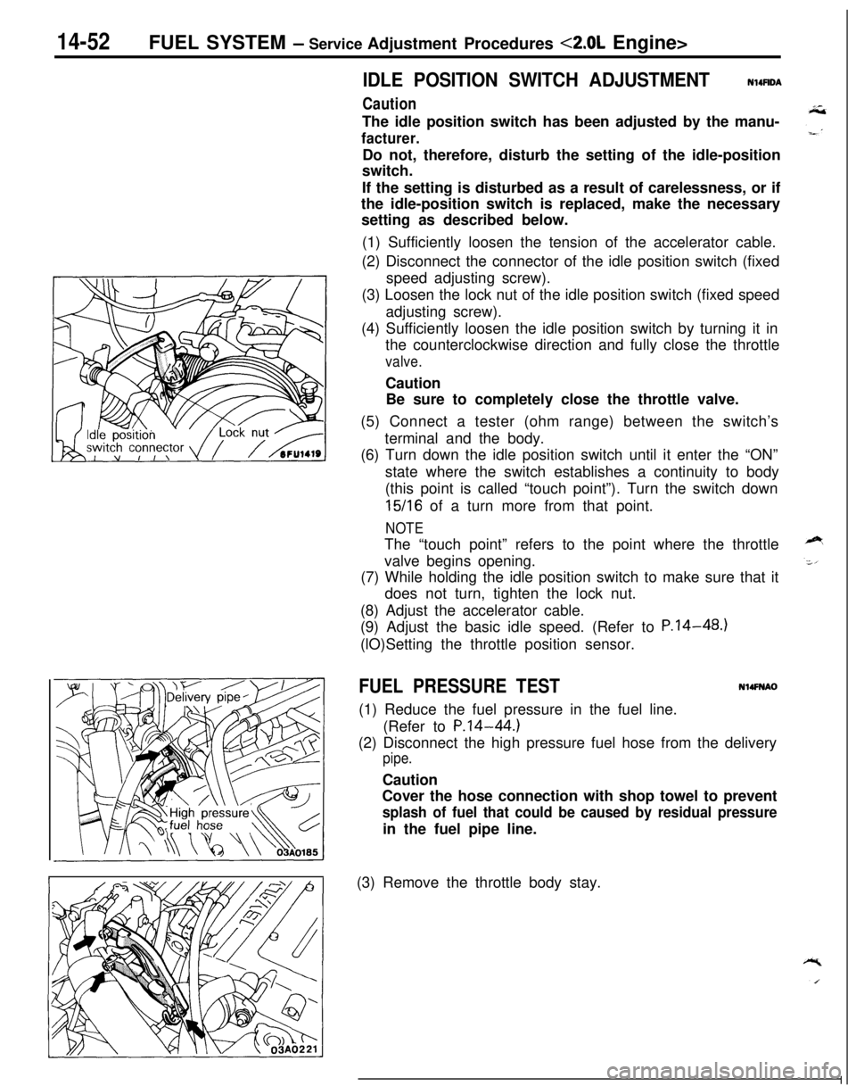
(2) Disconnect the connector of the idle position switch (fixed
speed adjusting screw).
(3) Loosen the lock nut of the idle position switch (fixed speed
adjusting screw).
(4) Sufficiently loosen the idle position switch by turning it in
the counterclockwise direction and fully close the throttle
valve.Caution
Be sure to completely close the throttle valve.
(5) Connect a tester (ohm range) between the switch’s
terminal and the body.
(6) Turn down the idle position switch until it enter the “ON”
state where the switch establishes a continuity to body
(this point is called “touch point”). Turn the switch down
15/16 of a turn more from that point.
NOTEThe “touch point” refers to the point where the throttle
valve begins opening.
(7) While holding the idle position switch to make sure that it
does not turn, tighten the lock nut.
(8) Adjust the accelerator cable.
(9) Adjust the basic idle speed. (Refer to P.14-48.)
(lO)Setting the throttle position sensor.
FUEL PRESSURE TESTN14FNAO(1) Reduce the fuel pressure in the fuel line.
(Refer to
P.14-44.)(2) Disconnect the high pressure fuel hose from the delivery
pipe.Caution
Cover the hose connection with shop towel to prevent
splash of fuel that could be caused by residual pressurein the fuel pipe line.
(3) Remove the throttle body stay.
Page 518 of 1216
14-64FUEL SYSTEM -MPI System Inspection <1.8L Engine>
Idle speed controlservo connector
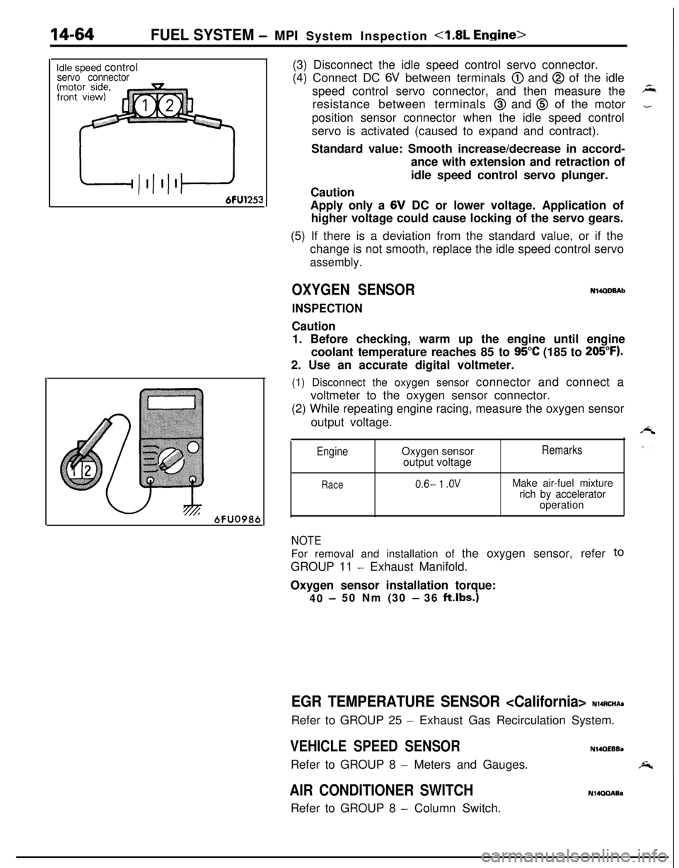
6FU098t(3) Disconnect the idle speed control servo connector.
(4) Connect DC
6V between terminals @) and @ of the idle
speed control servo connector, and then measure the
resistance between terminals
@ and @ of the motor
position sensor connector when the idle speed control
servo is activated (caused to expand and contract).
Standard value: Smooth increase/decrease in accord-
ance with extension and retraction of
idle speed control servo plunger.
Caution
Apply only a 6V DC or lower voltage. Application of
higher voltage could cause locking of the servo gears.
(5) If there is a deviation from the standard value, or if the
change is not smooth, replace the idle speed control servo
assembly.
OXYGEN SENSORN14QDBAb
INSPECTIONCaution
1. Before checking, warm up the engine until engine
coolant temperature reaches 85 to
95°C (185 to 205°F).2. Use an accurate digital voltmeter.
(1) Disconnect the oxygen sensor connector and connect a
voltmeter to the oxygen sensor connector.
(2) While repeating engine racing, measure the oxygen sensor
output voltage.
EngineOxygen sensor
output voltageRemarks
Race0.6- 1 .OVMake air-fuel mixture
rich by accelerator
operation
NOTEFor removal and installation of the oxygen sensor, refer
toGROUP 11
- Exhaust Manifold.
Oxygen sensor installation torque:
40
-50 Nm (30 - 36 klbs.)
EGR TEMPERATURE SENSOR
- Exhaust Gas Recirculation System.
VEHICLE SPEED SENSORN14QEEBaRefer to GROUP 8
- Meters and Gauges.
AIR CONDITIONER SWITCHRefer to GROUP 8
- Column Switch.
N14QQABa
Page 520 of 1216
14-66FUEL SYSTEM -MPI System Inspection 4.8L Engine>
6FU1253
-1 Batterv
I6FUO751
03AOO50
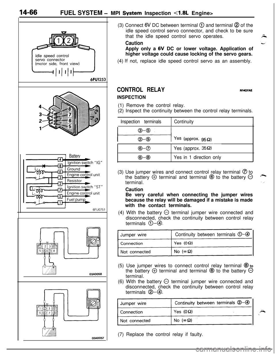
03AOO57(3) Connect
6V DC between terminal @ and terminal @ of the
idle speed control servo connector, and check to be sure
that the idle speed control servo operates.
CautionApply only a 6V DC or lower voltage. Application of
higher voltage could cause locking of the servo gears.
(4)
If not, replace idle speed control servo as an assembly.
CONTROL RELAY
INSPECTION
NWWAE(1) Remove the control relay.
(2) Inspect the continuity between the control relay terminals.
Inspection terminalsContinuity
l---$+-l Yes (approx. 9552)
B-0
@-@
~~~
Yes (approx. 35Q)
Yes in 1 direction only(3) Use jumper wires and connect control relay terminal
@ to
the battery
@ terminal and terminal @ to the battery @
terminal.Caution
Be very careful when connecting the jumper wires
because the relay will be damaged if a mistake is made
with the contact terminals.
(4) With the battery
0 terminal jumper wire connected and
disconnected, check the continuity between control relay
terminals @-@I.
Continuity between terminals 0-B(5) Use jumper wires to connect control relay terminal
@I to
the battery
@ terminal and terminal @ to the battery 0
terminal.(6) With the battery
0 terminal jumper wire connected and
disconnected, check the continuity between control relay
terminals @-@I.
Continuity between terminals 0-a
1(7) Replace the control relay if faulty.
Page 536 of 1216
14-82FUEL SYSTEM - MPI System Inspection <2.0L DOHC Engine>
\ \\I \3FUO352
,\ \
\I \3FUO353
,\ ‘\R/
\ \\I \3FUo354
POWER TRANSISTORRefer to GROUP 8
- Ignition System
NlIAcQAl
a-4
AIR CONDITIONER POWER RELAYN14NCl.a -Refer to GROUP 24
- Air Conditioner.
PURGE CONTROL SOLENOID VALVEN14RCKARefer to GROUP 25
- Evaporative Emission Control System.
EGR CONTROL SOLENOID VALVE
N14NCURefer to GROUP 25
- Exhaust Gas Recirculation System.
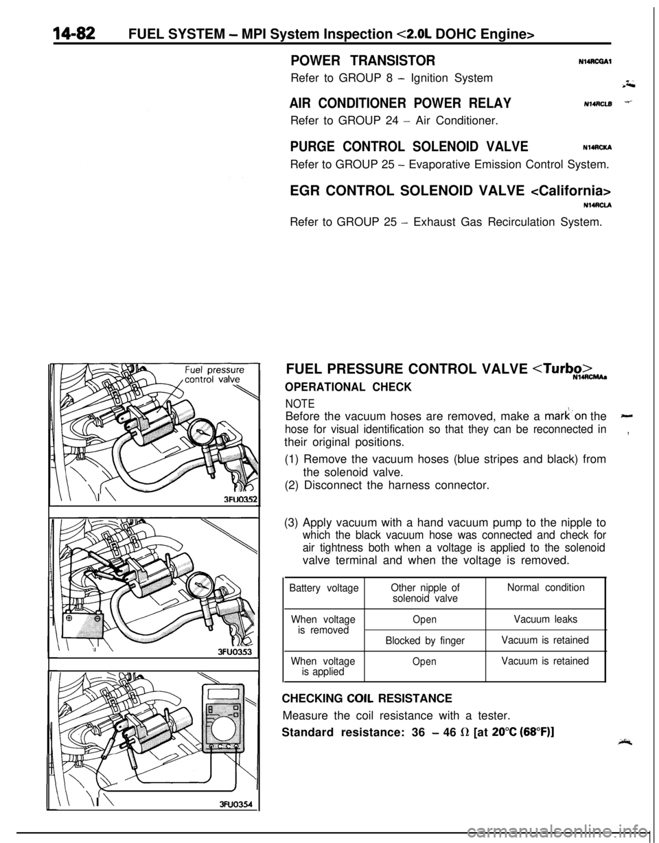
FUEL PRESSURE CONTROL VALVE
NOTEBefore the vacuum hoses are removed, make a mark’on the
-
hose for visual identification so that they can be reconnected in,their original positions.
(1) Remove the vacuum hoses (blue stripes and black) from
the solenoid valve.
(2) Disconnect the harness connector.
(3) Apply vacuum with a hand vacuum pump to the nipple to
which the black vacuum hose was connected and check for
air tightness both when a voltage is applied to the solenoidvalve terminal and when the voltage is removed.
Battery voltageOther nipple of
solenoid valveNormal condition
When voltage
is removed
When voltage
is applied
OpenVacuum leaks
Blocked by fingerVacuum is retained
OpenVacuum is retainedCHECKING
COIL RESISTANCE
Measure the coil resistance with a tester.
Standard resistance: 36
- 46 R [at 20°C (68”F)]