engine MITSUBISHI ECLIPSE 1991 Service Manual
[x] Cancel search | Manufacturer: MITSUBISHI, Model Year: 1991, Model line: ECLIPSE, Model: MITSUBISHI ECLIPSE 1991Pages: 1216, PDF Size: 67.42 MB
Page 869 of 1216
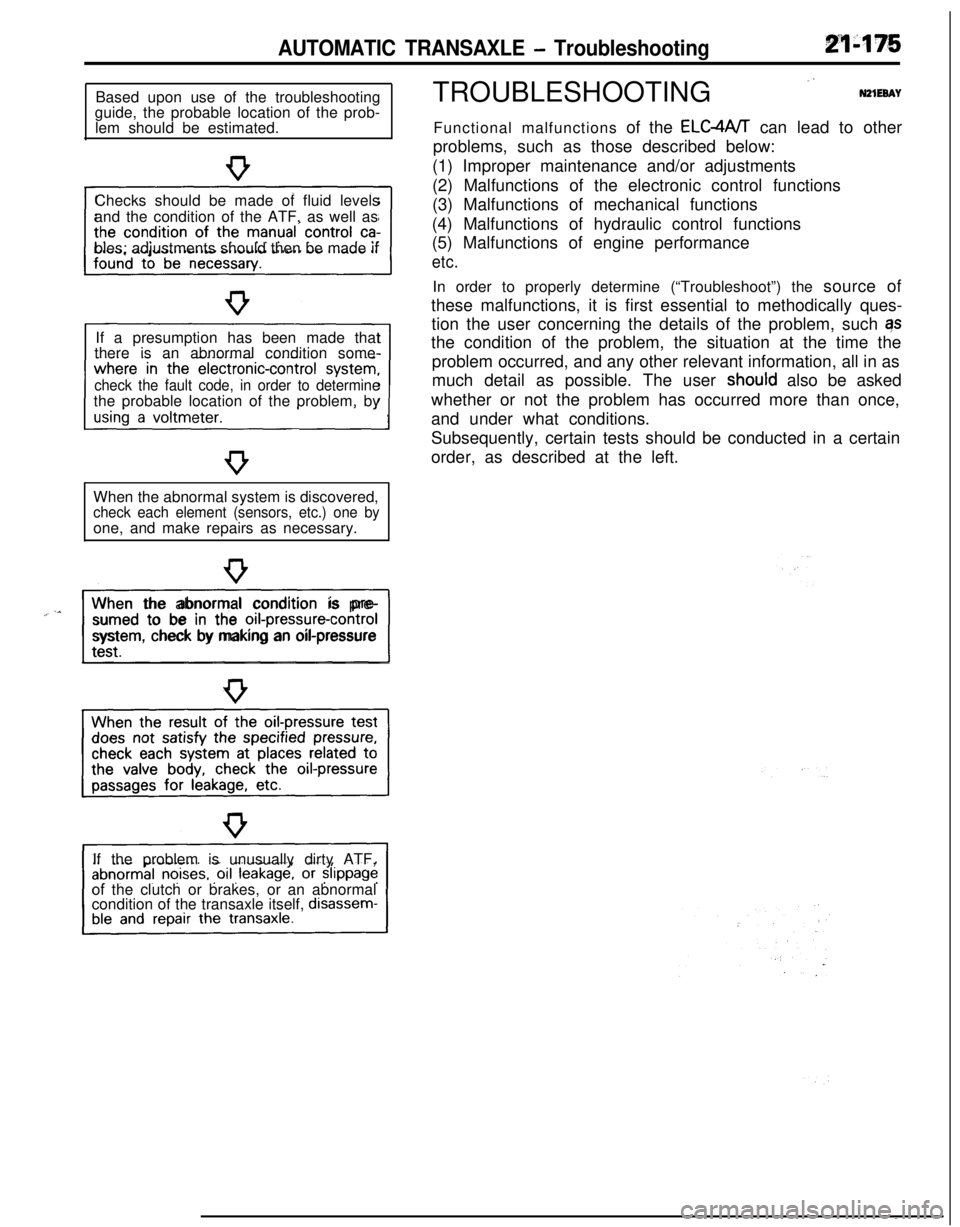
AUTOMATIC TRANSAXLE - TroubleshootingBased upon use of the troubleshooting
guide, the probable location of the prob-
lem should be estimated.
Checks should be made of fluid levels
and the condition of the ATF, as well as
bles; adjustments should then be made if
If a presumption has been made that
there is an abnormal condition some-
check the fault code, in order to determinethe probable location of the problem, by
When the abnormal system is discovered,
check each element (sensors, etc.) one byone, and make repairs as necessary.
“~^II_When the abnormal condition is pre-
sumed to be in the
orI-pressure-controlsystem, check by making an oil-pressure
If the problem is unusually dirty ATF,
of the clutch or brakes, or an abnormal
condition of the transaxle itself,
disassem-TROUBLESHOOTING
”N21EeAYFunctional malfunctions of the ELC4A/T can lead to other
problems, such as those described below:
(1) Improper maintenance and/or adjustments
(2) Malfunctions of the electronic control functions
(3) Malfunctions of mechanical functions
(4) Malfunctions of hydraulic control functions
(5) Malfunctions of engine performance
etc.In order to properly determine (“Troubleshoot”) the source of
these malfunctions, it is first essential to methodically ques-
tion the user concerning the details of the problem, such qs
the condition of the problem, the situation at the time the
problem occurred, and any other relevant information, all in as
much detail as possible. The user
shoutd also be asked
whether or not the problem has occurred more than once,
and under what conditions.
Subsequently, certain tests should be conducted in a certain
order, as described at the left.
Page 879 of 1216
AUTOMATIC TRANSAXLE - Troubleshooting21483
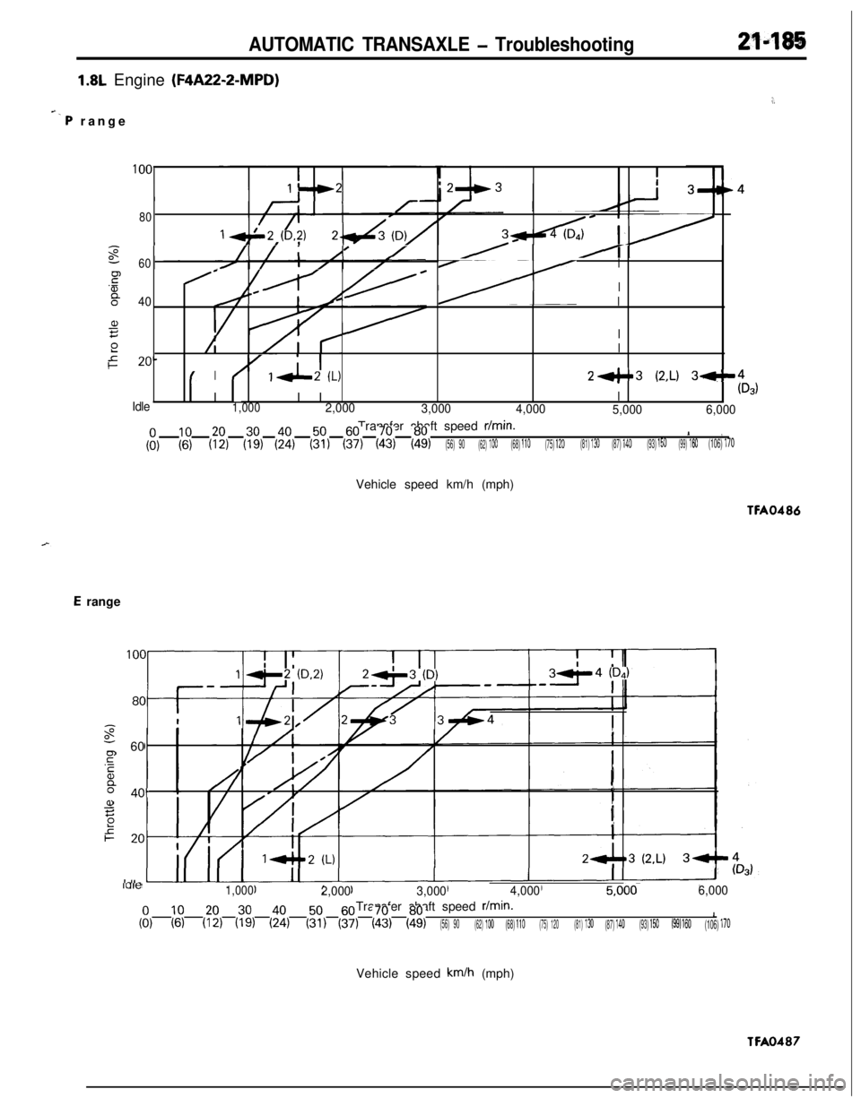
1.8L Engine (F4A22-2-MPD)
+. P range
:,
100II
80c I
I/zb/I/i A’/-60II
Fe
'!zI:I40Jk///@ /'
a,IzI
2Ie20-I
I/' IA (L)24.3 (2,L) 3-14
I(Ds)
IdleI II I1,0002,000
3,000
4,000
5,0006,000Transfer shaft speed
r/min.1I1,
(ii);$(::I(7:)(4:)(::)(i;)(ii)(ii)(56) 90(62) 100(68) 110(75) 120(81) 130(87) 140(93) 150(99) 160(106) 170Vehicle speed km/h (mph)TFA0486
E range
I
- 60I
PI40.
!
a,It:!
ILIlt?1,0002,0003,0004,0005,000~6,000Transfer shaft speed
r/min.1,1I.$1('69(::,(%(%,$7)(i?)(ii,&(56) 90(62) 100(68) 110(75) 120(81) 130(87) 140(93) 150(99) 160(106) 170Vehicle speed
km/h (mph)TFA0487
Page 880 of 1216
21-186AUTOMATIC TRANSAXLE - Troubleshooting
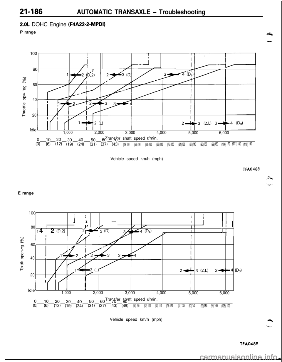
2.0L DOHC Engine (F4A22-2-MPDI)
P range
II
i
-
-z2-I
100I
i
801/ I/
;
P60.-
&
840a,s2
e20I
2"c3 (2.L) 39+4 (DA
Idle1,0002,000
3,0004,000
5,0006,000Transfer shaft speed
r/min.Iiik?66)&(35:)(t;,(ii,(49) 80(56) 90(62) 100(68) 110(75) 120(81) 130(87) 140(93) 150(99) 160(106) 170(111) 180(118) 190Vehicle speed km/h (mph)
TFA0488
E range
100IIIII
I
1I --IiI/80I II/ /Y/I II142(D-2)214 3 (D)4(DAIJ/ /I1
I! I
IIo-/A’III-“1m--c
sI
O"40!al5I
2F24 3(2,L)3-1420I
I1I
ldlelI1,0002,000
3,0004,000
5,0006,000Transfer shaft speed
r/min.I1Iii,('$(:;,(%)(;:)&(:?,(&(::I(56) 90(62) 100(68) 110(75) 120(81) 130(87) 140(93) 150(99) 160(106) 170Vehicle speed km/h (mph)
P3)TFA0489
Page 881 of 1216
AUTOMATIC TRANSAXLE - Troubleshooting
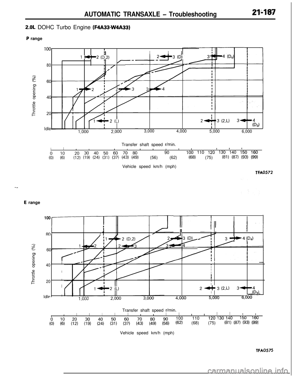
2.0L DOHC Turbo Engine (F4A33-W4A33)
P range
100I
1 .*-2 (6.2,
IIII
80I
I27’3 (2.L)3-I
I$3,
3,000
4,000
5,000
6,000Transfer shaft speed
r/min.
IIIIIIIIII11II
coo, ;fi90
100 110 120 130 140 150 160
(:;j (::j (i:, (?, (!;I (ii, (% (56) (62) (68) (75) (81) (87) (93) (99,Vehicle speed km/h (mph)
TFA0572
E range
l-r
1I
I II
II1
I I-IIIIII-80/IL/IIc
3 --4 !D,)
100
:40I1IaI
EI
I
,o
f20IIIII
I2 +- 3 (2.L)3--I, (4D3,11 nnn'1 nnnA nnn!i nnn6.01Idk
I .vvvL,““”L),““”7,““”-,---~, DOTransfer shaft speed
r/min.
IIIIIIIIIIIIIIIII
(E, (69 (:;, (% (4:) (% (% (ii, (ii, (%100 110
120 130 140150 160
(62) (68) (75) (81) (87) (93, (99,Vehicle speed km/h (mph)
TFA0575
Page 882 of 1216
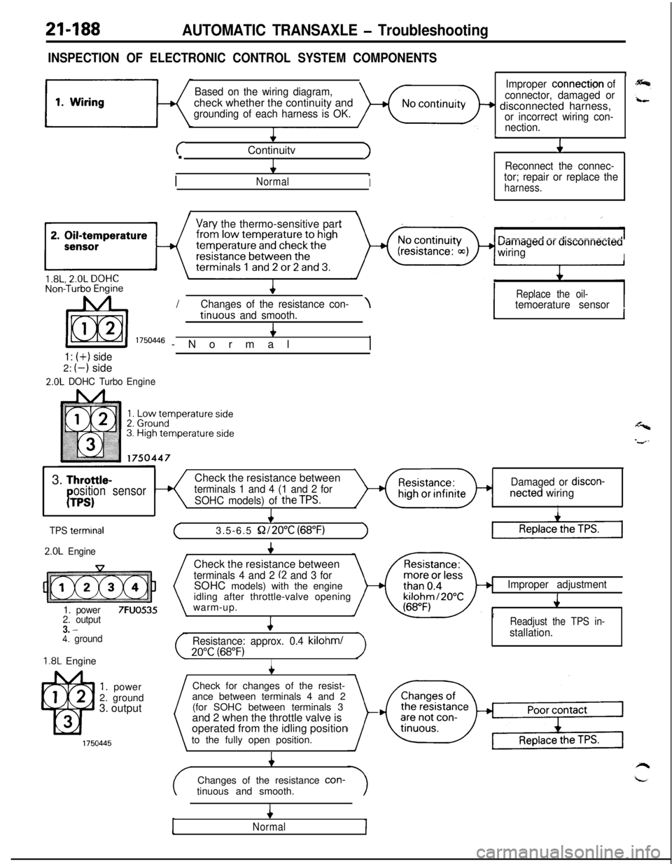
21-188AUTOMATIC TRANSAXLE - Troubleshooting
INSPECTION OF ELECTRONIC CONTROL SYSTEM COMPONENTS
Based on the wiring diagram,check whether the continuity and
grounding of each harness is OK.
+
cContinuitvJ.
4
/
.NormalI
1
Improper connection of
connector, damaged or
+ disconnected harness,or incorrect wiring con-
nection.
L
J1
Reconnect the connec-
tor; repair or replace the
harness.
I\
Vary the thermo-sensitive part
uarriageu ur ursconnecreawiring
I/
IReplace the oil-Chanaes of the resistance con-\temoerature sensortinuo& and smooth.4
I 1750446 -Normal,
1: (+) side2:
(-) side
2.0L DOHC TurboEngine
1I
Y3.
Throttle-Check the resistance betweenosition sensorterminals 1 and 4 (1 and 2 forDamaged or discon-
PTPS)SOHC models) of theTPS.netted wiringI
I
TPS termrnal
2.0L Engine
1. power
7FUO5352. output3. -4. ground
1.8L Engine
1. power
2. ground
3. output
+
(3.5-6.5 S2/2O”C (68°F)1Check the resistance between
terminals 4 and 2 (2 and 3 forSOHC models) with the engine
idling after throttle-valve opening
warm-up.
4
Resistance: approx. 0.4 kilohml
20°C (68°F)I
Improper adjustment
J
’Readjust the TPS in-
stallation.Check for changes of the resist-
ance between terminals 4 and 2
(for SOHC between terminals 3
and 2 when the throttle valve is
operated from the idling position
to the fully open position.
4Changes of the resistance con-
tinuous and smooth.
4
Normal
Page 883 of 1216
AUTOMATIC TRANSAXLE - Troubleshooting21-189
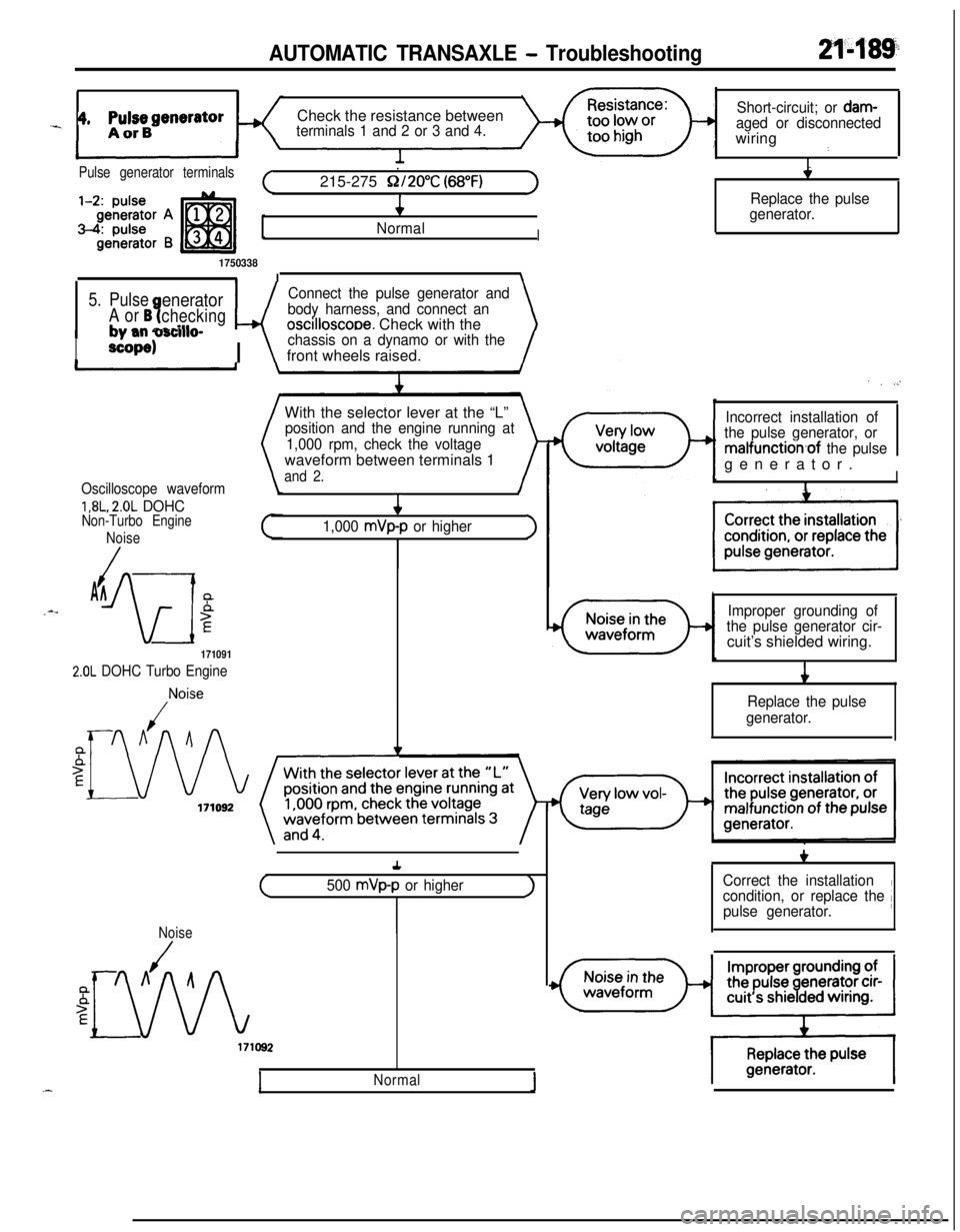
_ 4, ppBgeneratorCheck the resistance betweenterminals 1 and 2 or 3 and 4.Short-circuit; or
dam-aged or disconnectedwiring
:
I
.
4
/
NormalI
1750338II\
Pulse generator terminals.(215-275 Q/2O”C (68°F)1
5. PulseeneratorConnect the pulse generator and
A or B?checkingwbody harness, and connect an
+ mm narillroscilloscooe. Check with the\
I
#, -mm v3nlwdP
scope)I \
chassis on a dynamo or with thefront wheels raised.
With the selector lever at the “L”
position and the engine running at
1,000 rpm, check the voltagewaveform between terminals 1
and 2.
Oscilloscope waveform
1,8L, 2.0L DOHCNon-Turbo Engine
Noise
/AA_--
iw
5E4
1,000 mVp-p or higher>
171091
2.0L DOHC Turbo Engine
,Noise
Replace the pulse
generator.
. . .,’
Incorrect installation of
the pulse generator, or
malfunction,of the pulsegenerator.
II
Improper grounding of
the pulse generator cir-cuit’s shielded wiring.
i
Replace the pulse
generator.+
(500 mVp-p or higherJ
Noise
Normal1
+,I
Correct the installation
condition, or replace the /pulse generator.
Page 885 of 1216
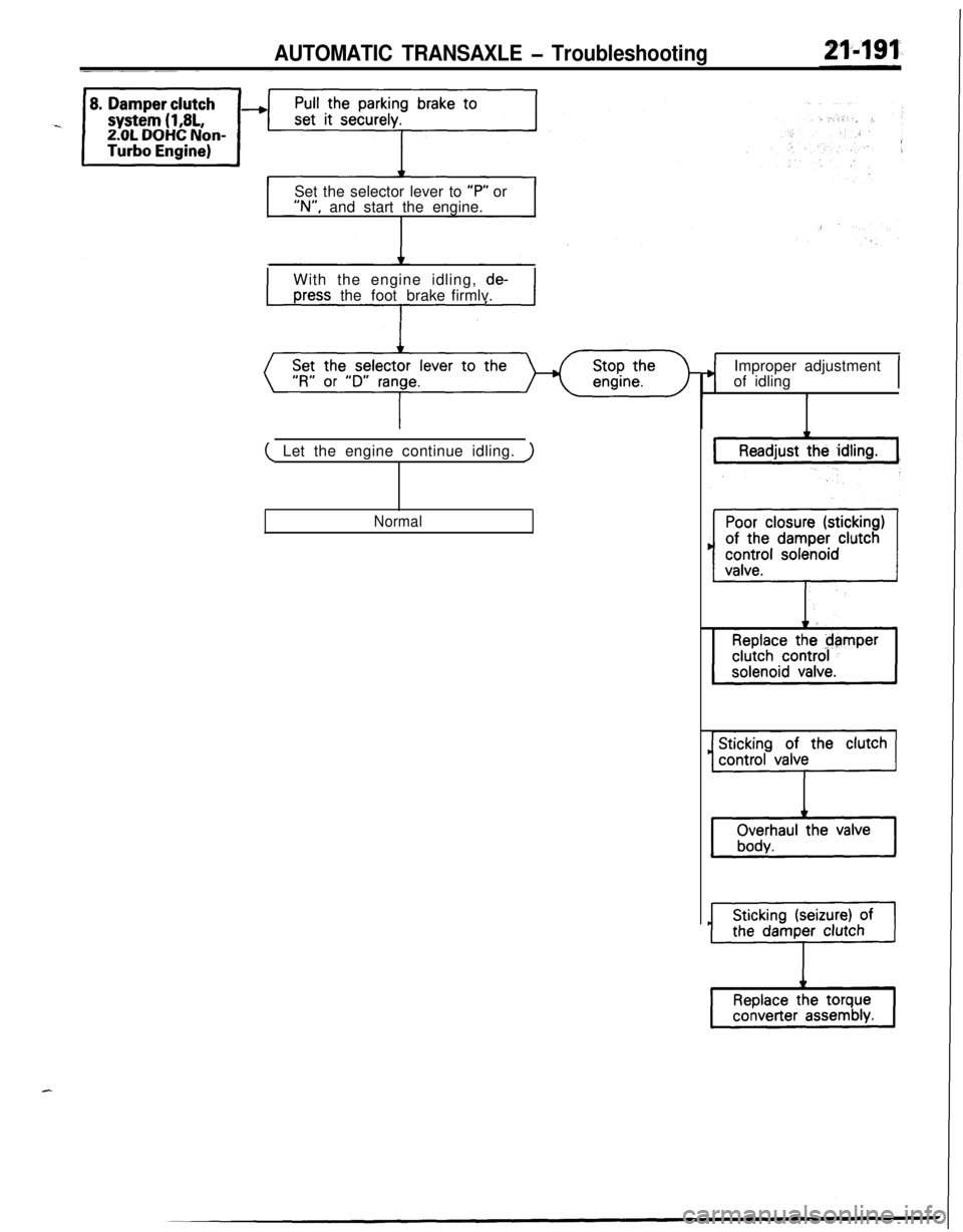
AUTOMATIC TRANSAXLE - TroubleshootingSet the selector lever to “P” or“N”, and start the engine.
IWith the engine idling,
de-
Dress the footbrake firmlv.I
( Let the engine continue idling. )
NormalImproper adjustment
of idling
I
Page 886 of 1216
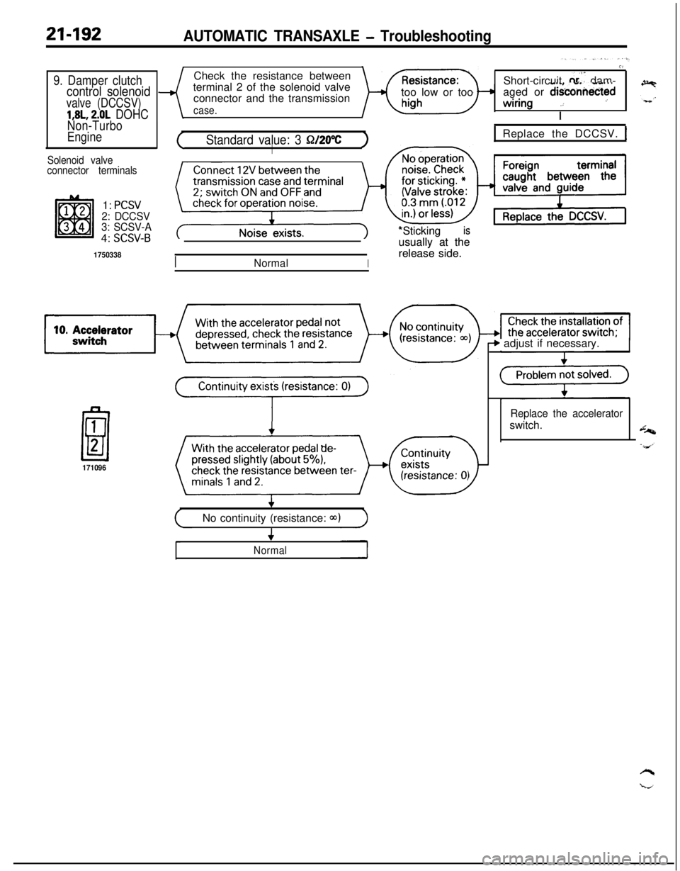
21-192AUTOMATIC TRANSAXLE - Troubleshooting
9. Damper clutchcontrol solenoid
valve (DCCSV)
1,8L, 2.0L DOHC
Non-Turbo
Engine
Solenoid valve
connector terminals1:
PCSV2: DCCSV
3: SCSV-A4:
SCSV-B
1750338Check the resistance between
terminal 2 of the solenoid valve
connector and the transmission
case.too low or too
G’Short-circuit
0,s” dam-
aged or d&connectedwiring
.: ’
I
(Standard value: 3 Q/20%)I
INormalI*Sticking *Sticking
is isusually at the usually at the
release side. release side.
1 Replace the DCCSV. 1
171096
b adjust if necessary.
Replace the acceleratorswitch.
(No continuity (resistance: Q)))4
Normal
Page 888 of 1216
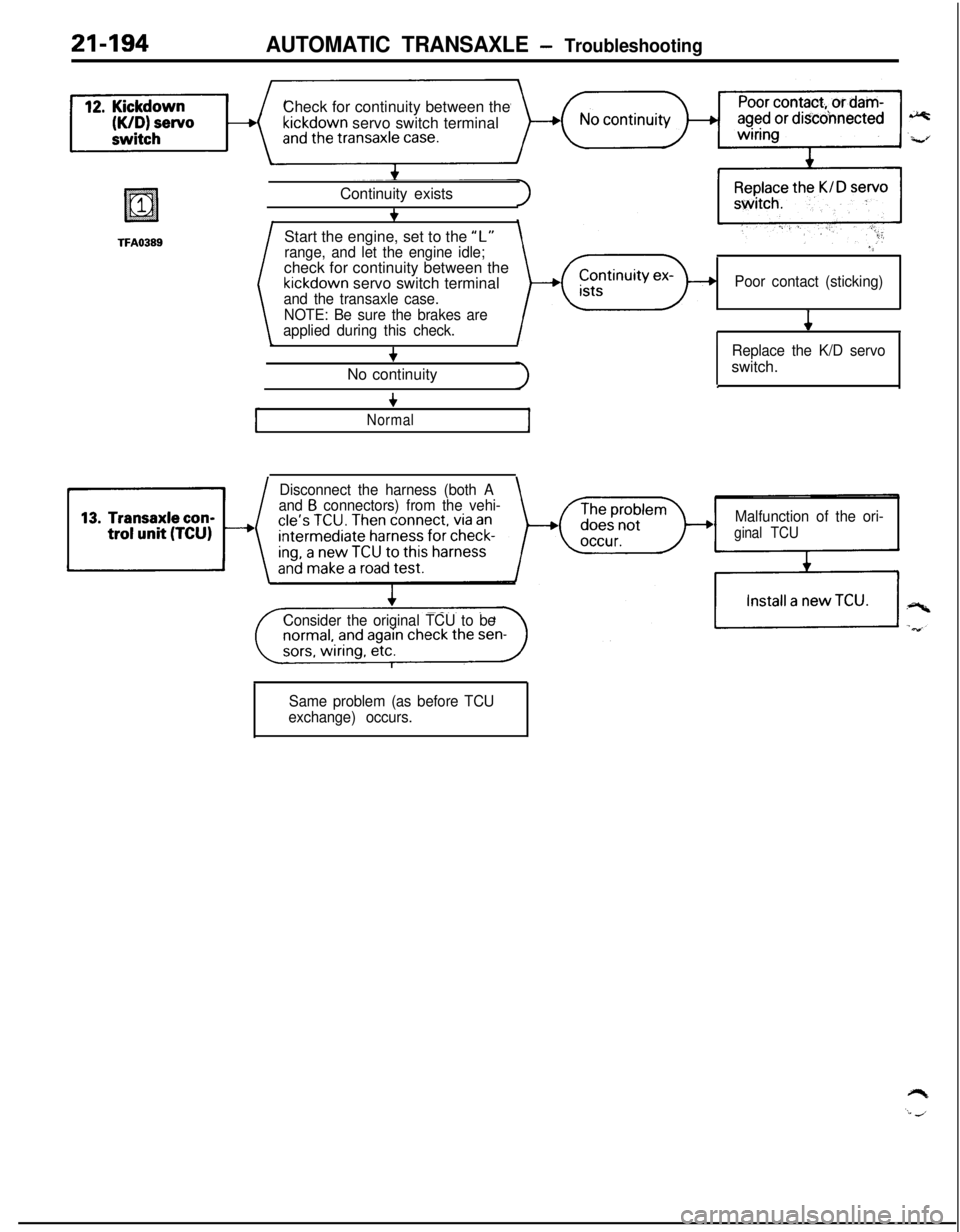
21-194AUTOMATIC TRANSAXLE - TroubleshootingCheck for continuity between the
kickdown servo switch terminal
TFA0389Start the engine, set to the “L”Continuity exists
+
range, and let the engine idle;check for continuity between the
kickdown servo switch terminaland the transaxle case.
NOTE: Be sure the brakes are
applied during this check.
+No continuity
“‘
Poor contact (sticking)
4
Replace the K/D servoswitch.
.
+
Normal
Disconnect the harness (both A
and B connectors) from the vehi-
Malfunction of the ori-
ginal TCU
Consider the original TCU to be
Same problem (as before TCU
exchange) occurs.
Page 889 of 1216
AUTOMATIC TRANSAXLE - Troubleshooting21'495
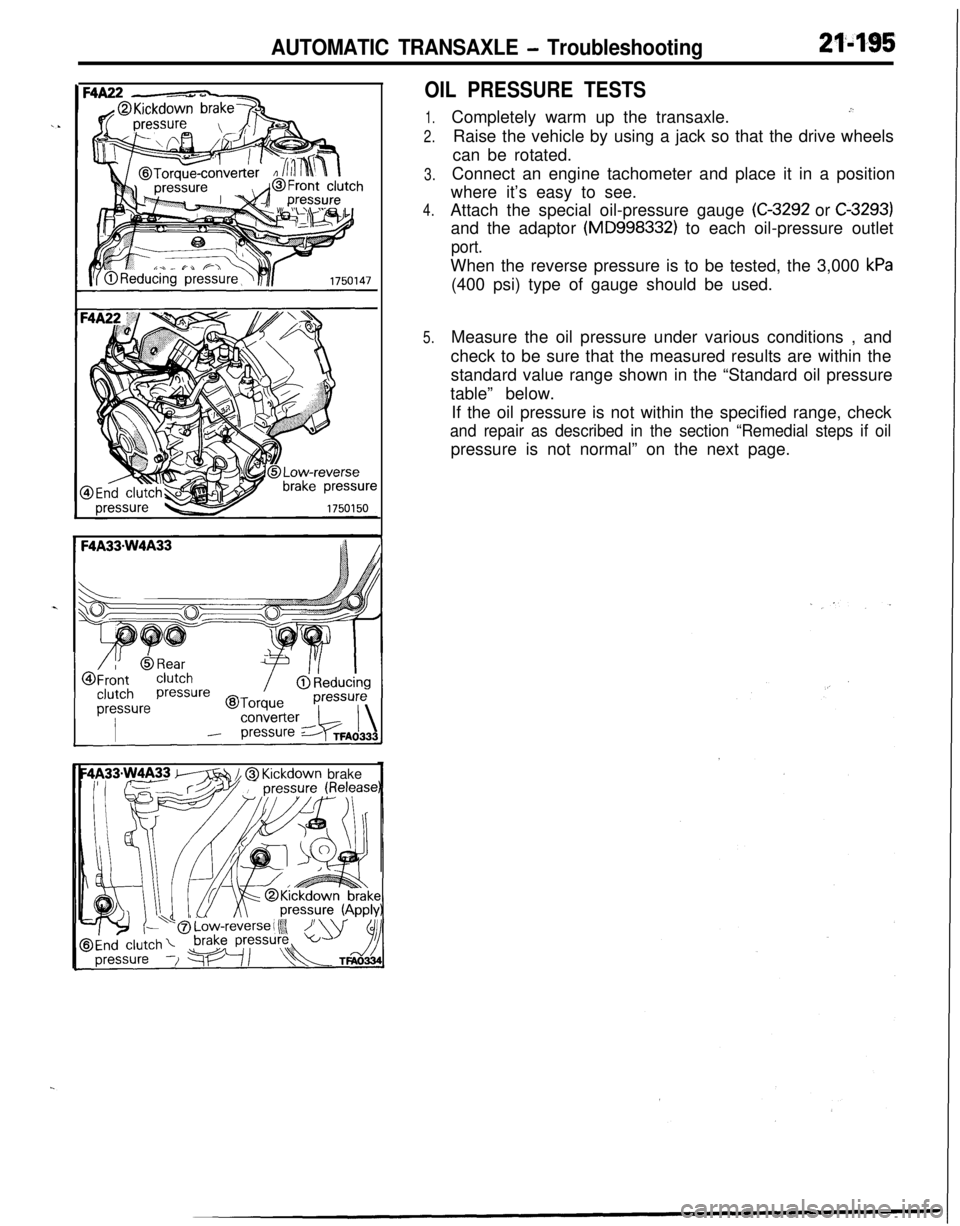
OIL PRESSURE TESTS
1.
2.
3.
4.
5.Completely warm up the transaxle.
.”Raise the vehicle by using a jack so that the drive wheels
can be rotated.
Connect an engine tachometer and place it in a position
where it’s easy to see.
Attach the special oil-pressure gauge
(C-3292 or C-3293)and the adaptor
(MD998332) to each oil-pressure outlet
port.When the reverse pressure is to be tested, the 3,000
kPa(400 psi) type of gauge should be used.
Measure the oil pressure under various conditions , and
check to be sure that the measured results are within the
standard value range shown in the “Standard oil pressure
table” below.
If the oil pressure is not within the specified range, check
and repair as described in the section “Remedial steps if oilpressure is not normal” on the next page.
m // @ Kickdown brake