engine MITSUBISHI ECLIPSE 1991 Service Manual
[x] Cancel search | Manufacturer: MITSUBISHI, Model Year: 1991, Model line: ECLIPSE, Model: MITSUBISHI ECLIPSE 1991Pages: 1216, PDF Size: 67.42 MB
Page 688 of 1216
1 S-40STEERING - Power Steering Oil Pump
SERVICE POINTS OF REMOVAL
Nl8RW2. DISCONNECTION OF RETURN HOSE
(1) Removal the reservoir cap and disconnect the return
hose from the reservoir to drain the fluid.
(2) Jack up the front wheels.
(3) Disconnect the high tension cable and turn the engine
over several times to drain the fluid from the gear box.
3. DISCONNECTION OF SUCTION
HOSE14. PRESSURE
HOSE
Caution
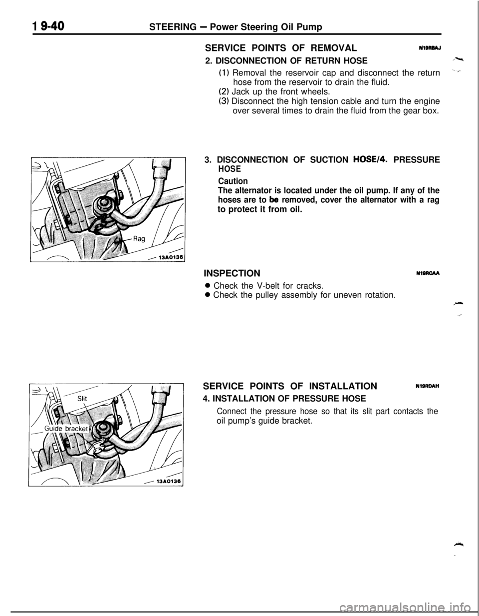
The alternator is located under the oil pump. If any of the
hoses are to
be removed, cover the alternator with a ragto protect it from oil.
INSPECTION
NIRCAA0 Check the V-belt for cracks.0 Check the pulley assembly for uneven rotation.
SERVICE POINTS OF INSTALLATION
4. INSTALLATION OF PRESSURE HOSE
NlSRDAH
Connect the pressure hose so that its slit part contacts theoil pump’s guide bracket.
Page 696 of 1216
21-2MANUAL TRANSAXLE
MANUAL TRANSAXLE
NZlBAAP
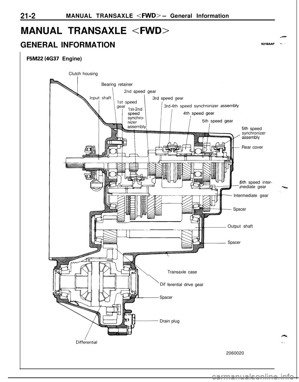
F5M22 (4637 Engine)
Clutch housing
Bearing retainer
2nd speed gear
3rd soeedaear
5th speedsynchronizerassemblv
-----..-.IRear cover
5th speed inter-
mediate gear
Intermediate gear
SpacerOutput shaft
SpacerTransaxle case
\Dif ferential drive gear
Diffelential
Spacer
#&---- Drain plug
2060020
Page 697 of 1216
MANUAL TRANSAXLE
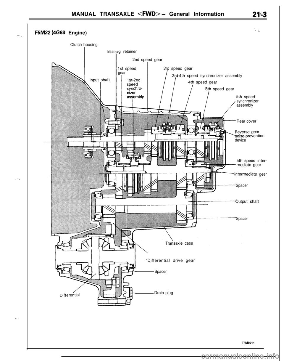
F5M22 (4G63 Engine)
Clutch housing
Bearrin
‘. ;
lg retainer
2nd speed gear
1st speedgear
1 st-2ndspeed
synchro-
I,
nizerassembly
3rd speed gear
3rd-4th speed synchronizer assembly4th speed gear
5th speed gear
5th speed
/
synchronizerassembly
Rear cover
,Reverse gear.norse-preventron
device
SpacerOutput shaft
Spacer‘Differential drive gear
SpacerDrain plug
TFMOOI 1
Page 699 of 1216
MANUAL TRANSAXLE
SPECIFICATIQNS
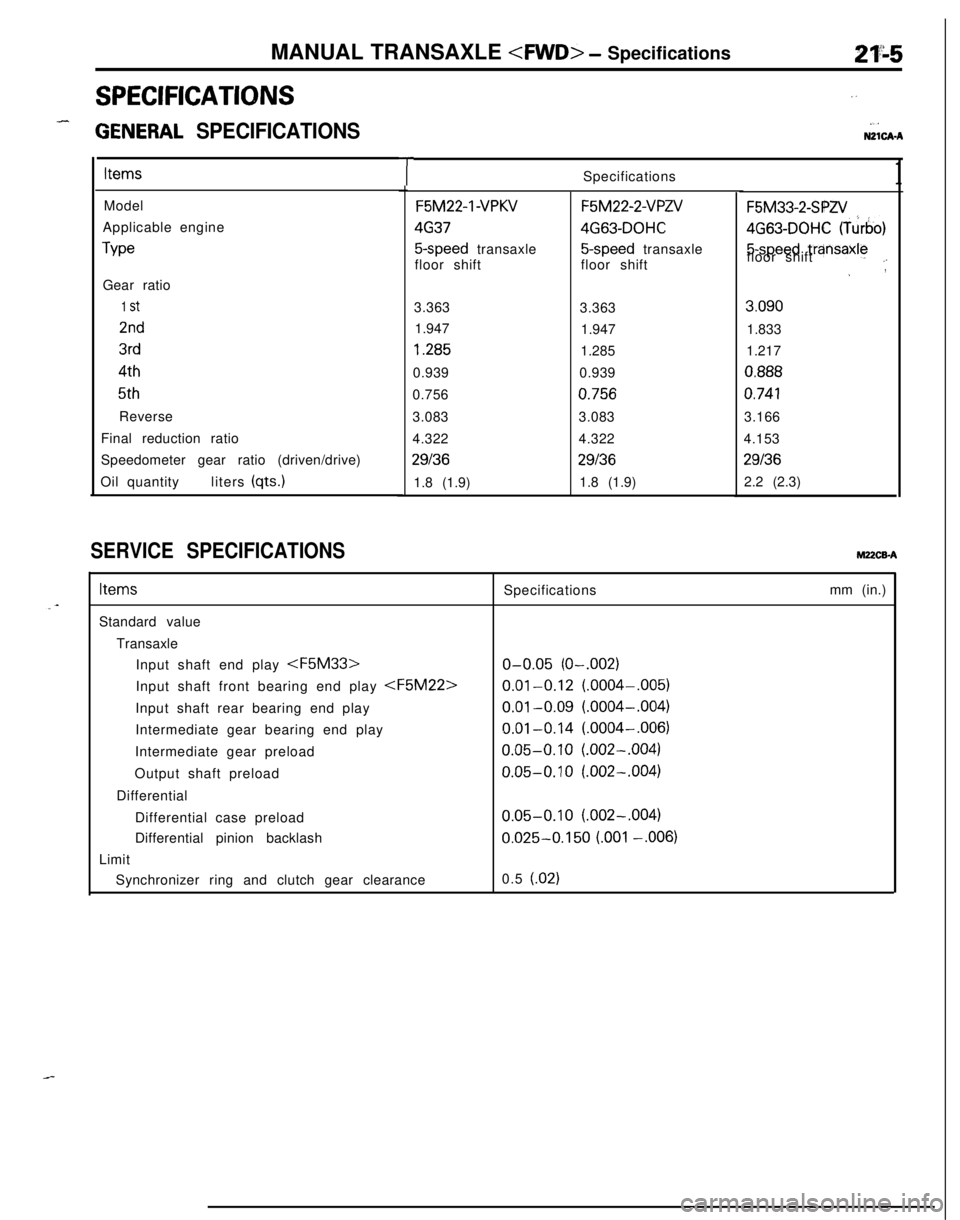
3ENERAL SPECIFICATIONS
ItemsModel
Applicable engine
TypeGear ratio
1 st2nd3rd
4th5th
Reverse
Final reduction ratio
Speedometer gear ratio (driven/drive)
Oil quantityliters (qts.)
SERVICE SPECIFICATIONShl22CBA
”
.,NZlCA-ASpecifications
1TF5M22-1
-VFWF5M22-2-VPZV
46374G63-DOHC
5-speed transaxle5-speed transaxle
floor shiftfloor shift
3.363
3.363
1.947
1.9471.285
1.285
0.9390.939
0.756
0.7563.0833.083
4.3224.322
29136291361.8 (1.9)1.8 (1.9)
F5M33-2-SPA!4G63-DOHC (Turbo)5-speed
trzinsaxlefloor shift.-~,3.090
1.833
1.217
0.888
0.7413.166
4.153
291362.2 (2.3)
ItemsStandard value
Transaxle
Input shaft end play
Intermediate gear bearing end play
Intermediate gear preload
Output shaft preload
Differential
Differential case preload
Differential pinion backlash
LimitSpecifications
o-0.05 (O-.002)
0.01-0.12 (.0004-.005)
0.01-0.09 (.0004-.004)
0.01-0.14 (.0004-,006)
0.05-0.10 (.002-.004)
0.05-0.10 (.002-.004)
0.05-0.10 (.002-.004)
0.025-0.150 LOO1 -.006)mm (in.)
Synchronizer ring and clutch gear clearance0.5 (.02)
Page 706 of 1216
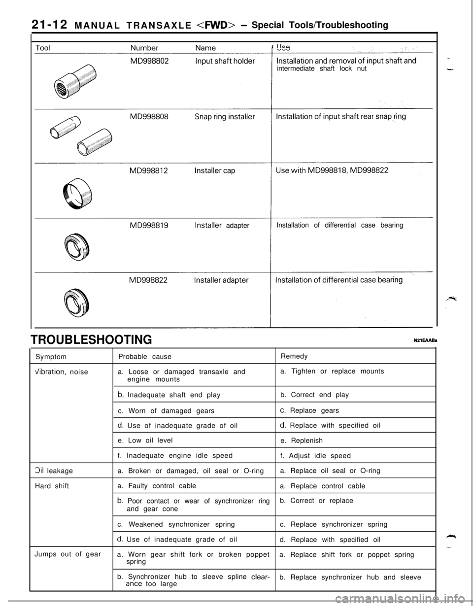
21-12 MANUAL TRANSAXLE
I
IICPintermediate shaft lock nut
MD998819Installer adapterInstallation of differential case bearing
TROUBLESHOOTINGNZlEAABsSymptomVibration, noise
3il leakage
Hard shift
Jumps out of gearProbable causeRemedy
a. Loose or damaged transaxle anda. Tighten or replace mounts
engine mounts
b. Inadequate shaft end playb. Correct end play
c. Worn of damaged gears
c. Replace gears
d. Use of inadequate grade of oild. Replace with specified oil
e. Low oil level
e. Replenish
f. Inadequate engine idle speed
f. Adjust idle speed
a. Broken or damaged, oil seal or O-ringa. Replace oil seal or O-ring
a. Faulty control cable
a. Replace control cable
b. Poor contact or wear of synchronizer ring
and gear coneb. Correct or replace
c. Weakened synchronizer springc. Replace synchronizer spring
d. Use of inadequate grade of oil
d. Replace with specified oil
a. Worn gear shift fork or broken poppet
springa. Replace shift fork or poppet spring
b. Synchronizer hub to sleeve spline
clear-ante too largeb. Replace synchronizer hub and sleeve
Page 713 of 1216
MANUAL TRANSAXLE
TRANSAXLE
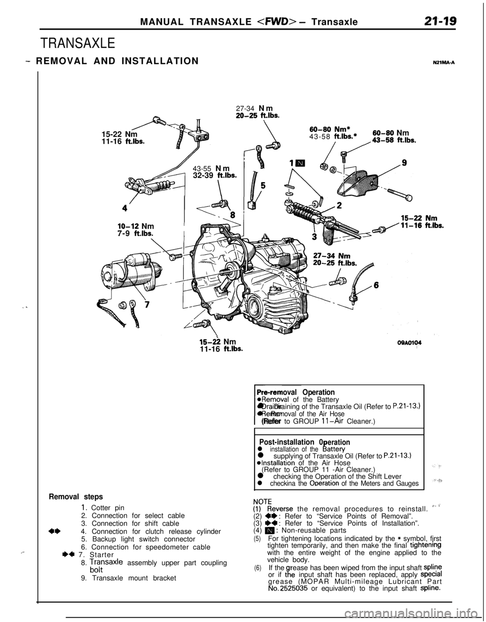
- REMOVAL AND INSTALLATIONNZlMA-A
. .
,-27-34 Nm
20-25 ft.lbs.15-22 Nm
11-16
ft.lbs.43-55 Nm
32-39
ft.lbs.
\
60-80 Nm*43-58 ft.lbs.*60-80 Nm
/da-,, ft.lbs.
lo-12 NmI7-9
ft.lbs.I
15-2: Nm
11-16 ft.lbs.OOAOl~4
Pre-removal Operation@Removal of the Battery
rl Draining of the Transaxle Oil (Refer to
P.21-13.)l Removal of the Air Hose(Refer to GROUP 11-Air Cleaner.)
Post-installation 0erationl installation of theI!attery
l supplying of Transaxle Oil (Refer to P.21-13.)*Installation of the Air Hose
(Refer to GROUP 11 -Air Cleaner.)
l checking the Operation of the Shift Lever
l checkina the Ooeration of the Meters and Gauges
Removal steps
1. Cotter pin
2. Connection for select cable
3. Connection for shift cable
4*4. Connection for clutch release cylinder
5. Backup light switch connector
6. Connection for speedometer cable
I)* 7. Starter
8.
Lfrsaxle assembly upper part coupling
9. Transaxle mount bracket
ZKeverse the removal procedures to reinstall. ” ’(2) W : Refer to “Service Points of Removal”.
(3) ~~ : Refer to “Service Points of Installation”.
(4) m : Non-reusable parts
(5)For tightening locations indicated by the * symbol, fjrst
tighten temporarily, and then make the final tightenrngwith the entire weight of the engine applied to the
vehicle body.
(6)If therease has been wiped from the input shaft spline
or if taeinput shaft has been replaced, apply specralgrease (MOPAR Multi-mileage Lubricant Part
No.2525035 or equivalent) to the input shaft Spline.
Page 763 of 1216
MANUAL TRANSAXLE
2f.46g
\ ,...,
,,, .,
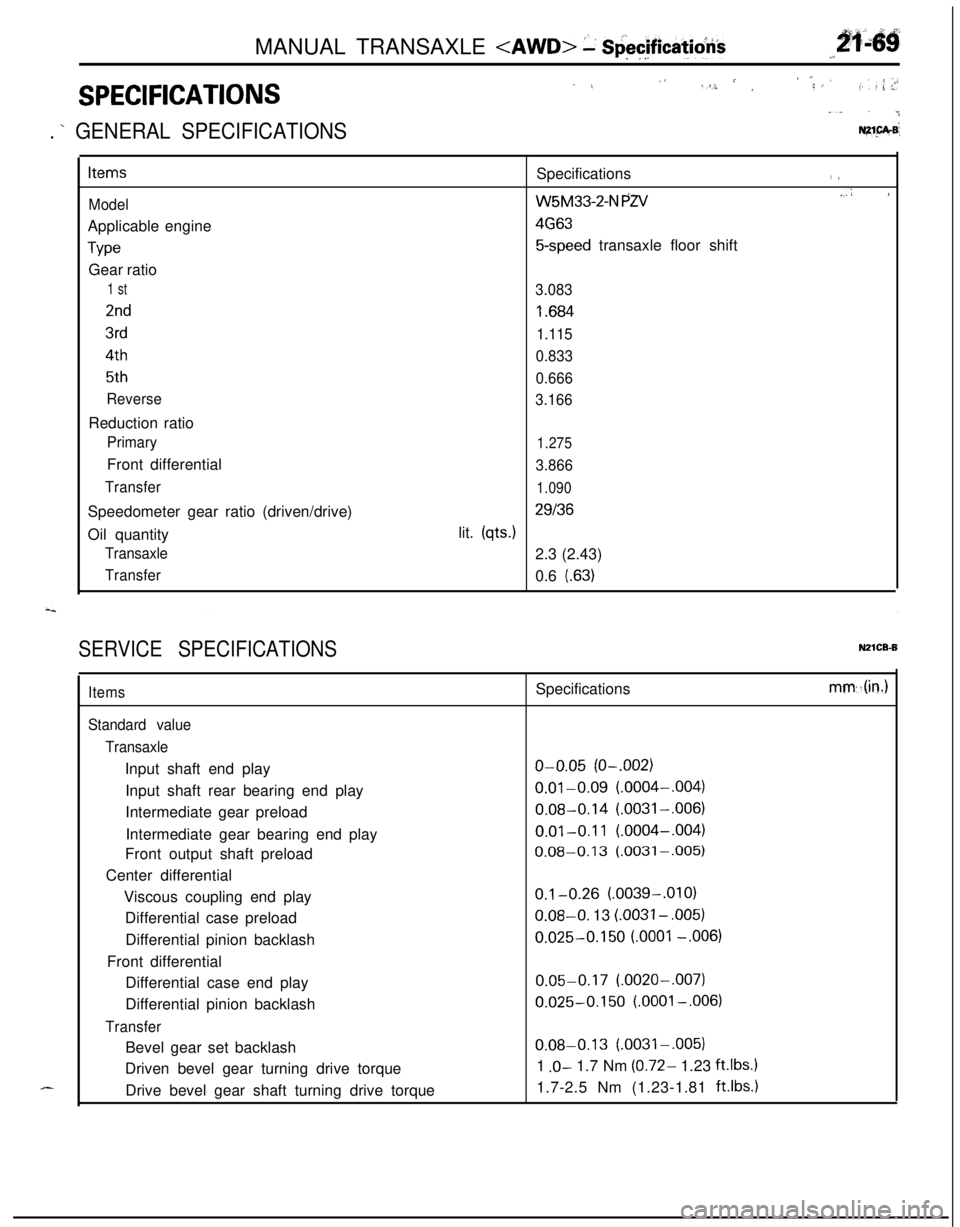
SPECIFICATIONS
1 L,‘S. / ,‘; ,< ’,f. : ,: ; .>r
“. . ..&
. ’ GENERAL SPECIFICATIONSNZ1.pA.B’
Items
ModelApplicable engine
TypeGear ratio
1 st
2nd
3rd
4th
5th
ReverseReduction ratio
PrimaryFront differential
TransferSpeedometer gear ratio (driven/drive)
Oil quantity
Transaxle
TransferSpecifications
(I
W5M33-2-N PZV.,A I
4G63
5-speed transaxle floor shift
3.083
I .684
1.115
0.833
0.666
3.166
1.275
3.866
1.090
29136lit.
(qts.)2.3 (2.43)
0.6
l.63)
SERVICE SPECIFICATIONSN21CB-B
d-...
Items
Standard value
TransaxleInput shaft end play
Input shaft rear bearing end play
Intermediate gear preload
Intermediate gear bearing end play
Front output shaft preload
Center differential
Viscous coupling end play
Differential case preload
Differential pinion backlash
Front differential
Differential case end play
Differential pinion backlash
TransferBevel gear set backlash
Driven bevel gear turning drive torque
Drive bevel gear shaft turning drive torqueSpecifications
o-0.05 (O-.002)
0.01-0.09 (.0004-,004)
0.08-0.14 (.0031-,006)
0.01-0.11 (.0004-,004)
0.08-0.13 (.0031-,005)
0.1-0.26 (.0039-.OlO)0.08-O. 13
LOO31 - ,005)
0.025-0.150 LOO01 -.006)
0.05-0.17 (.0020-,007)
0.025-0.150 (.OOOl-,006)
0.08-0.13 (.0031-.005)
1
.O- 1.7 Nm (0.72- 1.23 ft.lbs.11.7-2.5 Nm (1.23-1.81
ft.lbs.1
mm,.(in.)
Page 776 of 1216
21-82MANUAL TRANSAXLE
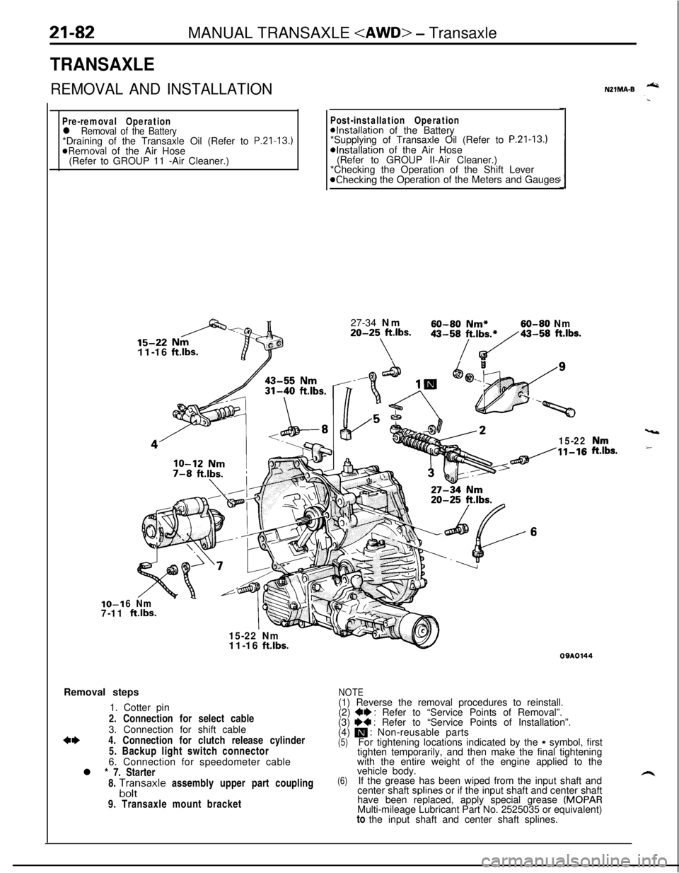
TRANSAXLE
REMOVAL AND INSTALLATION
Pre-removal Operationl Removal of the Battery*Draining of the Transaxle Oil (Refer to P.Zl-13.)
@Removal of the Air Hose
(Refer to GROUP 11 -Air Cleaner.)IO-1
7-1111-16
ftlbs.
Post-installation Operation@Installation of the Battery
*Supplying of Transaxle Oil (Refer to P.21-13.)*Installation of the Air Hose
(Refer to GROUP II-Air Cleaner.)
*Checking the Operation of the Shift Lever
@Checking the Operation of the Meters and Gauges
27-34 Nm
60-60 Nm*60-80 Nm20-25 ft.lbs.
\
43-58/t.,b~43-58 ft.lbs.
15-22
6 Nm
ftlbs.
15-22 Nm
vt11-16
ft.lbs.Removal steps
1. Cotter pin
2. Connection for select cable
3. Connection for shift cable
*I)4. Connection for clutch release cylinder
5. Backup light switch connector
6. Connection for speedometer cable
l * 7. Starter
8.
A;;saxle assembly upper part coupling
9. Transaxle mount bracket
NZlMA-B -
,“rr,s.
09AOl44
NOTE(1) Reverse the removal procedures to reinstall.
(2)
+e : Refer to “Service Points of Removal”.
(3) I)+ : Refer to “Service Points of Installation”.
(4) m : Non-reusable parts(5)For tightening locations indicated by the * symbol, first
tighten temporarily, and then make the final tightening
with the entire weight of the engine applied to the
(6)vehicle body.
If the grease has been wiped from the input shaft and
center shaft splines or if the input shaft and center shaft
have been replaced, apply special grease
(MOPARMulti-mileage Lubricant Part No. 2525035 or equivalent)
to the input shaft and center shaft splines.
Page 853 of 1216
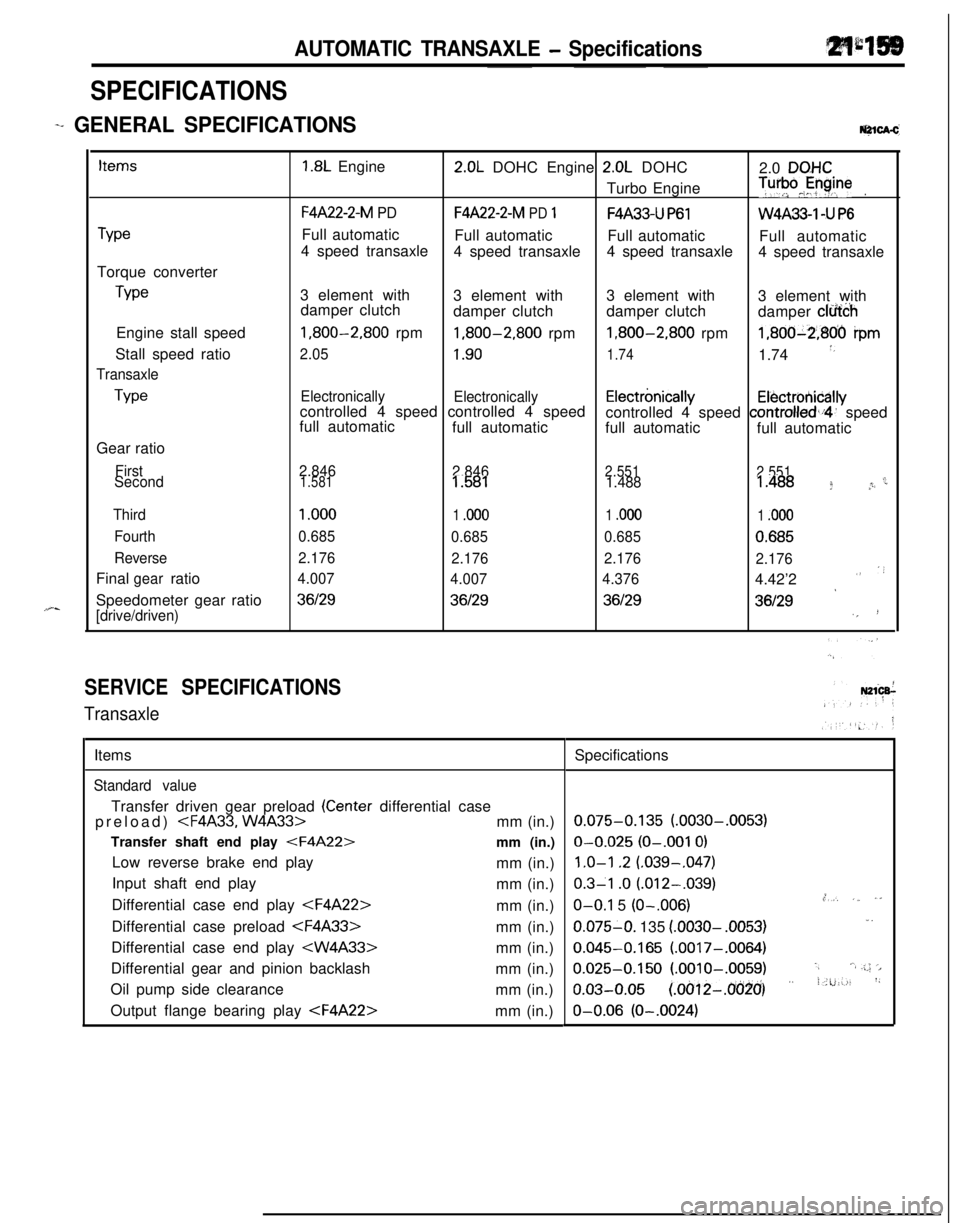
AUTOMATIC TRANSAXLE - Specifications
SPECIFICATIONS
-+ GENERAL [email protected]
TypeTorque converter
TypeEngine stall speed
Stall speed ratio
Transaxle
TypeGear ratio
First
Second
Third
Fourth
ReverseFinal ratio
gearSpeedometer gear ratio
[drive/driven)
1.8L Engine2.0L DOHC Engine 2.0L DOHC
2.0 DQHCTurbo Engine
T”‘pJyine.
F4A22-2-M PDF4A22-2-M PD 1F4A33-U P61W4A33-1 -U P6Full automatic
Full automatic
Full automatic
Full automatic
4 speed transaxle
4 speed transaxle4 speed transaxle
4 speed transaxle
3 element with
3 element with3 element with
3 element with
damper clutch
damper clutchdamper clutch
damper clfi&h
1,800-2,800 rpm1,800-2,800 rpm1,800-2,800 rpm1,800-2,806 ipm
2.051.901.741.74 *,
Electronically
Electronicallycontrolled 4 speed controlled 4 speedElectrbnicallyElectrotiicallyfull automaticcontrolled 4 speed controlled,i4’ speed
full automatic
full automatic
full automatic
2.846
2.8462.551
2.551c1.5811.5811.4881.488 f *r
1 .ooo
1 .ooo1 .ooo1 .ooo
0.685
0.6850.6850.685
2.176
2.1762.176
2.176
4.007
4.0074.3764.42’2
””
*36129361293612936129‘,!
SERVICE SPECIFICATIONS
TransaxleItems
Standard valueTransfer driven gear preload
(Center differential case
preload)
Transfer shaft end play
Low reverse brake end play
mm (in.)
Input shaft end play
mm (in.)
Differential case end play
Differential case preload
Differential case end play
Differential gear and pinion backlash
mm (in.)
Oil pump side clearance
mm (in.)
Output flange bearing play
0.075-0.135 (.0030-.0053)O-0.025
(O-.001 0)
1.0-l .2 (.039-,047)
0.3-l .o (.012-.039).,O-O.1 5 (O-.006),*, ,_ ,”0.075-O. 135
(.0030- .0053)1.
0.045-0.165 (.0017-.0064)
0.025-0.150 (.OOlO-.0059).,‘.a .;.; ‘>
o.03-o.05 (~oo12-~o(j~o’) ” i.u:-., ‘~O-0.06
(O-.0024)
Page 860 of 1216
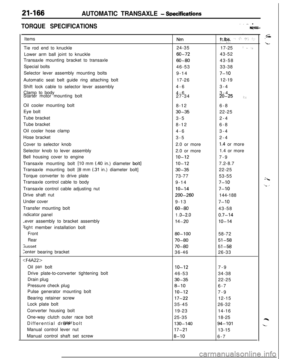
21-166AUTOMATIC TRANSAXLE - SDecifications
TORQUE SPECIFICATIONS,. _ ,,,_ .Nglcc-
ItemsTie rod end to knuckle
Lower arm ball joint to knuckle
Transaxle mounting bracket to transaxle
Special bolts
Selector lever assembly mounting bolts
Automatic seat belt guide ring attaching bolt
Shift lock cable to selector lever assembly
Clamp to body
Starter motor mounting bolt
Oil cooler mounting bolt
Eye bolt
Tube bracket
Tube bracket
Oil cooler hose clamp
Hose bracket
Cover to selector knob
Selector knob to lever assembly
Bell housing cover to engine
Transaxle mounting bolt
[lo mm l.40 in.) diameter bolt]Transaxle mounting bolt
[8 mm I.31 in.) diameter bolt]
Torque converter to drive plate
Transaxle control cable to body
Transaxle control cable adjusting nut
Drive shaft nut
Under cover
Transfer mounting boltndicator panel-ever assembly to bracket assembly
3ight member installation bolt
Front
Rear
;usset
Zenter bearing bracket
:l=4A22>Oil bolt
panDrive plate-to-converter tightening bolt
Drain plug
Pressure check plug
Pulse generator mounting bolt
Bearing retainer screw
Lock plate bolt
Converter housing bolt
One-way clutch outer race bolt
Differential drive bolt
gearManual control lever nut
Manual control shaft set screw
Nm24-35
60-72
60-8046-53
9-14
17-26
4-6
4-6
27-34
8-12
30-353-5
8-12
4-6
3-5
2.0 or more
2.0 or more
10-12
10-12
30-3573-77
9-14
IO-14
200-2609-13
60-80
1 .o-2.0
14-20
80- 100
70-80
70-8036-46
10-1246-53
30-35
8-10
IO-12
17-2235-45
19-23
25-35
130-14017-21
8-10
-.
ft*lgk+ ‘. St. :“.. (1.17-25
I ~. ‘,43-52
43-58
33-38
7-1012-19
3-4
3-4
20-25i::6-8
22-25
2-4
6-8
3-4
2-4
1..4 or more
1.4 or more
7-9
7.2-8.7
22-25
53-55
7-10
7-10144-188
7-1043-58
0.7-14
10-1458-72
51-58
51-5826-33
7-9
34-38
22-25
6-7
7-9
12-15
26-32
14-16
18-25
94-10113-15
6-7