check engine MITSUBISHI ECLIPSE 1991 Manual Online
[x] Cancel search | Manufacturer: MITSUBISHI, Model Year: 1991, Model line: ECLIPSE, Model: MITSUBISHI ECLIPSE 1991Pages: 1216, PDF Size: 67.42 MB
Page 363 of 1216
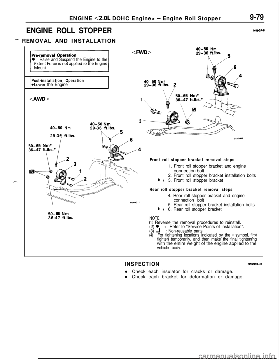
ENGINE <2.0L DOHC Engine> - Engine Roll Stopper
ENGINE ROLL STOPPER
- REMOVAL AND INSTALLATION
9-79
NOSGF-B
X
l Raise and Suspend the Engine to the
40-50Nm29-36ft.lbs.
Post-installation Operation
@Lower the Engine40-50 Nm
1
40-50 Nm3
40-50Nm29-36ft.lbs.
29-36ft.lbs.In/5
/4
\
50-65 Nm
36-47 ftlbs.
Front roll stopper bracket removal steps
1. Front roll stopper bracket and engineconnection bolt
2. Front roll stopper bracket installation bolts
l +3. Front roll stopper bracket
Rear roll stopper bracket removal steps
4. Rear roll stopper bracket and engine
connection bolt
5. Rear roll stopper bracket installation bolts
l +6. Rear roll stopper bracket
NOTE(I) Reverse the removal procedures to reinstall.
(2) l + : Refer to “Service Points of Installation”.(3) q : Non-reusable parts(4)For tightening locations indicated by the * symbol, fjrsttighten temporarily, and then make the final tightenrngwith the entire weight of the engine applied to the
vehicle body.
INSPECTIONNOSGCAHSl Check each insulator for cracks or damage.
l Check each bracket for deformation or damage.
Page 367 of 1216
r-.ENGINE <2.0L DOHC Engine>
- Engine AssemblyS-83
OlA0177
-mpp.-/- --OlA0553
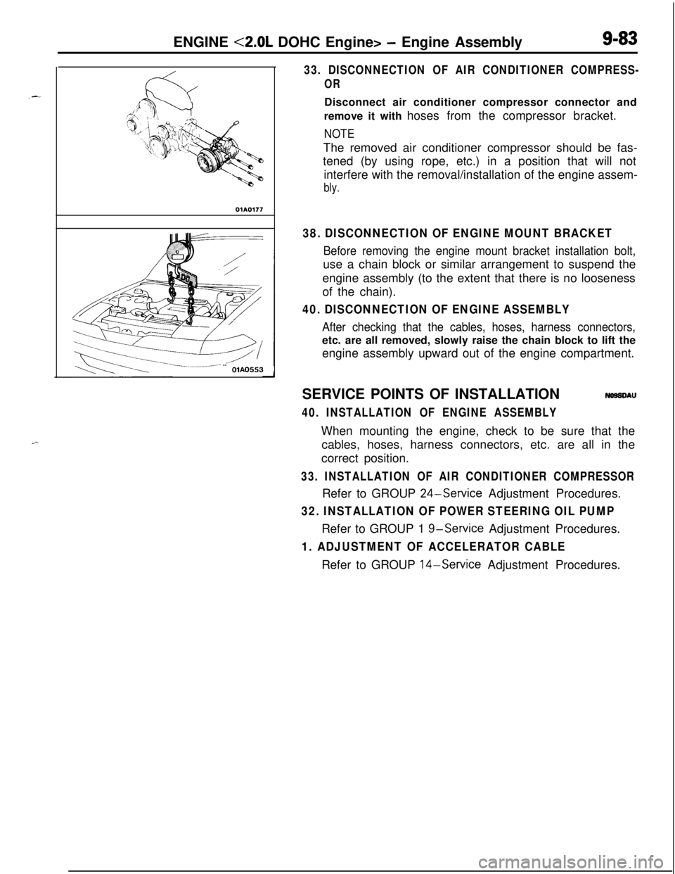
33. DISCONNECTION OF AIR CONDITIONER COMPRESS-
ORDisconnect air conditioner compressor connector and
remove it with hoses from the compressor bracket.
NOTEThe removed air conditioner compressor should be fas-
tened (by using rope, etc.) in a position that will not
interfere with the removal/installation of the engine assem-
bly.
38. DISCONNECTION OF ENGINE MOUNT BRACKET
Before removing the engine mount bracket installation bolt,use a chain block or similar arrangement to suspend the
engine assembly (to the extent that there is no looseness
of the chain).
40. DISCONNECTION OF ENGINE ASSEMBLY
After checking that the cables, hoses, harness connectors,etc. are all removed, slowly raise the chain block to lift the
engine assembly upward out of the engine compartment.
SERVICE POINTS OF INSTALLATION
NOSSDAU
40. INSTALLATION OF ENGINE ASSEMBLYWhen mounting the engine, check to be sure that the
cables, hoses, harness connectors, etc. are all in the
correct position.
33. INSTALLATION OF AIR CONDITIONER COMPRESSORRefer to GROUP
24-Service Adjustment Procedures.
32. INSTALLATION OF POWER STEERING OIL PUMPRefer to GROUP 1
g-service Adjustment Procedures.
1. ADJUSTMENT OF ACCELERATOR CABLERefer to GROUP 14-Service Adjustment Procedures.
Page 369 of 1216
ENGINE <2.0L DOHC Engine> -Camshafts and Camshaft Oil Seals9-85Plastic hammer
Intake side
Exhaust side
Jzzl
(22
Slits
11. REMOVAL OF EXHAUST CAMSHAFT SPROCKET/
12. INTAKE CAMSHAFT SPROCKET(1) Using a wrench at the hexagonal part of the camshaft
(to prevent the crankshaft from turning), loosen the
cramshaft sprocket bolt.
(2) Remove the camshaft sprokets.
13. REMOVAL OF CAMSHAFT OIL SEALSRemove the oil seals using a screwdriver or similar tool.
Caution
Take care not to damage front camshaft bearing cap
and camshaft.
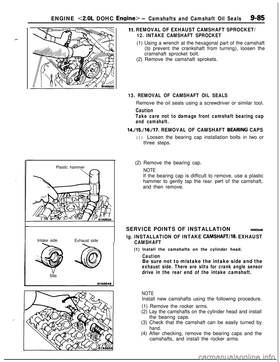
14./15./16./17. REMOVAL OF CAMSHAFT BEARfNG CAPS(1) Loosen the bearing cap installation bolts in two or
three steps.
(2) Remove the bearing cap.
NOTEIf the bearing cap is difficult to remove, use a plastic
hammer to gently tap the rear
.part of the camshaft,
and then remove.
SERVICE POINTS OF INSTALLATIONNO92DAB
lg. INSTALLATION OF INTAKE CAMSHAFT/18. EXHAUST
CAMSHAFT(1) Install the camshafts on the cylinder head.
Caution
Be sure not to mistake the intake side and the
exhaust side. There are slits for crank angle sensor
drive in the rear end of the intake camshaft.
NOTEInstall new camshafts using the following procedure.
(1) Remove the rocker arms.
(2) Lay the camshafts on the cylinder head and install
the bearing caps.
(3) Check that the camshaft can be easily turned by
hand.(4) After checking, remove the bearing caps and the
camshafts, and install the rocker arms.
Page 370 of 1216
9-86ENGINE <2.0L DOHC Engine> -Camshafts and Camshaft Oil Seals
rMD998306qil seal
coatithe
mrenceof the guide.
6EN612Matingmark atMating mark at
llA0361Semi-circular packing
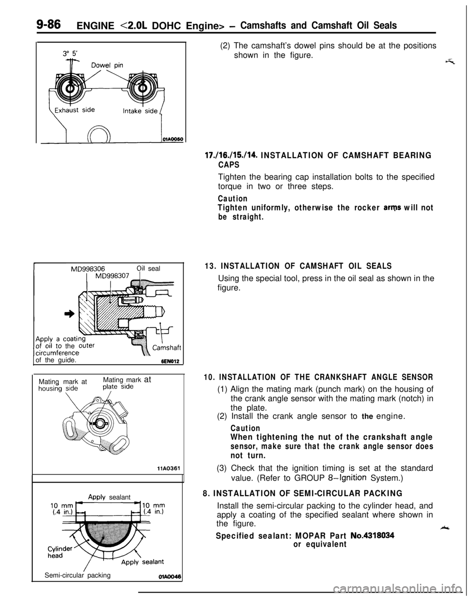
Awlv sealant(2) The camshaft’s dowel pins should be at the positions
shown in the figure.
17./16./15./14. INSTALLATION OF CAMSHAFT BEARING
CAPSTighten the bearing cap installation bolts to the specified
torque in two or three steps.
Caution
Tighten uniformly, otherwise the rocker arms will not
be straight.
13. INSTALLATION OF CAMSHAFT OIL SEALSUsing the special tool, press in the oil seal as shown in the
figure.
_-‘7
10. INSTALLATION OF THE CRANKSHAFT ANGLE SENSOR(1) Align the mating mark (punch mark) on the housing of
the crank angle sensor with the mating mark (notch) in
the plate.
(2) Install the crank angle sensor to the engine.
Caution
When tightening the nut of the crankshaft angle
sensor, make sure that the crank angle sensor does
not turn.(3) Check that the ignition timing is set at the standard
value. (Refer to GROUP
8-Ignition System.)
8. INSTALLATION OF SEMI-CIRCULAR PACKINGInstall the semi-circular packing to the cylinder head, and
apply a coating of the specified sealant where shown in
the figure.
Ak
Specified sealant: MOPAR Part No.4318034
or equivalent
Page 373 of 1216
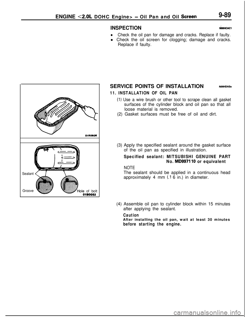
ENGINE <2.0L DOHC Engine> - Oil Pan and Oil Screen9-89
Sealant
Grooveole of bolt
0180052
INSPECTION&SHOW
lCheck the oil pan for damage and cracks. Replace if faulty.l Check the oil screen for clogging; damage and cracks.
Replace if faulty.
SERVICE POINTS OF INSTALLATION
NOSHDASa
11. INSTALLATION OF OIL PAN
(1) Use a wire brush or other tool to scrape clean all gasketsurfaces of the cylinder block and oil pan so that all
loose material is removed.
(2) Gasket surfaces must be free of oil and dirt.
(3) Apply the specified sealant around the gasket surface
of the oil pan as specified in illustration.
Specified sealant: MITSUBISHI GENUINE PART
No.
MD9971 10 or equivalent
NOTEThe sealant should be applied in a continuous head
approximately 4 mm
(.I 6 in.) in diameter.
(4) Assemble oil pan to cylinder block within 15 minutes
after applying the sealant.
CautionAfter installing the oil pan, wait at least 30 minutes
before starting the engine.
Page 382 of 1216
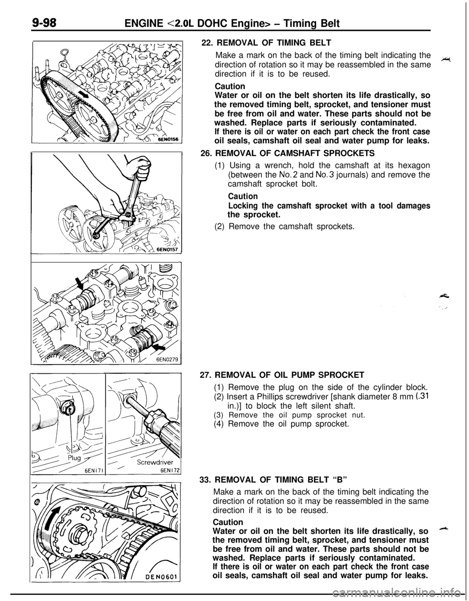
9-98ENGINE <2.0L DOHC Engine> - Timing Belt22. REMOVAL OF TIMING BELT
Make a mark on the back of the timing belt indicating the
direction of rotation so it may be reassembled in the same
~direction if it is to be reused.
Caution
Water or oil on the belt shorten its life drastically, so
the removed timing belt, sprocket, and tensioner must
be free from oil and water. These parts should not be
washed. Replace parts if seriously contaminated.
If there is oil or water on each part check the front caseoil seals, camshaft oil seal and water pump for leaks.
26. REMOVAL OF CAMSHAFT SPROCKETS
(1) Using a wrench, hold the camshaft at its hexagon
(between the No.2 and No.3 journals) and remove the
camshaft sprocket bolt.
Caution
Locking the camshaft sprocket with a tool damagesthe sprocket.
(2) Remove the camshaft sprockets.
127. REMOVAL OF OIL PUMP SPROCKET
(1) Remove the plug on the side of the cylinder block.
(2) Insert a Phillips screwdriver [shank diameter 8 mm
(.31in.)] to block the left silent shaft.
(3) Remove the oil pump sprocket nut.
(4) Remove the oil pump sprocket.
33. REMOVAL OF TIMING BELT “B”
Make a mark on the back of the timing belt indicating the
direction of rotation so it may be reassembled in the same
direction if it is to be reused.
Caution
Water or oil on the belt shorten its life drastically, so
++the removed timing belt, sprocket, and tensioner must
be free from oil and water. These parts should not be
washed. Replace parts if seriously contaminated.
If there is oil or water on each part check the front caseoil seals, camshaft oil seal and water pump for leaks.
Page 383 of 1216
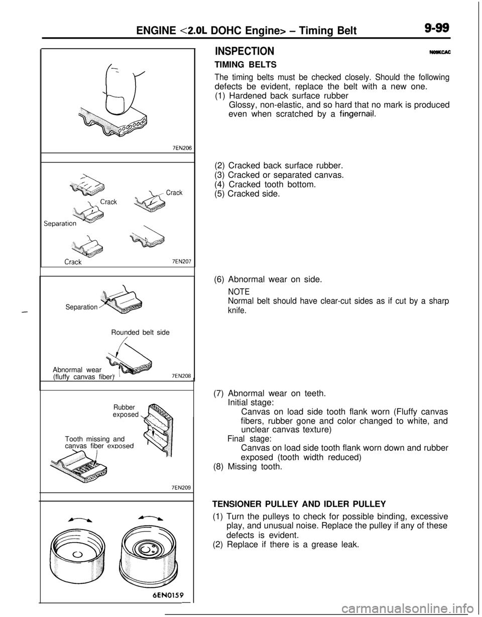
ENGINE <2.0L DOHC Engine> - Timing Belt9-99
-
\
Q+i!il
008ooo
rackCrack
7EN207
SeparationRounded belt side
Abnormal wear
(fluffy canvas fiber)
7EN208
Rubber
exposedTooth missing and
canvas fiber
exoosed
7EN2096EN0159
-
INSPECTIONWSKCACTIMING BELTS
The timing belts must be checked closely. Should the followingdefects be evident, replace the belt with a new one.
(1) Hardened back surface rubber
Glossy, non-elastic, and so hard that no mark is produced
even when scratched by a
fingernai.1.(2) Cracked back surface rubber.
(3) Cracked or separated canvas.
(4) Cracked tooth bottom.
(5) Cracked side.J(6) Abnormal wear on side.
NOTE
Normal belt should have clear-cut sides as if cut by a sharp
knife.(7) Abnormal wear on teeth.
Initial stage:
Canvas on load side tooth flank worn (Fluffy canvas
fibers, rubber gone and color changed to white, and
unclear canvas texture)
Final stage:Canvas on load side tooth flank worn down and rubber
exposed (tooth width reduced)
(8) Missing tooth.
TENSIONER PULLEY AND IDLER PULLEY
(1) Turn the pulleys to check for possible binding, excessive
play, and unusual noise. Replace the pulley if any of these
defects is evident.
(2) Replace if there is a grease leak.
Page 384 of 1216
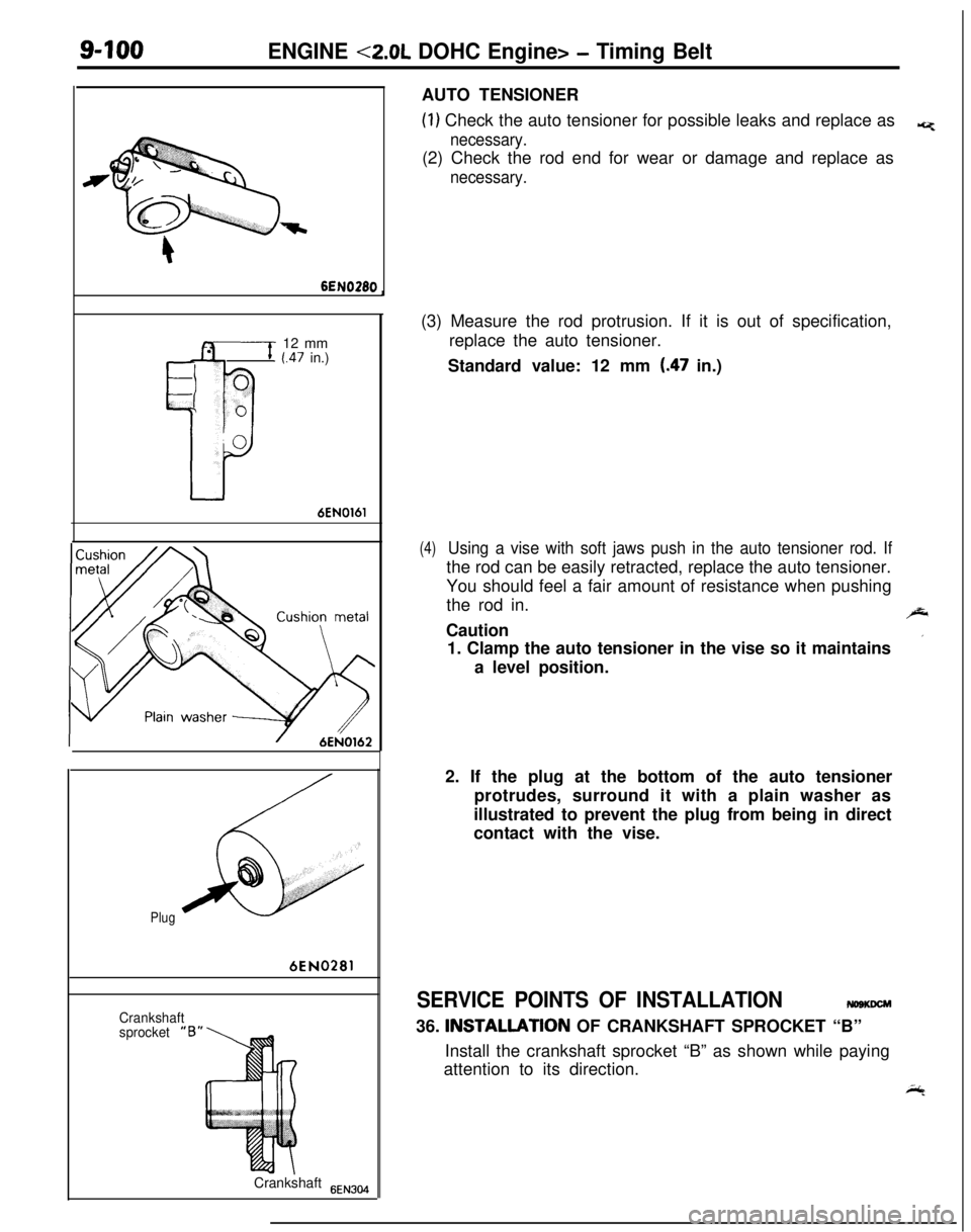
9-100ENGINE <2.0L DOHC Engine> - Timing Belt
6EN028012 mm
(.47 in.)
6EN0161
Plug6EN0281
Crankshaft
sprocket“BJ
Crankshaft
6EN304AUTO TENSIONER
(1) Check the auto tensioner for possible leaks and replace as*
necessary.(2) Check the rod end for wear or damage and replace as
necessary.(3) Measure the rod protrusion. If it is out of specification,
replace the auto tensioner.
Standard value: 12 mm
(.47 in.)
(4)Using a vise with soft jaws push in the auto tensioner rod. Ifthe rod can be easily retracted, replace the auto tensioner.
You should feel a fair amount of resistance when pushing
the rod in.
,J-Caution
’1. Clamp the auto tensioner in the vise so it maintains
a level position.
2. If the plug at the bottom of the auto tensioner
protrudes, surround it with a plain washer as
illustrated to prevent the plug from being in direct
contact with the vise.
SERVICE POINTS OF INSTALLATIONmsmm36. INSTALLATlON OF CRANKSHAFT SPROCKET “B”
Install the crankshaft sprocket “B” as shown while paying
attention to its direction.
i;4
Page 388 of 1216
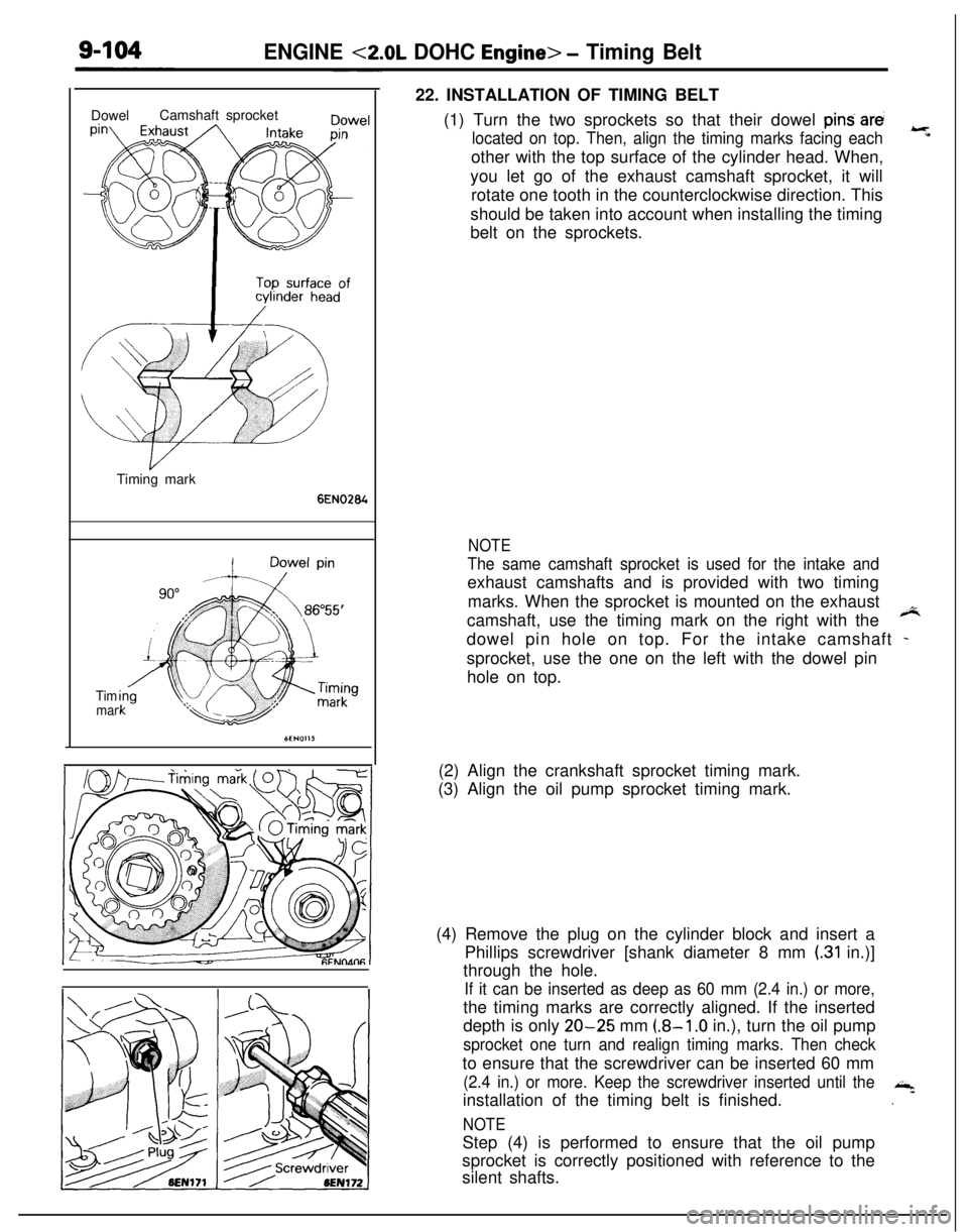
ENGINE <2.0L DOHC Engine> - Timing BeltDowelCamshaft sprocket
Timing mark
6EN0264
Tim
mar22. INSTALLATION OF TIMING BELT
(1) Turn the two sprockets so that their dowel
pind arti
located on top. Then, align the timing marks facing each
-
*other with the top surface of the cylinder head. When,
you let go of the exhaust camshaft sprocket, it will
rotate one tooth in the counterclockwise direction. This
should be taken into account when installing the timing
belt on the sprockets.
NOTE
The same camshaft sprocket is used for the intake andexhaust camshafts and is provided with two timing
marks. When the sprocket is mounted on the exhaust
camshaft, use the timing mark on the right with the
*dowel pin hole on top. For the intake camshaft
-sprocket, use the one on the left with the dowel pin
hole on top.
(2) Align the crankshaft sprocket timing mark.
(3) Align the oil pump sprocket timing mark.
(4) Remove the plug on the cylinder block and insert a
Phillips screwdriver [shank diameter 8 mm
(.31 in.)]
through the hole.
If it can be inserted as deep as 60 mm (2.4 in.) or more,the timing marks are correctly aligned. If the inserted
depth is only
20-25 mm (.8-l .O in.), turn the oil pump
sprocket one turn and realign timing marks. Then checkto ensure that the screwdriver can be inserted 60 mm
(2.4 in.) or more. Keep the screwdriver inserted until theinstallation of the timing belt is finished.,+
.
NOTEStep (4) is performed to ensure that the oil pump
sprocket is correctly positioned with reference to the
silent shafts.
Page 389 of 1216
ENGINE <2.0L DOHC Engine> - Timing Belt9405
I
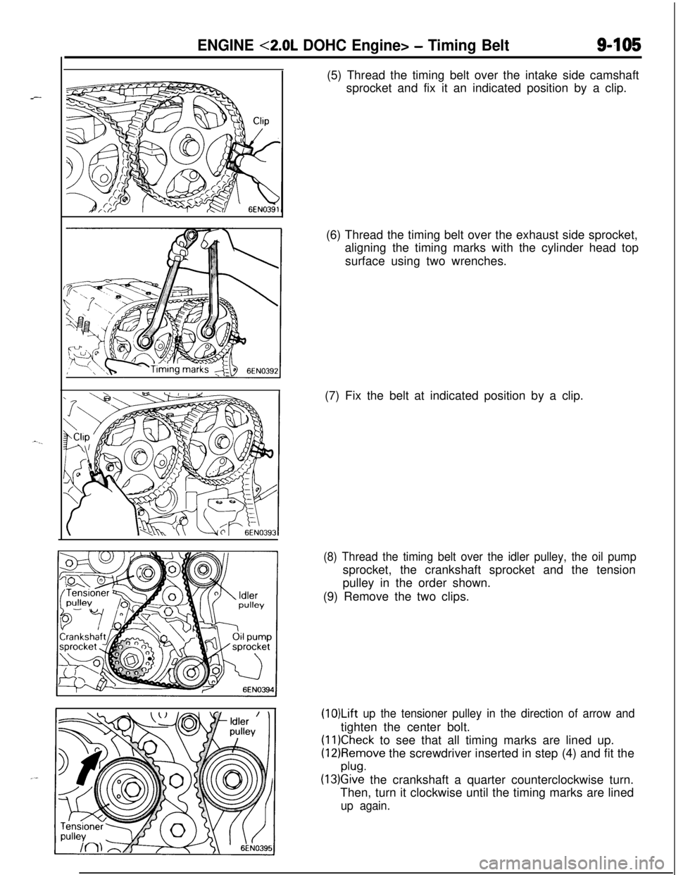
P(5) Thread the timing belt over the intake side camshaft
sprocket and fix it an indicated position by a clip.
(6) Thread the timing belt over the exhaust side sprocket,
aligning the timing marks with the cylinder head top
surface using two wrenches.
(7) Fix the belt at indicated position by a clip.
(8) Thread the timing belt over the idler pulley, the oil pumpsprocket, the crankshaft sprocket and the tension
pulley in the order shown.
(9) Remove the two clips.
(1O)Lift up the tensioner pulley in the direction of arrow andtighten the center bolt.
(11)Check to see that all timing marks are lined up.
(12)Remove the screwdriver inserted in step (4) and fit the
plug.
(13)Give the crankshaft a quarter counterclockwise turn.
Then, turn it clockwise until the timing marks are lined
up again.