MITSUBISHI ENDEAVOR 2004 Service Repair Manual
ENDEAVOR 2004
MITSUBISHI
MITSUBISHI
https://www.carmanualsonline.info/img/19/57105/w960_57105-0.png
MITSUBISHI ENDEAVOR 2004 Service Repair Manual
Trending: module location, engine gasket, belt, catalytic converter, automatic transmission fluid, radio, airbag
Page 2881 of 3870
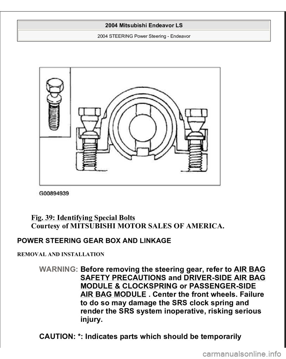
Fig. 39: Identifying Special Bolts
Courtesy of MITSUBISHI MOTOR SALES OF AMERICA.
POWER STEERING GEAR BOX AND LINKAGE REMOVAL AND INSTALLATION
WARNING:Before removing the steering gear, refer to AIR BAG
SAFETY PRECAUTIONS
and DRIVER
-SIDE AIR BAG
MODULE & CLOCKSPRING
or PASSENGER
-SIDE
AIR BAG MODULE
. Center the front wheels. Failure
to do so may damage the SRS clock spring and
render the SRS system inoperative, risking serious
injury.
CAUTION: *: Indicates parts which should be temporarily
2004 Mitsubishi Endeavor LS
2004 STEERING Power Steering - Endeavor
Page 2882 of 3870
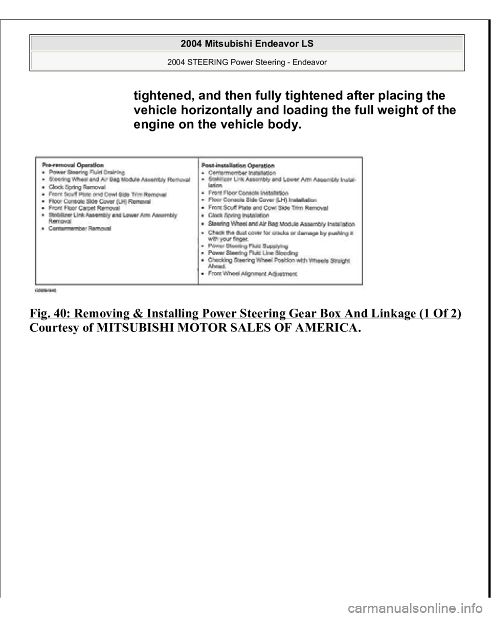
Fig. 40: Removing & Installing Power Steering Gear Box And Linkage (1 Of 2)Courtes
y of MITSUBISHI MOTOR SALES OF AMERICA
.
tightened, and then fully tightened after placing the
vehicle horizontally and loading the full weight of the
engine on the vehicle body.
2004 Mitsubishi Endeavor LS
2004 STEERING Power Steering - Endeavor
Page 2883 of 3870
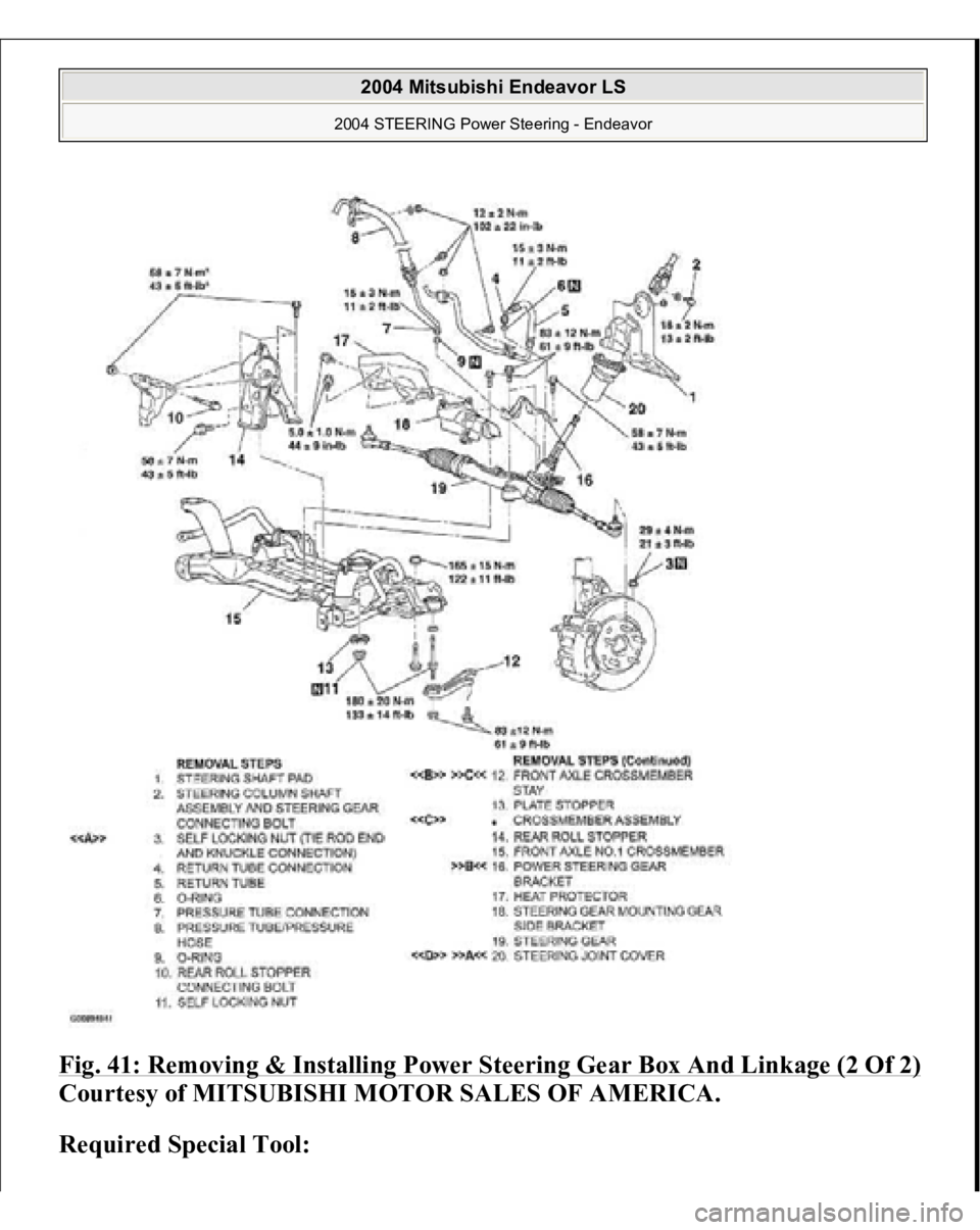
Fig. 41: Removing & Installing Power Steering Gear Box And Linkage (2 Of 2)Courtesy of MITSUBISHI MOTOR SALES OF AMERICA.
Required Special Tool:
2004 Mitsubishi Endeavor LS
2004 STEERING Power Steering - Endeavor
Page 2884 of 3870
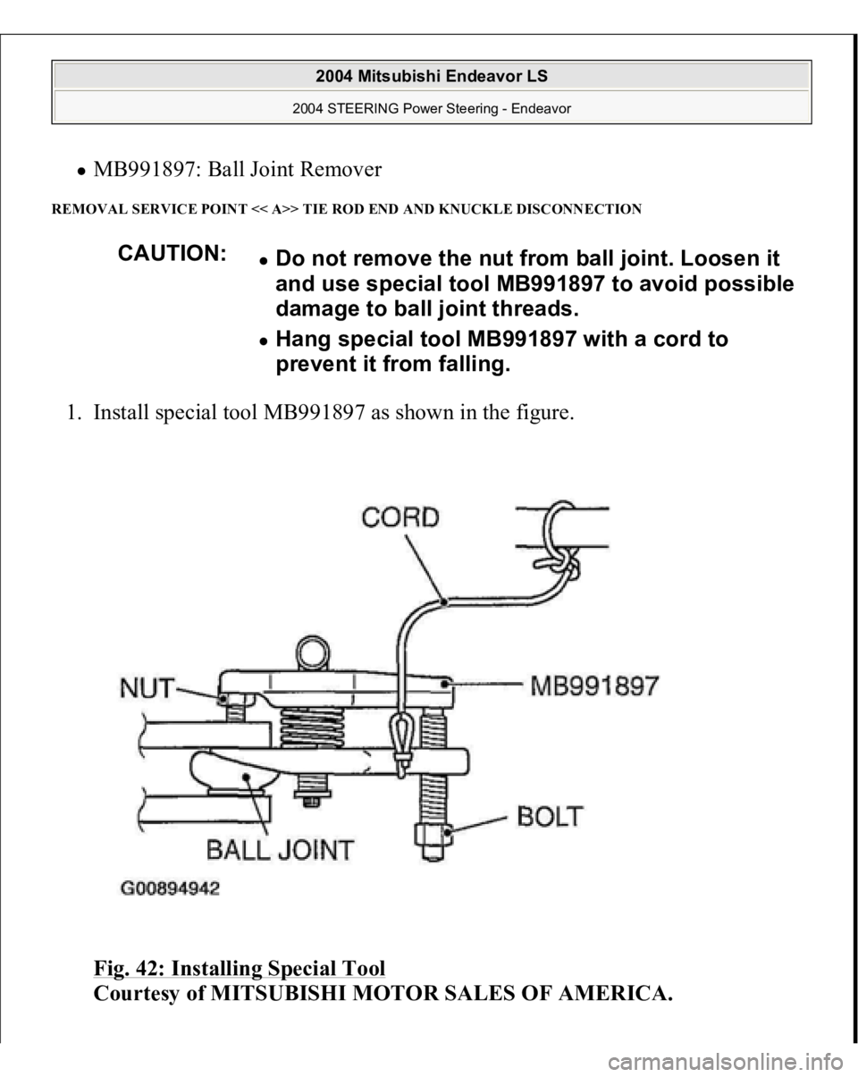
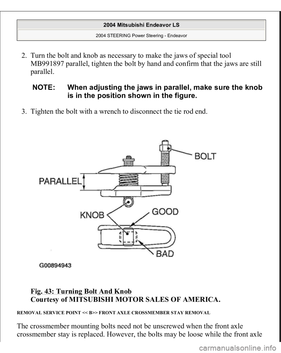
MB991897: Ball Joint Remover
REMOVAL SERVICE POINT << A>> TIE ROD END AND KNUCKLE DISCONNECTION 1. Install special tool MB991897 as shown in the figure.
Fig. 42: Installing Special Tool
Courtesy of MITSUBISHI MOTOR SALES OF AMERICA.
CAUTION:
Do not remove the nut from ball joint. Loosen it
and use special tool MB991897 to avoid possible
damage to ball joint threads. Hang special tool MB991897 with a cord to
prevent it from falling.
2004 Mitsubishi Endeavor LS
2004 STEERING Power Steering - Endeavor
Page 2885 of 3870
2. Turn the bolt and knob as necessary to make the jaws of special tool
MB991897 parallel, tighten the bolt by hand and confirm that the jaws are still
parallel.
3. Tighten the bolt with a wrench to disconnect the tie rod end.
Fig. 43: Turning Bolt And Knob
Courtesy of MITSUBISHI MOTOR SALES OF AMERICA.
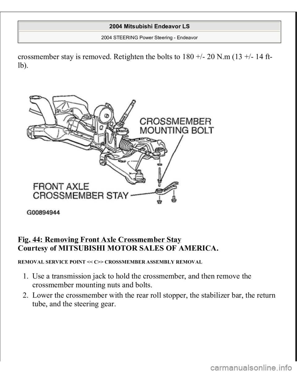
REMOVAL SERVICE POINT << B>> FRONT AXLE CROSSMEMBER STAY REMOVAL The crossmember mounting bolts need not be unscrewed when the front axle
crossmember stay is replaced. However, the bolts may be loose while the front axle
NOTE: When adjusting the jaws in parallel, make sure the knob
is in the position shown in the figure.
2004 Mitsubishi Endeavor LS
2004 STEERING Power Steering - Endeavor
Page 2886 of 3870
crossmember stay is removed. Retighten the bolts to 180 +/- 20 N.m (13 +/- 14 ft-
lb).
Fig. 44: Removing Front Axle Crossmember Stay
Courtesy of MITSUBISHI MOTOR SALES OF AMERICA.
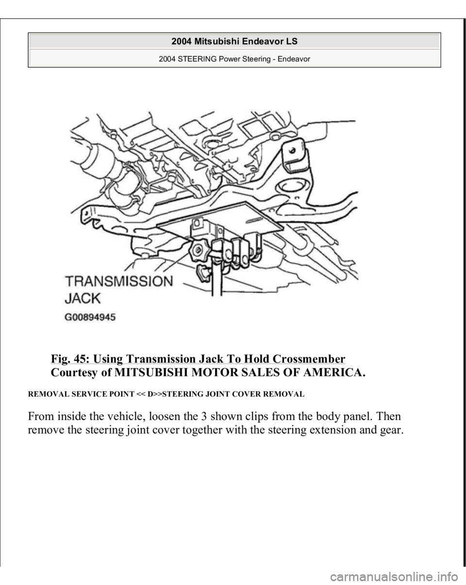
REMOVAL SERVICE POINT << C>> CROSSMEMBER ASSEMBLY REMOVAL 1. Use a transmission jack to hold the crossmember, and then remove the
crossmember mounting nuts and bolts.
2. Lower the crossmember with the rear roll stopper, the stabilizer bar, the return
tube, and the steerin
g gear.
2004 Mitsubishi Endeavor LS
2004 STEERING Power Steering - Endeavor
Page 2887 of 3870
Fig. 45: Using Transmission Jack To Hold Crossmember
Courtesy of MITSUBISHI MOTOR SALES OF AMERICA.
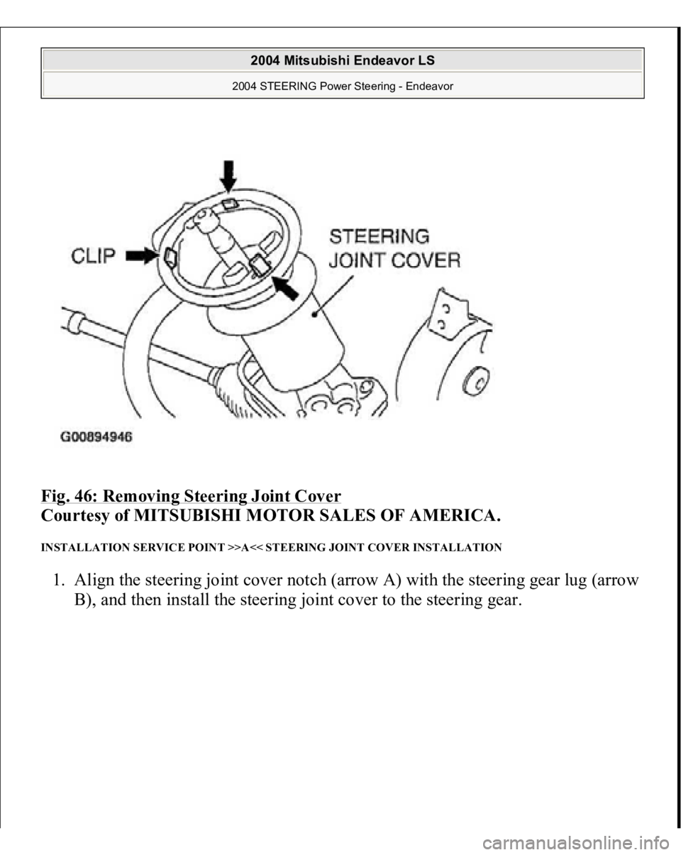
REMOVAL SERVICE POINT << D>>STEERING JOINT COVER REMOVAL From inside the vehicle, loosen the 3 shown clips from the body panel. Then
remove the steering joint cover together with the steering extension and gear.
2004 Mitsubishi Endeavor LS
2004 STEERING Power Steering - Endeavor
Page 2888 of 3870
Fig. 46: Removing Steering Joint Cover
Courtesy of MITSUBISHI MOTOR SALES OF AMERICA.
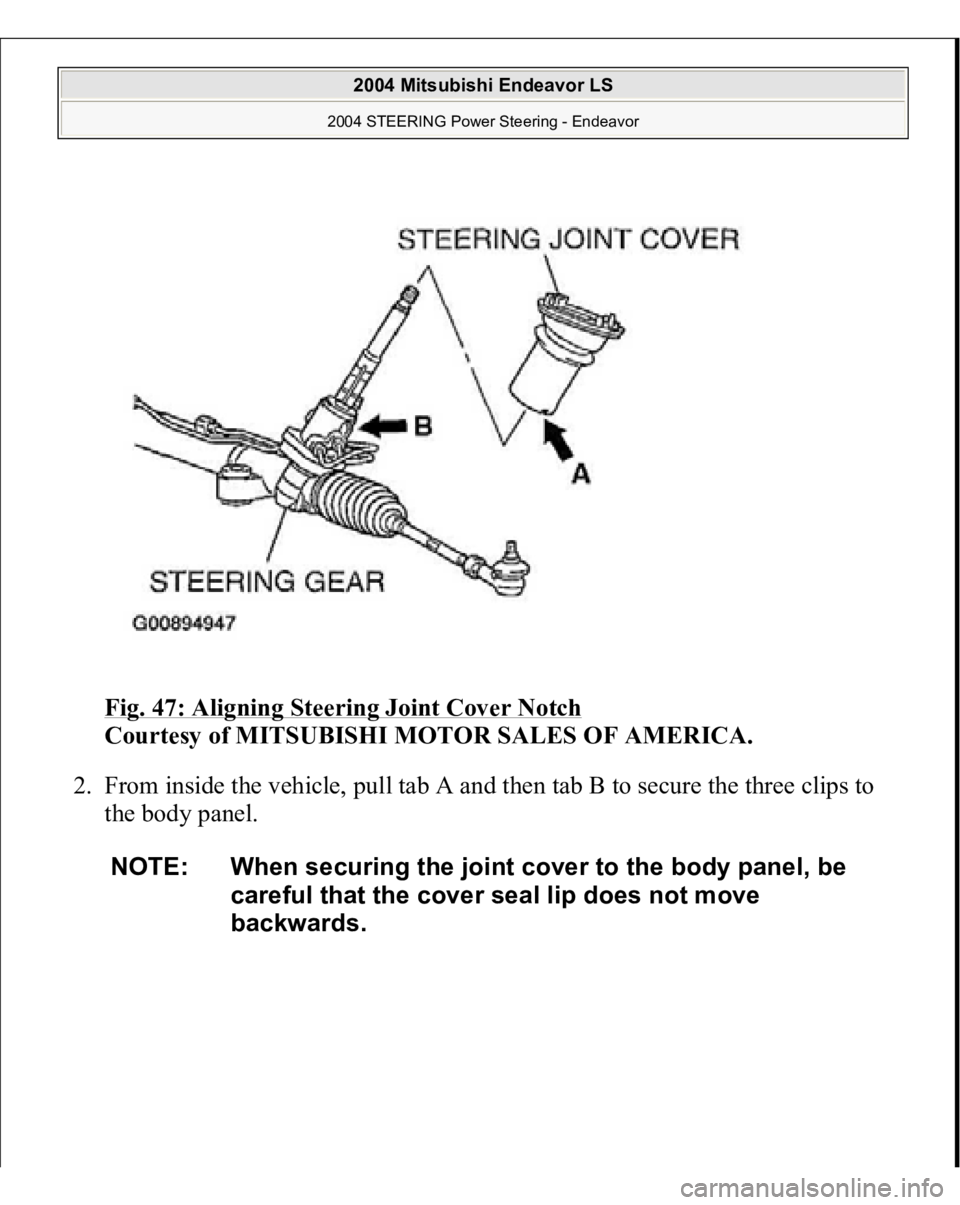
INSTALLATION SERVICE POINT >>A<< STEERING JOINT COVER INSTALLATION 1. Align the steering joint cover notch (arrow A) with the steering gear lug (arrow
B
), and then install the steerin
g joint cover to the steerin
g gear.
2004 Mitsubishi Endeavor LS
2004 STEERING Power Steering - Endeavor
Page 2889 of 3870
Fig. 47: Aligning Steering Joint Cover Notch
Courtesy of MITSUBISHI MOTOR SALES OF AMERICA.
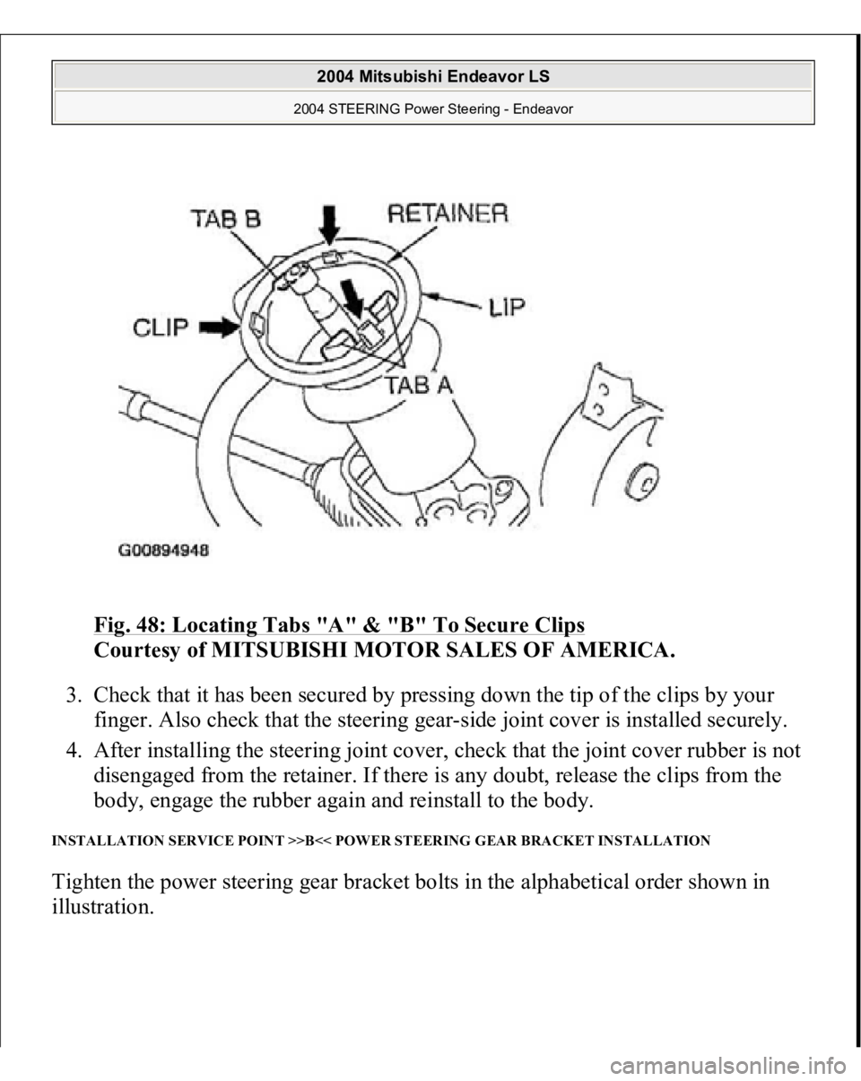
2. From inside the vehicle, pull tab A and then tab B to secure the three clips to
the body panel.
NOTE: When securing the joint cover to the body panel, be
careful that the cover seal lip does not move
backwards.
2004 Mitsubishi Endeavor LS
2004 STEERING Power Steering - Endeavor
Page 2890 of 3870
Fig. 48: Locating Tabs "A" & "B" To Secure Clips
Courtesy of MITSUBISHI MOTOR SALES OF AMERICA.
3. Check that it has been secured by pressing down the tip of the clips by your
finger. Also check that the steering gear-side joint cover is installed securely.
4. After installing the steering joint cover, check that the joint cover rubber is not
disengaged from the retainer. If there is any doubt, release the clips from the
body, engage the rubber again and reinstall to the body.
INSTALLATION SERVICE POINT >>B<< POWER STEERING GEAR BRACKET INSTALLATION Tighten the power steering gear bracket bolts in the alphabetical order shown in
illustration.
2004 Mitsubishi Endeavor LS
2004 STEERING Power Steering - Endeavor
Trending: service interval, module location, rims, sunroof jam, crankshaft pulley, set clock, lights
