MITSUBISHI ENDEAVOR 2004 Service Repair Manual
ENDEAVOR 2004
MITSUBISHI
MITSUBISHI
https://www.carmanualsonline.info/img/19/57105/w960_57105-0.png
MITSUBISHI ENDEAVOR 2004 Service Repair Manual
Trending: Service engine light, Filter, warning lights, transmission oil, check engine light, transmission, Figure 37
Page 2861 of 3870
C (122 - 140°F).
3. The engine should be idling.
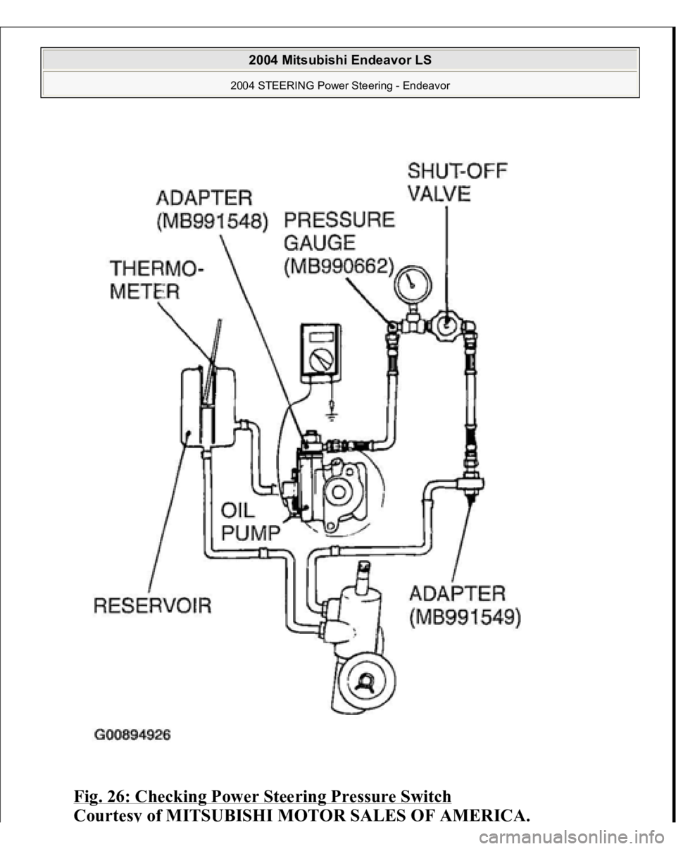
4. Disconnect the connector for the oil pressure switch, and place an ohmmeter at
the switch.
5. Gradually close the shut-off valve of the pressure gauge and increase the
hydraulic pressure, then check whether or not the hydraulic pressure that
activates the switch is the standard value.
Standard value: 18 - 2.4 MPa (261 - 348 psi)
6. Gradually open the shut-off valve and reduce the hydraulic pressure; then
check whether or not the hydraulic pressure that deactivates the switch is the
standard value.
Standard value: 0.8 - 2.4 MPa (116 - 348 psi)
7. Remove the special tools MB991548, MB990662 and MB991549, and then
tighten the pressure tube flare nut to the specified torque.
Tightening torque: 15 +/- 3 N.m (11 +/- 2 ft-lb)
8. Bleed the system. (Refer to POWER STEERING SYSTEM AIR BLEEDING
).
2004 Mitsubishi Endeavor LS
2004 STEERING Power Steering - Endeavor
Page 2862 of 3870
Fig. 26: Checking Power Steering Pressure Switch
Courtes
y of MITSUBISHI MOTOR SALES OF AMERICA
.
2004 Mitsubishi Endeavor LS
2004 STEERING Power Steering - Endeavor
Page 2863 of 3870
TIE ROD END BALL JOINT DUST COVER CHEC
K
1. Press the dust cover with your finger to check whether the dust cover is
cracked or damaged.
2. If the dust cover is cracked or damaged, replace the tie rod end. STEERING COLUMN SHAFT ASSEMBLY SHOCK ABSORBING MECHANISM CHECK
If a collision occurs or severe impact is applied to the steering wheel, the
collision energy absorbing mechanism (one-way capsule) may have operated.
Once the mechanism has operated, it will be inoperative even if there is no
apparent damage. Determine if the steering column shaft can be reused by the
following procedure. If the collision energy absorbing mechanism has already
operated, replace the steering column shaft assembly. If any excessive radial free play on the steering wheel is found with the tilt
lever in the lock position, always check the steering shaft assembly.
INSPECTION PROCEDURE 1. Remove the lower and upper column covers.
2. Place the tilt lever in the locked
position.
NOTE: If the dust cover is cracked or damaged, the ball joint
could be damaged.
WARNING:
1. If the vehicle continues to be driven after the
collision absorbing mechanism has operated,
the steering column shaft may be damaged
while driving.
2. If there is a slack in the one-way capsule, do not
attempt to repair it. Replace the steering column
shaft assembly.
CAUTION: On completion, do not release the tilt lever until
the steering column has been installed.
2004 Mitsubishi Endeavor LS
2004 STEERING Power Steering - Endeavor
Page 2864 of 3870
3. Loosen the two upper steering column mounting bolts by two turns.
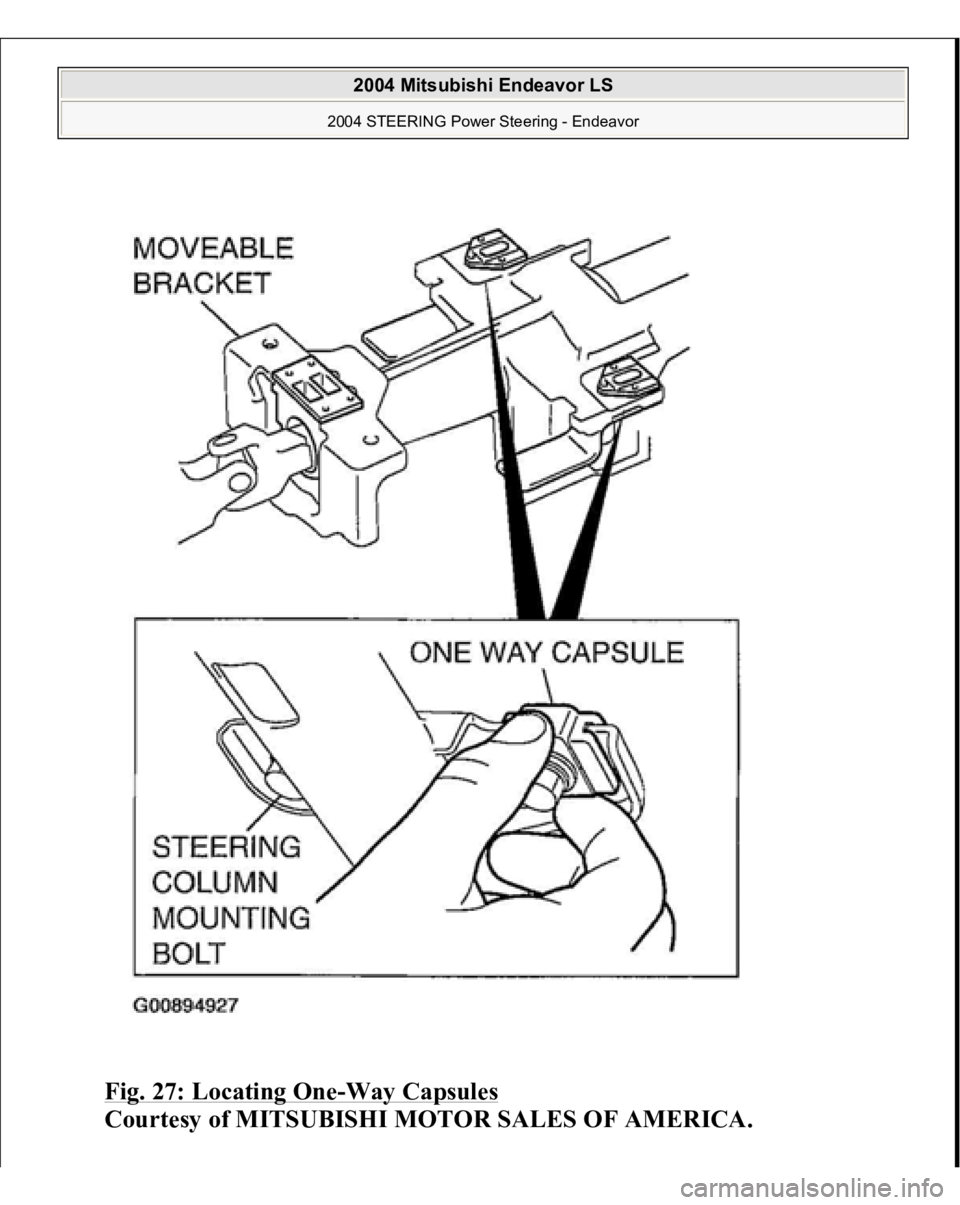
4. Hold the one-way capsules as shown in illustration, and then try to rock them.
If there is a slack in either of the capsules, replace the steering column shaft
assembly.
CAUTION:
1. Be careful that nothing is pinched between
the one-way capsules and the body.
2. On completion, do not release the tilt lever
until the steering column has been installed.
2004 Mitsubishi Endeavor LS
2004 STEERING Power Steering - Endeavor
Page 2865 of 3870
Fig. 27: Locating One
-Way Capsules
Courtesy of MITSUBISHI MOTOR SALES OF AMERICA.
2004 Mitsubishi Endeavor LS
2004 STEERING Power Steering - Endeavor
Page 2866 of 3870
5. Loosen the two lower steering column mounting bolts by two turns.
6. If there is any sign of looseness when the moveable bracket is moved back and
forth by hand, replace the steering column shaft assembly with a new one.
7. If no problem is found during the inspection, tighten the steering column
mounting bolts to the specified torque.
Tightening torque: 12 +/- 2 N.m (102 +/- 22 in-lb) STEERING WHEEL REMOVAL AND INSTALLATION Post-installation Operation
Checking Steering Wheel Position with Wheels Straight Ahead
WARNING:
Before removing the steering wheel and air bag
module assembly, refer to AIR BAG SAFETY PRECAUTIONS
and DRIVER
-SIDE AIR BAG
MODULE & CLOCKSPRING
or PASSENGER
-
SIDE AIR BAG MODULE
.
When removing and installing the steering
wheel, do not let it bump against the air bag
module.
2004 Mitsubishi Endeavor LS
2004 STEERING Power Steering - Endeavor
Page 2867 of 3870
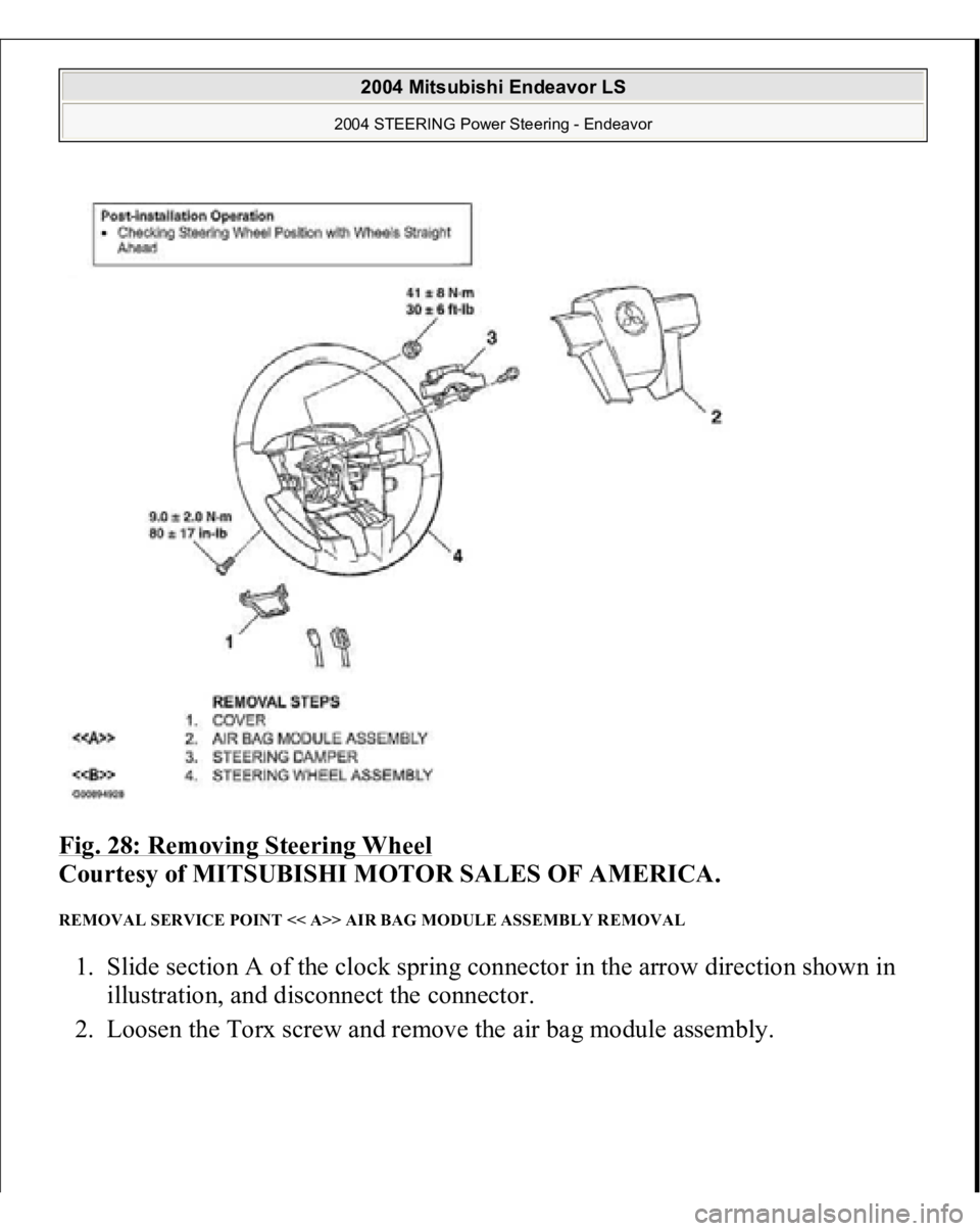
Fig. 28: Removing Steering Wheel
Courtesy of MITSUBISHI MOTOR SALES OF AMERICA.
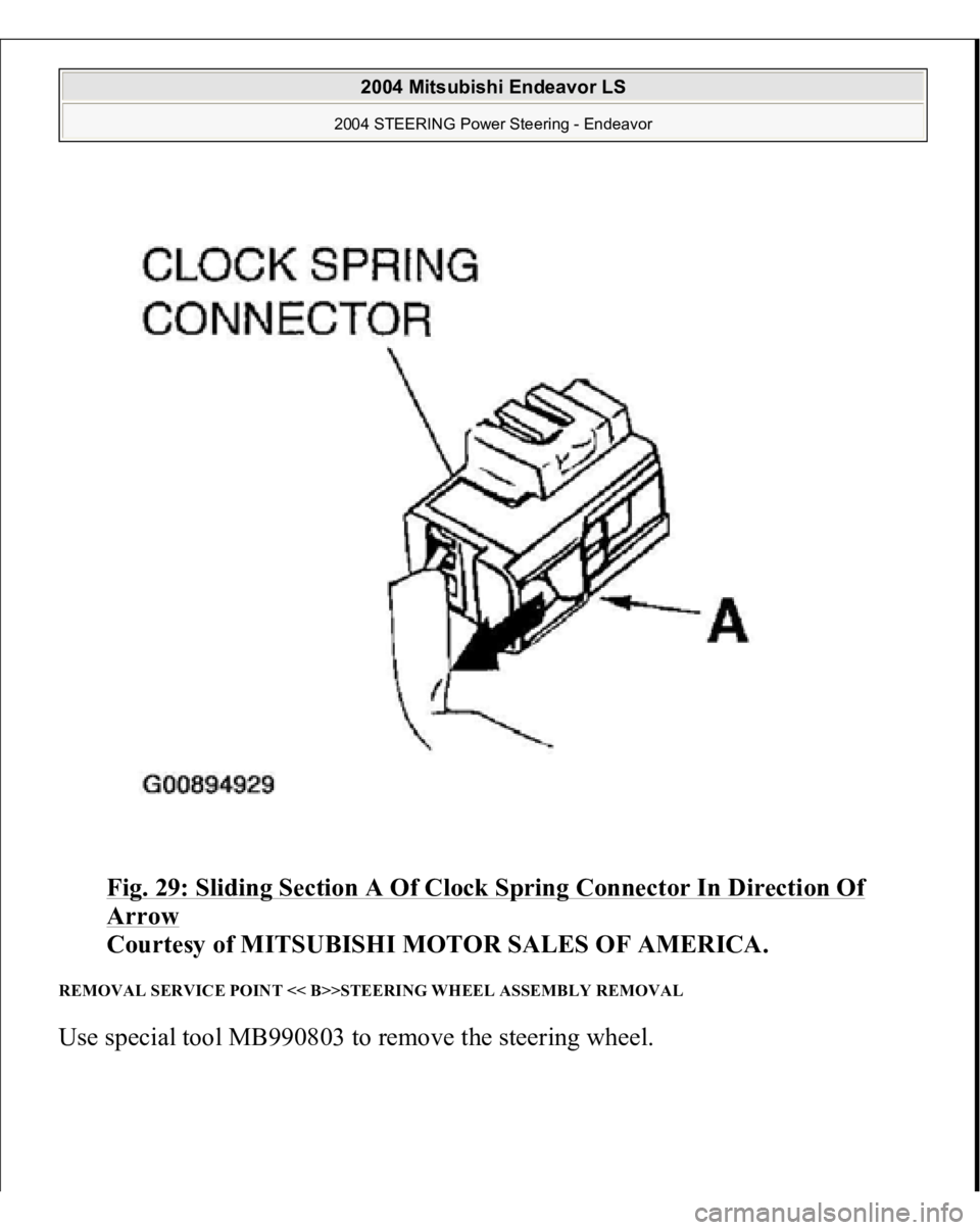
REMOVAL SERVICE POINT << A>> AIR BAG MODULE ASSEMBLY REMOVAL 1. Slide section A of the clock spring connector in the arrow direction shown in
illustration, and disconnect the connector.
2. Loosen the Torx screw and remove the air ba
g module assembl
y.
2004 Mitsubishi Endeavor LS
2004 STEERING Power Steering - Endeavor
Page 2868 of 3870
Fig. 29: Sliding Section A Of Clock Spring Connector In Direction Of Arrow
Courtesy of MITSUBISHI MOTOR SALES OF AMERICA.
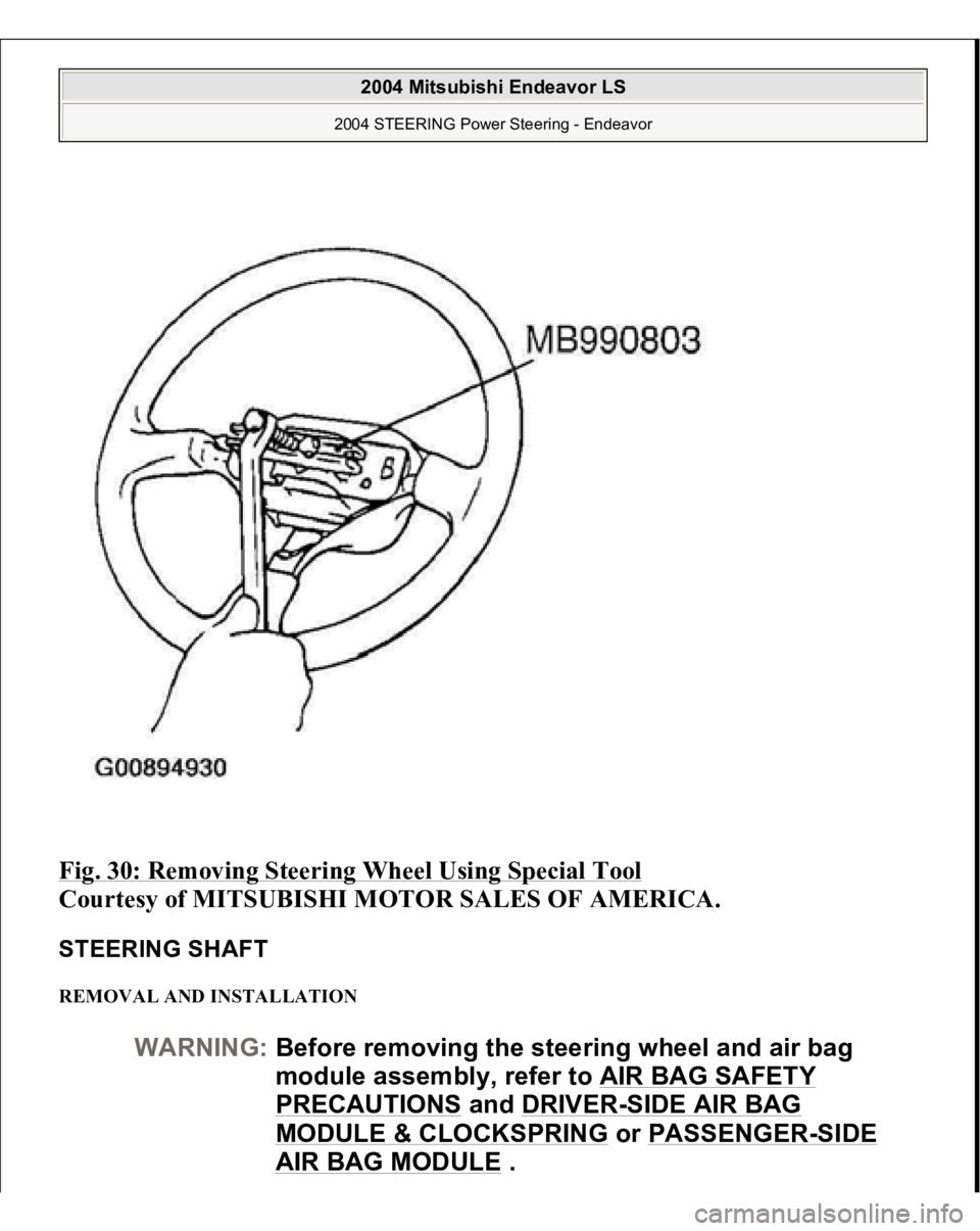
REMOVAL SERVICE POINT << B>>STEERING WHEEL ASSEMBLY REMOVAL Use s
pecial tool MB990803 to remove the steerin
g wheel.
2004 Mitsubishi Endeavor LS
2004 STEERING Power Steering - Endeavor
Page 2869 of 3870
Fig. 30: Removing Steering Wheel Using Special Tool
Courtesy of MITSUBISHI MOTOR SALES OF AMERICA.
STEERING SHAFT REMOVAL AND INSTALLATION
WARNING:Before removing the steering wheel and air bag
module assembly, refer to AIR BAG SAFETY
PRECAUTIONS
and DRIVER
-SIDE AIR BAG
MODULE & CLOCKSPRING
or PASSENGER
-SIDE
AIR BAG MODULE
.
2004 Mitsubishi Endeavor LS
2004 STEERING Power Steering - Endeavor
Page 2870 of 3870
Pre-removal Operation
Front Scuff Plate and Cowl Side Trim Removal (Refer to TRIMS
.)
Steering Wheel and Air bag Module Assembly Removal (Refer to
STEERING WHEEL
.)
Instrument Panel Side Cover and Under Cover Removal (Refer to
INSTRUMENT PANEL ASSEMBLY
.)
Floor Console Side Cover (LH) Removal (Refer to FLOOR CONSOLE ASSEMBLY
.)
Front Floor Carpet Removal
Post-installation Operation Front Floor Console Installation Floor Console Side Cover (LH) Installation (Refer to FLOOR CONSOLE ASSEMBLY
.)
Instrument Panel Side Cover and Under Cover Removal (Refer to
INSTRUMENT PANEL ASSEMBLY
.)
Steering Wheel and Air bag Module Assembly Installation (Refer to
STEERING WHEEL
.)
Front Scuff Plate and Cowl Side Trim Removal (Refer to TRIMS
.)
Steering Wheel Sensor Calibration < Vehicles with ASC> (Refer to
STEERING WHEEL SENSOR CALIBRATION
.)
CAUTION: On vehicles with ASC, always carry out steering
wheel sensor calibration after the steering shaft has
been installed (Refer to STEERING WHEEL SENSOR
CALIBRATION
). This is necessary because the
TCL/ASC-ECU should update the steering neutral
point.
2004 Mitsubishi Endeavor LS
2004 STEERING Power Steering - Endeavor
Trending: Wheel hub assembly, sunroof jam, oil level, Lift, p0340, sunroof, ABS
