MITSUBISHI ENDEAVOR 2004 Service Repair Manual
ENDEAVOR 2004
MITSUBISHI
MITSUBISHI
https://www.carmanualsonline.info/img/19/57105/w960_57105-0.png
MITSUBISHI ENDEAVOR 2004 Service Repair Manual
Trending: Fuel pump relay, CD changer, fog light, power steering fluid, coolant level, Filter, clock
Page 2901 of 3870
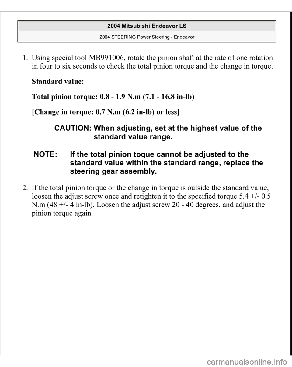
1. Using special tool MB991006, rotate the pinion shaft at the rate of one rotation
in four to six seconds to check the total pinion torque and the change in torque.
Standard value:
Total pinion torque: 0.8 - 1.9 N.m (7.1 - 16.8 in-lb)
[Change in torque: 0.7 N.m (6.2 in-lb) or less]
2. If the total pinion torque or the change in torque is outside the standard value,
loosen the adjust screw once and retighten it to the specified torque 5.4 +/- 0.5
N.m (48 +/- 4 in-lb). Loosen the adjust screw 20 - 40 degrees, and adjust the
pinion torque again.
CAUTION: When adjusting, set at the highest value of the
standard value range.
NOTE: If the total pinion toque cannot be adjusted to the
standard value within the standard range, replace the
steering gear assembly.
2004 Mitsubishi Endeavor LS
2004 STEERING Power Steering - Endeavor
Page 2902 of 3870
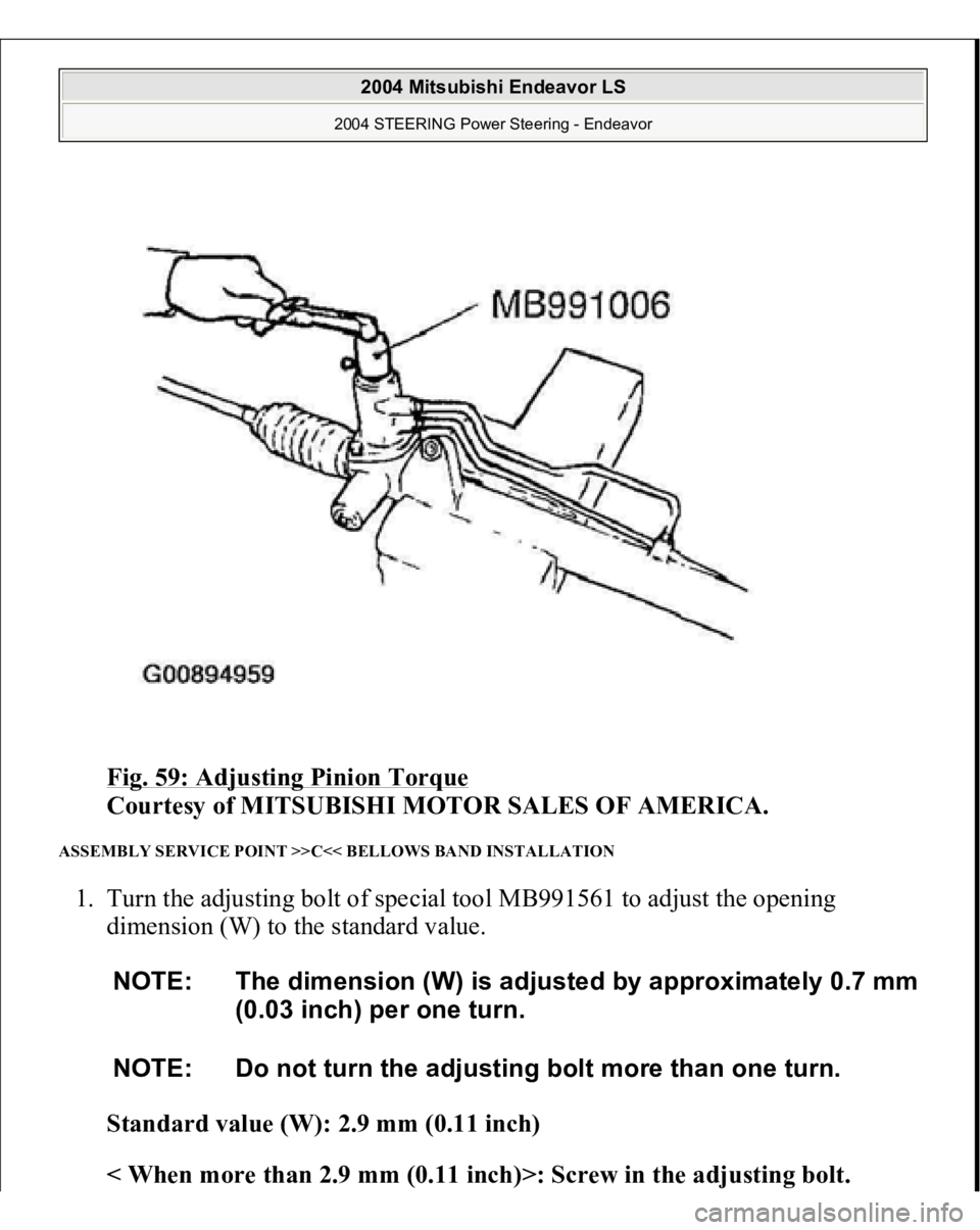
Fig. 59: Adjusting Pinion Torque
Courtesy of MITSUBISHI MOTOR SALES OF AMERICA.
ASSEMBLY SERVICE POINT >>C<< BELLOWS BAND INSTALLATION 1. Turn the adjusting bolt of special tool MB991561 to adjust the opening
dimension (W) to the standard value.
Standard value (W): 2.9 mm (0.11 inch)
< When more than 2.9 mm (0.11 inch)>: Screw in the adjusting bolt.
NOTE: The dimension (W) is adjusted by approximately 0.7 mm
(0.03 inch) per one turn.
NOTE: Do not turn the adjusting bolt more than one turn.
2004 Mitsubishi Endeavor LS
2004 STEERING Power Steering - Endeavor
Page 2903 of 3870
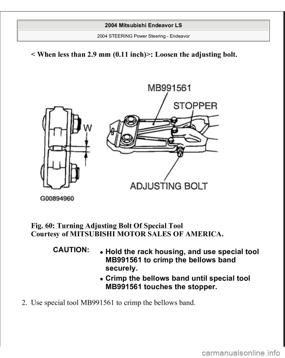
< When less than 2.9 mm (0.11 inch)>: Loosen the ad
justing bolt
.
Fig. 60: Turning Adjusting Bolt Of Special Tool
Courtesy of MITSUBISHI MOTOR SALES OF AMERICA.
2. Use s
pecial tool MB991561 to crim
p the bellows ban
d.
CAUTION:
Hold the rack housing, and use special tool
MB991561 to crimp the bellows band
securely. Crimp the bellows band until special tool
MB991561 touches the stopper.
2004 Mitsubishi Endeavor LS
2004 STEERING Power Steering - Endeavor
Page 2904 of 3870
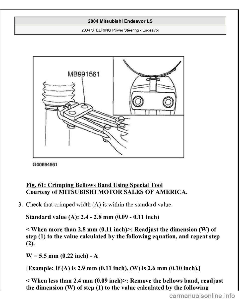
Fig. 61: Crimping Bellows Band Using Special Tool
Courtesy of MITSUBISHI MOTOR SALES OF AMERICA.
3. Check that crimped width (A) is within the standard value.
Standard value (A): 2.4 - 2.8 mm (0.09 - 0.11 inch)
< When more than 2.8 mm (0.11 inch)>: Readjust the dimension (W) of
step (1) to the value calculated by the following equation, and repeat step
(2).
W = 5.5 mm (0.22 inch) - A
[Example: If (A) is 2.9 mm (0.11 inch), (W) is 2.6 mm (0.10 inch).]
< When less than 2.4 mm (0.09 inch)>: Remove the bellows band, readjust
the dimension
(W) of ste
p (1) to the value calculated b
y the followin
g
2004 Mitsubishi Endeavor LS
2004 STEERING Power Steering - Endeavor
Page 2905 of 3870
equation, and use a new bellows band to repeat steps (2) to (3)
.
W = 5.5 mm (0.22 inch) - A
[Example: if (A) is 2.3 mm (0.09 inch), (W) is 3.2 mm (0.13 inch).]
Fig. 62: Checking Crimped Width (A)
Courtesy of MITSUBISHI MOTOR SALES OF AMERICA.
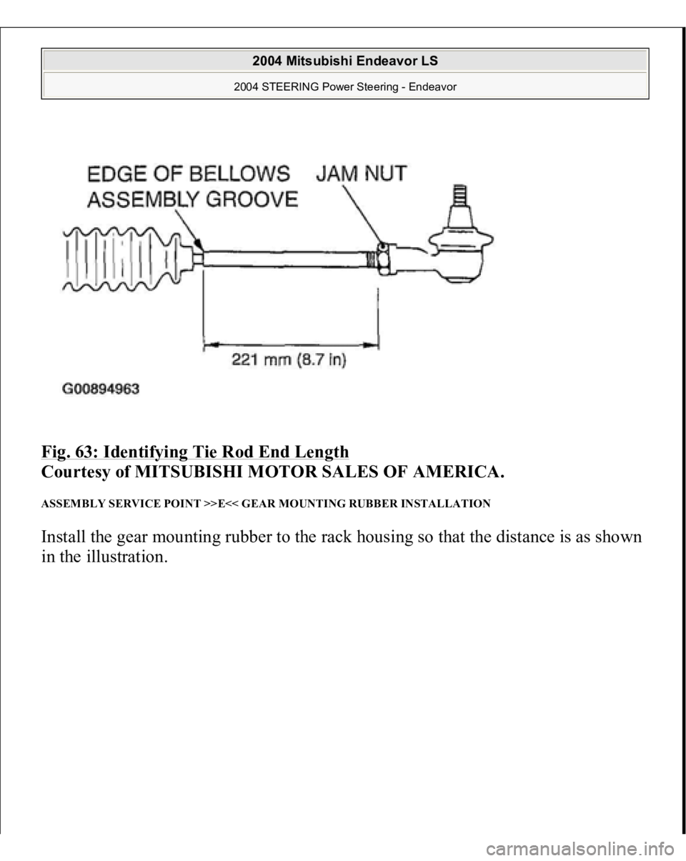
ASSEMBLY SERVICE POINT >>D<< TIE ROD END/JAM NUT INSTALLATION Screw in the tie rod end to achieve the right and left length as shown in illustration.
Lock with the jam nut. NOTE: The locking nuts must be tightened securely only after the
steering gear is installed and toe is adjusted.
2004 Mitsubishi Endeavor LS
2004 STEERING Power Steering - Endeavor
Page 2906 of 3870
Fig. 63: Identifying Tie Rod End Length
Courtesy of MITSUBISHI MOTOR SALES OF AMERICA.
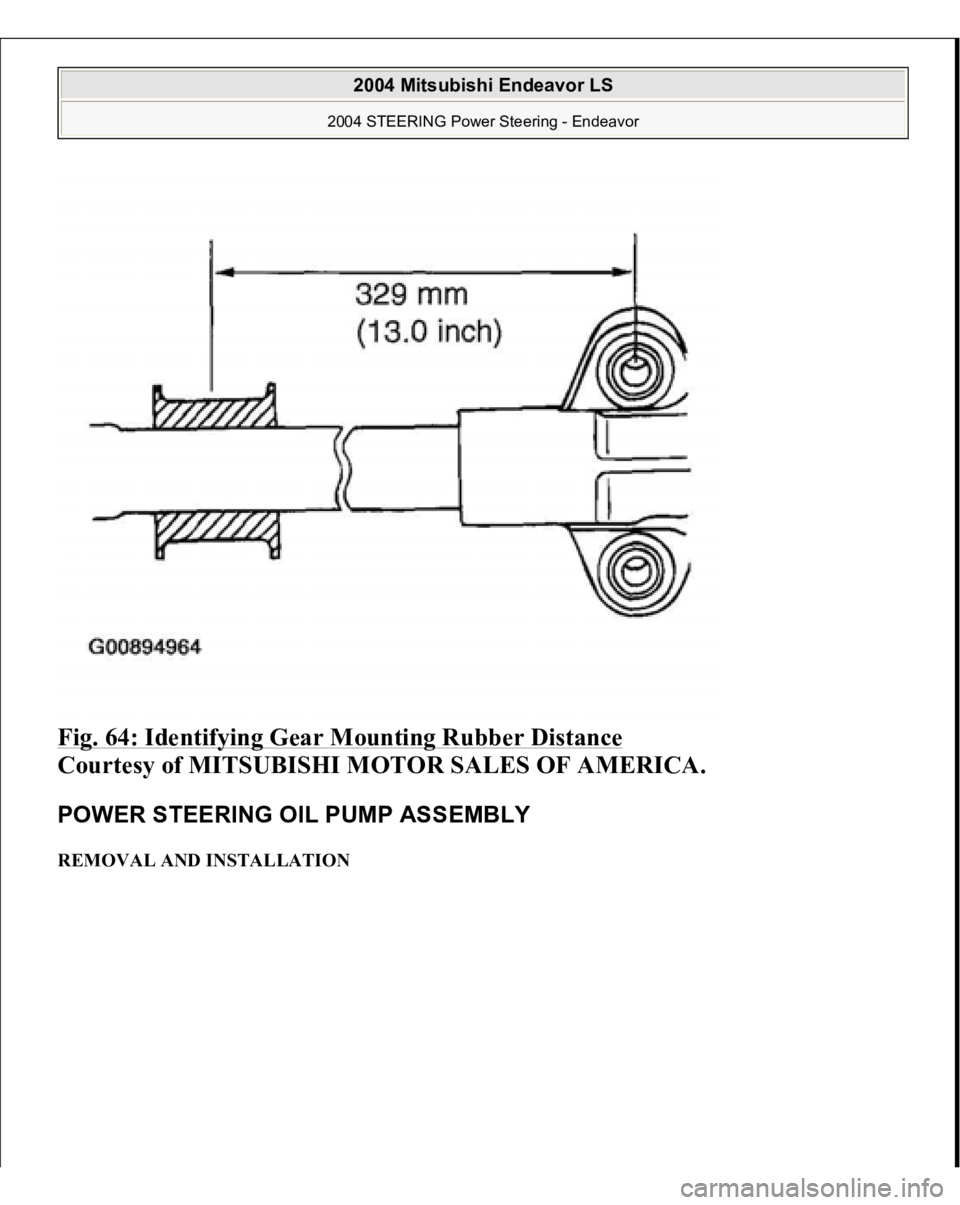
ASSEMBLY SERVICE POINT >>E<< GEAR MOUNTING RUBBER INSTALLATION Install the gear mounting rubber to the rack housing so that the distance is as shown
in the illustration.
2004 Mitsubishi Endeavor LS
2004 STEERING Power Steering - Endeavor
Page 2907 of 3870
Fig. 64: Identifying Gear Mounting Rubber Distance
Courtesy of MITSUBISHI MOTOR SALES OF AMERICA.
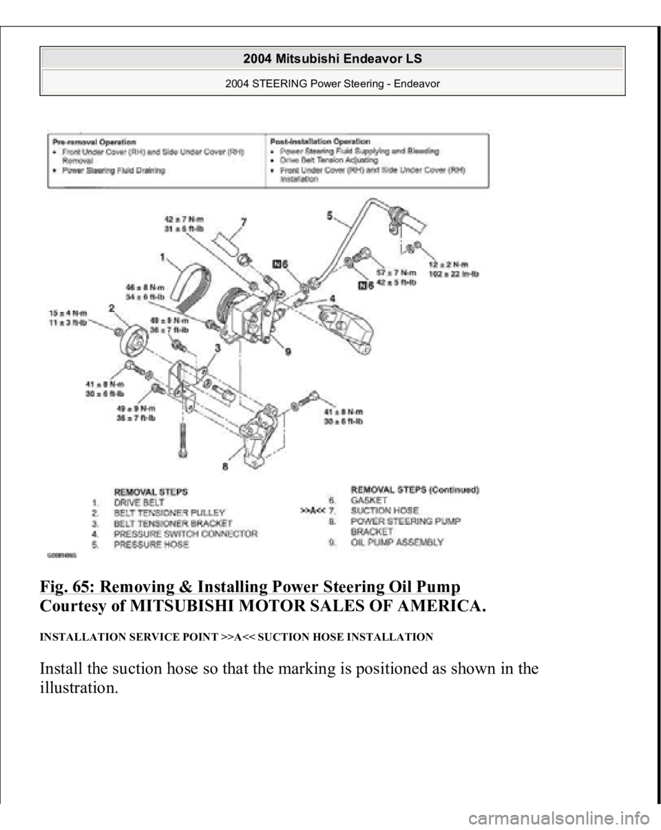
POWER STEERING OIL PUMP ASSEMBLY REMOVAL AND INSTALLATION
2004 Mitsubishi Endeavor LS
2004 STEERING Power Steering - Endeavor
Page 2908 of 3870
Fig. 65: Removing & Installing Power Steering Oil Pump
Courtesy of MITSUBISHI MOTOR SALES OF AMERICA.
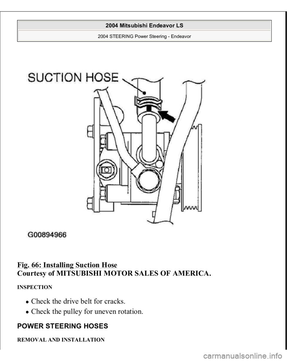
INSTALLATION SERVICE POINT >>A<< SUCTION HOSE INSTALLATION Install the suction hose so that the marking is positioned as shown in the
illustration.
2004 Mitsubishi Endeavor LS
2004 STEERING Power Steering - Endeavor
Page 2909 of 3870
Fig. 66: Installing Suction Hose
Courtesy of MITSUBISHI MOTOR SALES OF AMERICA.
INSPECTION
Check the drive belt for cracks. Check the pulley for uneven rotation.
POWER STEERING HOSES REMOVAL AND INSTALLATION
2004 Mitsubishi Endeavor LS
2004 STEERING Power Steering - Endeavor
Page 2910 of 3870
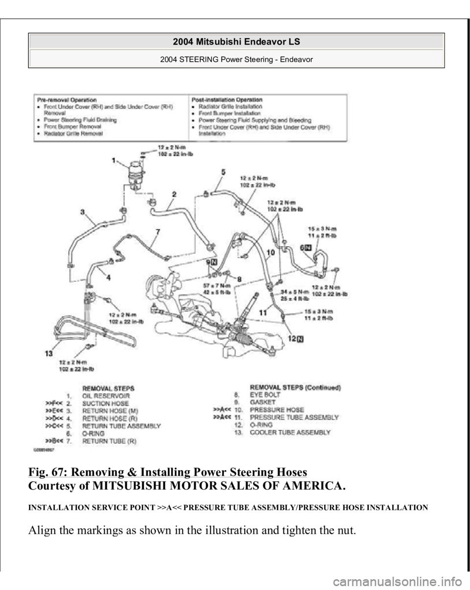
Fig. 67: Removing & Installing Power Steering Hoses
Courtesy of MITSUBISHI MOTOR SALES OF AMERICA.
INSTALLATION SERVICE POINT >>A<< PRESSURE TUBE ASSEMBLY/PRESSURE HOSE INSTALLATION Ali
gn the markin
gs as shown in the illustration an
d tighten the nut.
2004 Mitsubishi Endeavor LS
2004 STEERING Power Steering - Endeavor
Trending: Hvac, bolt tightening order, service indicator, power steering, jump cable, oil temperature, door lock
![MITSUBISHI ENDEAVOR 2004 Service Repair Manual equation, and use a new bellows band to repeat steps (2) to (3)
.
W = 5.5 mm (0.22 inch) - A
[Example: if (A) is 2.3 mm (0.09 inch), (W) is 3.2 mm (0.13 inch).]
Fig. 62: Checking Crimped Width ( MITSUBISHI ENDEAVOR 2004 Service Repair Manual equation, and use a new bellows band to repeat steps (2) to (3)
.
W = 5.5 mm (0.22 inch) - A
[Example: if (A) is 2.3 mm (0.09 inch), (W) is 3.2 mm (0.13 inch).]
Fig. 62: Checking Crimped Width (](/img/19/57105/w960_57105-2904.png)
