MITSUBISHI GALANT 1989 Service Repair Manual
Manufacturer: MITSUBISHI, Model Year: 1989, Model line: GALANT, Model: MITSUBISHI GALANT 1989Pages: 1273, PDF Size: 37.62 MB
Page 231 of 1273
FUEL SYSTEM
:Federab
:California>
Ea
SENSOR INSPECTION
Caution
1. Before checking, warm up the engine until engine
coolant temperature reaches 85 to 95°C (185 to 205°F).
2. Use an accurate digital voltmeter.
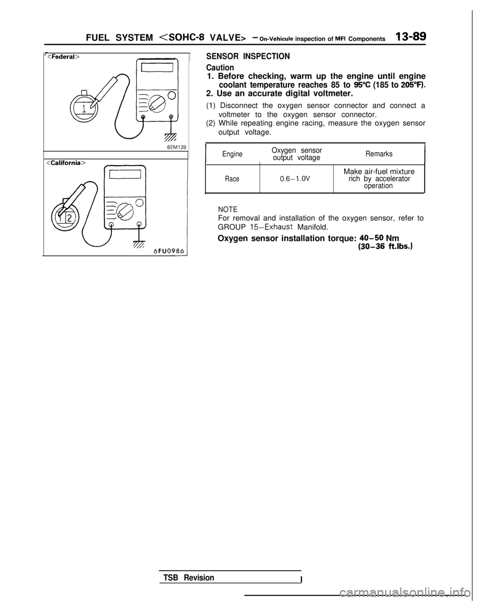
(1) Disconnect the oxygen sensor connector and connect a voltmeter to the oxygen sensor connector.
(2) While repeating engine racing, measure the oxygen sensor
output voltage.
,
IEngineOxygen sensoroutput voltageRemarks
Race0.6-l .OVMake air-fuel mixturerich by acceleratoroperation
NOTE
For removal and installation of the oxygen sensor, refer to
GROUP
15-Exhaust Manifold.
Oxygen sensor installation torque:
40-50 Nm
(30-36 ft.lbs.1
TSB Revision I
Page 232 of 1273
13-90 FUEL SYSTEM
INJECTORS
Fuel
Connector
Solenoid coil
Plunger
Needle valve -----I
InjectionFilter6FUO514
M13rrAA
Multiport
fuel injection relay
No.1 &j No.2& No.3& No,4+
tI
lFUO642
Engine control module connector
CJ=JW=U-I
0 1 LO636
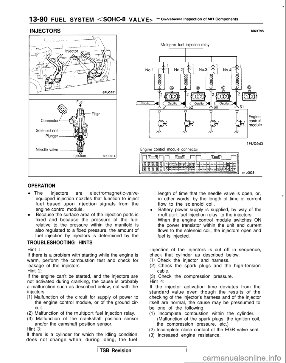
OPERATION
l The
injectorsare electromagnetic-valve-
equipped injection nozzles that function to inject
fuel based upon injection signals from the
engine control module.
lBecause the surface area of the injection ports is
fixed and because the pressure of the fuel
relative to the pressure within the manifold is
also regulated to a fixed pressure, the amount of
fuel injection by injectors is determined by the
TROUBLESHOOTING HINTS
Hint 1:
If there is a problem with starting while the engine is
warm, perform the combustion test and check for leakage of the injectors.
Hint
2,
If the engine can’t be started, and the injectors are
not activated during cranking, the cause is probably
a malfunction such as described below, not with the
injectors.
(I) Malfunction of the circuit for supply of power to the engine control module, or of the ground cir-
cuit.
(2) Malfunction of the multiport fuel injection relay.
(3) Malfunction of the crankshaft position sensor and/or the camshaft position sensor.
Hint
3.
If there is a cylinder for which the idling condition
does not change when, during idling, the fuel length of time that the needle valve is open, or,
in other words, by the length of time of current
~-
flow to the solenoid coil.
lBattery power supply is supplied, by way of the
multiport fuel injection relay, to the injectors.
When the engine control module switches ON
the power transistor within the unit and current
flows to the solenoid coil, the injectors open and
fuel is injected.
injection of the injectors is cut off in sequence,
check that cylinder as described below.
(1) Check the injector and harness.
(2) Check the spark plugs and the high-tension
cable.
(3) Check the compression pressure. Hint 4:
If the injector activation time deviates from the
standard value even though the results of the
checking of the injector’s harness and of the injector itself are normal, the cause may be pressumed to
be one of the following,
(1) Incomplete combustion within the cylinder. (Malfunction of the spark plugs, the ignition coil,
the compression pressure, etc.)
(2) Incomplete close contact of the EGR valve seat.
(3) Increased engine resistance.
1 TSB RevisionI
Page 233 of 1273
FUEL SYSTEM
Inspection of MFI Components13-91
INSPECTION
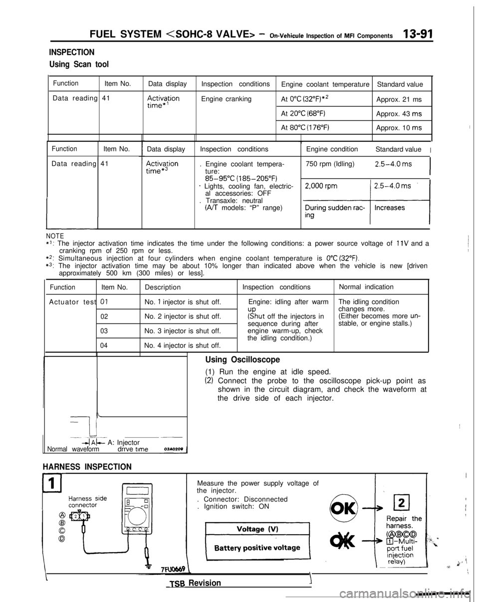
Using Scan tool
FunctionItem No. Data display
Data reading 41
III~~~ion
Inspection conditions Engine coolant temperature Standard value
Engine cranking At
0°C (3~2°F)“~Approx. 21 ms
At
20°C (68°F)Approx. 43 ms
At
80°C (176°F)Approx. 10 ms
FunctionItem No.
Data reading 41
L
Data display
Ac&a$ion
Inspection conditions
. Engine coolant tempera- ture:
85-95°C (185-205°F)* Lights, cooling fan, electric-al accessories: OFF
. Transaxle: neutral
(A/T models: “P” range) Engine condition
Standard value
I
750 rpm (Idling)2.5-4.0 ms
I
NOTE*I: The injector activation time indicates the time under the following con\
ditions: a power source voltage of 11V and a
cranking rpm of 250 rpm or less.
**: Simultaneous injection at four cylinders when engine coolant temperatur\
e is 0°C (32°F).*3: The injector activation time may be about 10% longer than indicated abo\
ve when the vehicle is new [driven approximately 500 km (300 miles) or less].
FunctionItem No.
Actuator test
01
02
03
04
Description
No.
1 injector is shut off.
No. 2 injector is shut off.
No. 3 injector is shut off.
No. 4 injector is shut off. Inspection conditions
Normal indication
Engine: idling after warm The idling condition
changes more.
r”sput off the injectors in(Either becomes more un-sequence during after stable, or engine stalls.)
engine warm-up, check
the idling condition.)
-
I i-. --.-~-db$- A: Injector~__
Normal waveformdrrve time
HARNESS INSPECTION
1
P
Using Oscilloscope
(1) Run the engine at idle speed.
(2) Connect the probe to the oscilloscope pick-up point as
shown in the circuit diagram, and check the waveform at
the drive side of each injector.
Measure the power supply voltage of
the injector.
. Connector: Disconnected. Ignition switch: ON
TSB Revision
I
I
4
i1
k ji,v,11
\
YIY’.
Page 234 of 1273
13-92 FUEL SYSTEM
- On-Vehicule Inspection of MFI Components
21Harnesssideconnector
g *’
gr
module harnessside connector
-rlFUO643
‘/6FUO870
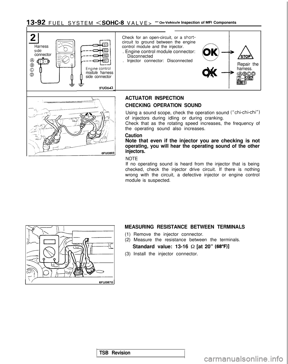
Check for an open-circuit, or a short-circuit to ground between the engine
control module and the injector.
. Engine control module connector:
Disconnected. Injector connector: Disconnected
:
ASTOP
Repair theharness.
ACTUATOR INSPECTION
CHECKING OPERATION SOUND
Using a sound scope, check the operation sound (“chi-chi-chi”)
of injectors during idling or during cranking.
Check that as the rotating speed increases, the frequency of
the operating sound also increases.
Caution
Note that even if the injector you are checking is not
operating, you will hear the operating sound of the other
injectors.
NOTE
If no operating sound is heard from the injector that is being
checked, check the injector drive circuit. If there is nothing
wrong with the circuit, a defective injector or engine control module is suspected.
MEASURING RESISTANCE BETWEEN TERMINALS
(1) Remove the injector connector.
(2) Measure the resistance between the terminals.
Standard value: 13-16
Q [at 20” (68”F)]
(3) Install the injector connector.
TSB Revision
Page 235 of 1273
FUEL SYSTEM
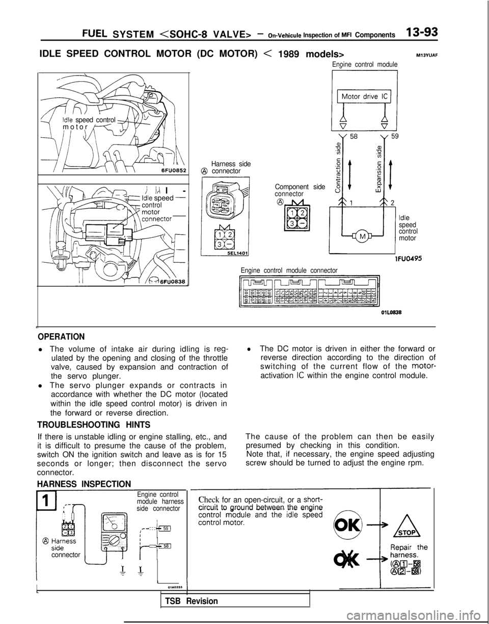
IDLE SPEED CONTROL MOTOR (DC MOTOR)
Idle speed control9-/
motor
/---T-,I \
6FUO852
i id l
-
Idle speed -control
r1 /&46~U0838
Harness side@ connector
< 1989 models>
Enoine control module
M13YUAF
Component sideconnector
!
a,Yg
z.-t;Fs 8
B
12
d
Idle
speed
control
Mmotor
lFUO495
Engine control module connector
1
OPERATION
l The volume of intake air during idling is reg-
ulated by the opening and closing of the throttle
valve, caused by expansion and contraction of
the servo plunger.
l The servo plunger expands or contracts in accordance with whether the DC motor (located
within the idle speed control motor) is driven in
the forward or reverse direction.
lThe DC motor is driven in either the forward or reverse direction according to the direction of
switching of the current flow of the motor-
activation
IC within the engine control module.
TROUBLESHOOTING HINTS
If there is unstable idling or engine stalling, etc., and
it is difficult to presume the cause of the problem,
switch ON the ignition switch and leave as is for 15
seconds or longer; then disconnect the servo
connector.
HARNESS INSPECTION
The cause of the problem can then be easily presumed by checking in this condition.Note that, if necessary, the engine speed adjusting
screw should be turned to adjust the engine rpm.
Iconnector
Engine control
module harness
side connector
IIrIsEI
r- r-
II01.03,~I
TSB Revision
Check for an open-circuit, or a short-circuit to ground between the engine
Page 236 of 1273
13-94 FUEL SYSTEM
1
Idle speed control
motor connector
Idle speed control
motor connector6FUO750
6FUO9&
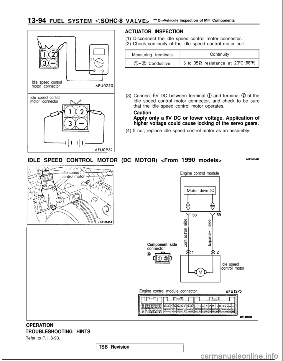
ACTUATOR INSPECTION
(1) Disconnect the idle speed control motor connector.
(2) Check continuity of the idle speed control motor coil.
Measuring terminals Continuity
0-0 Conductive
5 to 359 resistance at 20°C (68°F)
(3) Connect 6V DC between terminal @I and terminal @ of the
idle speed control motor connector, and check to be sure
that the idle speed control motor operates.
Caution
Apply only a 6V DC or lower voltage. Application of
higher voltage could cause locking of the servo gears.
(4) If not, replace idle speed control motor as an assembly.
IDLE SPEED CONTROL MOTOR (DC MOTOR)
Component sideconnector
@
43m00
Engine control module
77V s
.-:
z'Zc
EE
sI2
21<\2
Idle speedcontrol motor
MlOYUAG
Engine control module connector
6FU1275
OPERATION
TROUBLESHOOTING HINTS
Refer to P. ? 3-93.
TSB Revision
Page 237 of 1273
FUEL SYSTEM
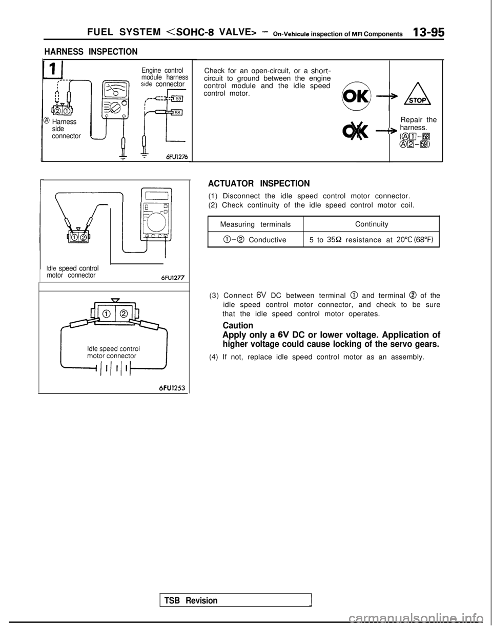
HARNESS INSPECTION
3 Harness
side
connector
Engine control
module harness
sde connector
+6FU1276
I I
Lit02
Idle speed controlmotor connector6FU1277
6FU1253
Check for an open-circuit, or a short-circuit to ground between the engine
control module and the idle speed
control motor.
Repair the
-+ harness.
OZGII-8@m-8)
TSB Revision
ACTUATOR INSPECTION
(1) Disconnect the idle speed control motor connector.
(2) Check continuity of the idle speed control motor coil.Measuring terminals Continuity
0-0 Conductive
5 to 3552 resistance at 20°C (68°F)
(3) Connect 6V
DC between terminal @
and terminal @ of the
idle speed control motor connector, and check to be sure
that the idle speed control motor operates.
Caution
Apply only a 6V
DC or lower voltage. Application of
higher voltage could cause locking of the servo gears.
(4) If not, replace idle speed control motor as an assembly.
Page 238 of 1273
13-96 FUEL SYSTEM
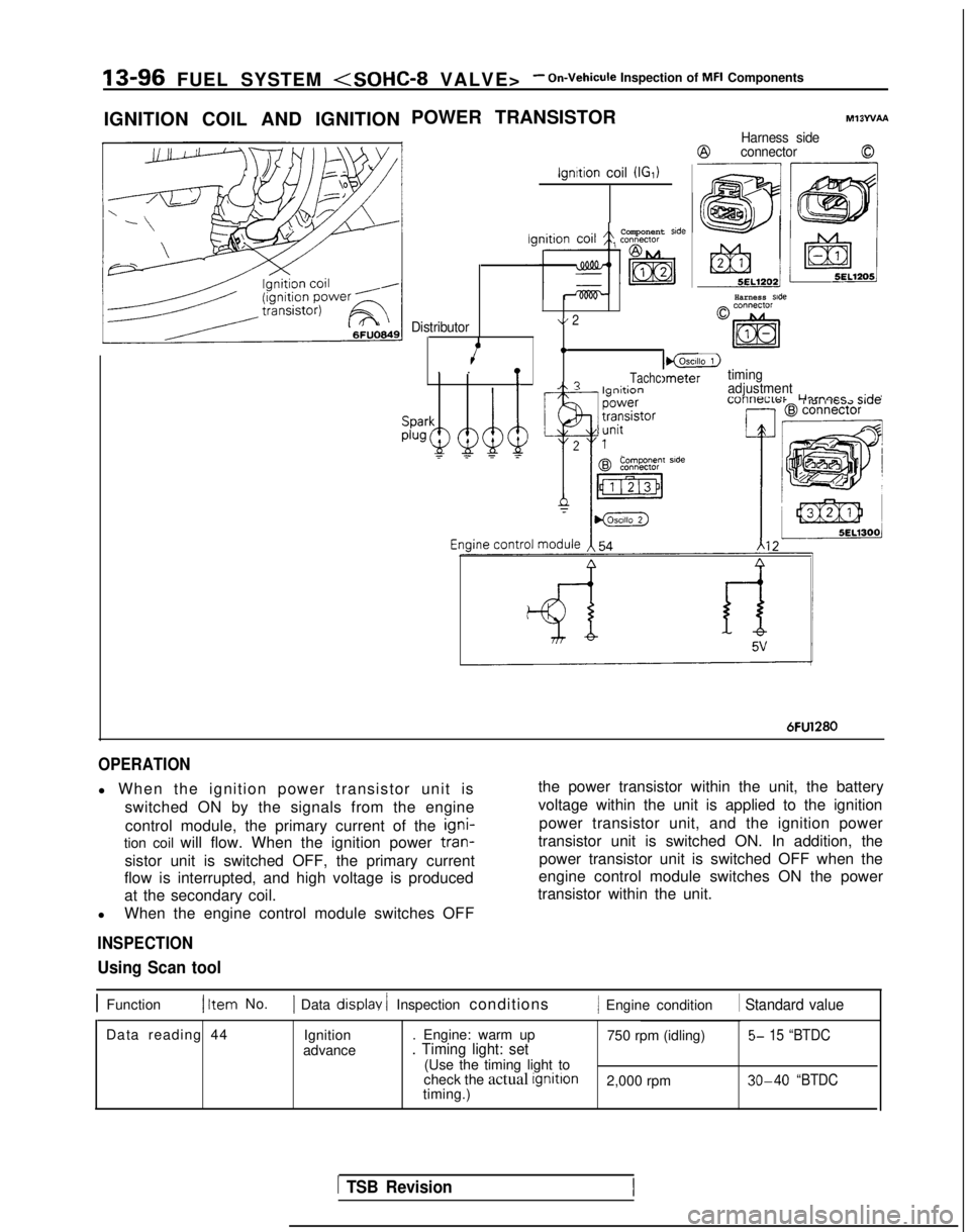
IGNITION COIL AND IGNITION POWER TRANSISTOR
ignition coil (IGI)
Ml3WAA
Harness side
@connector0
Harness side
Component side
Distributor\/ 2
4.I_lgnltion. .!
I@LZ)
TachcImetertimingA? I--:*:^^adjustment-_
Lllrnacr
r;rlnI 101 i IG.72 Jl”F
Componenr side
6FU1280
OPERATION
l When the ignition power transistor unit is
switched ON by the signals from the engine
control module, the primary current of the igni-
tion coil will flow. When the ignition power tran-
sistor unit is switched OFF, the primary current
flow is interrupted, and high voltage is produced
at the secondary coil.
l When the engine control module switches OFF
INSPECTION
the power transistor within the unit, the battery
voltage within the unit is applied to the ignition
power transistor unit, and the ignition power
transistor unit is switched ON. In addition, the power transistor unit is switched OFF when the
engine control module switches ON the power
transistor within the unit.
Using Scan tool
1 Function1 Item No.1 Data display / Inspection conditions/ Engine condition 1 Standard value
Data reading 44
Ignition
advance . Engine: warm up
750 rpm (idling)5- 15 “BTDC. Timing light: set(Use the timing light to
check the actual ignition
2,000 rpm 30-40 “BTDCtiming.)
1 TSB Revision
Page 239 of 1273
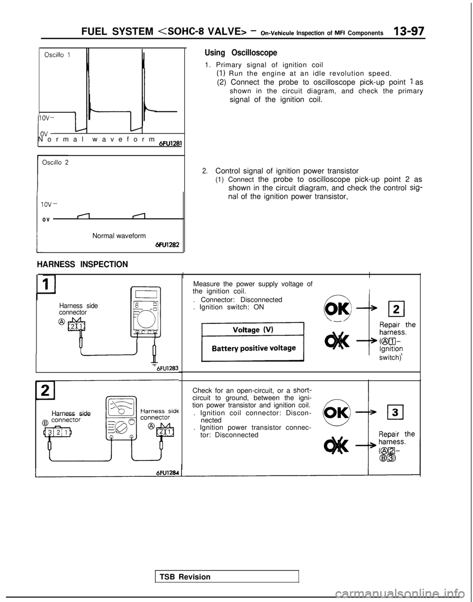
FUEL SYSTEM (SOHC-8 VALVE> -On-Vehicule Inspection of MFI Components13-97
Oscillo 1
If-Normal waveform 6Fu,28,
lOV-
ov
i
nal of the ignition power transistor,
(1
Normal waveform
6Fu1282
Using Oscilloscope
1. Primary signal of ignition coil
(1) Run the engine at an idle revolution speed.
(2) Connect the probe to oscilloscope pick-up point
1 as
shown in the circuit diagram, and check the primary
signal of the ignition coil.
2.Control signal of ignition power transistor
(1) Connect the probe to oscilloscope pick-up point 2 as shown in the circuit diagram, and check the control sig-
Harness side
connector
@
HARNESS INSPECTION
II
I I
I
Measure the power supply voltage of
the ignition coil.
. Connector: Disconnected
. Ignition switch: ON
c--vOK/III2
-‘B-6FU1283
TSB Revision
Harness side
switch)
Check for an open-circuit, or a short-
circuit to ground, between the igni-
tion power transistor and ignition coil.
. Ignition coil connector: Discon- nected
. Ignition power transistor connec-
tor: Disconnected
Page 240 of 1273
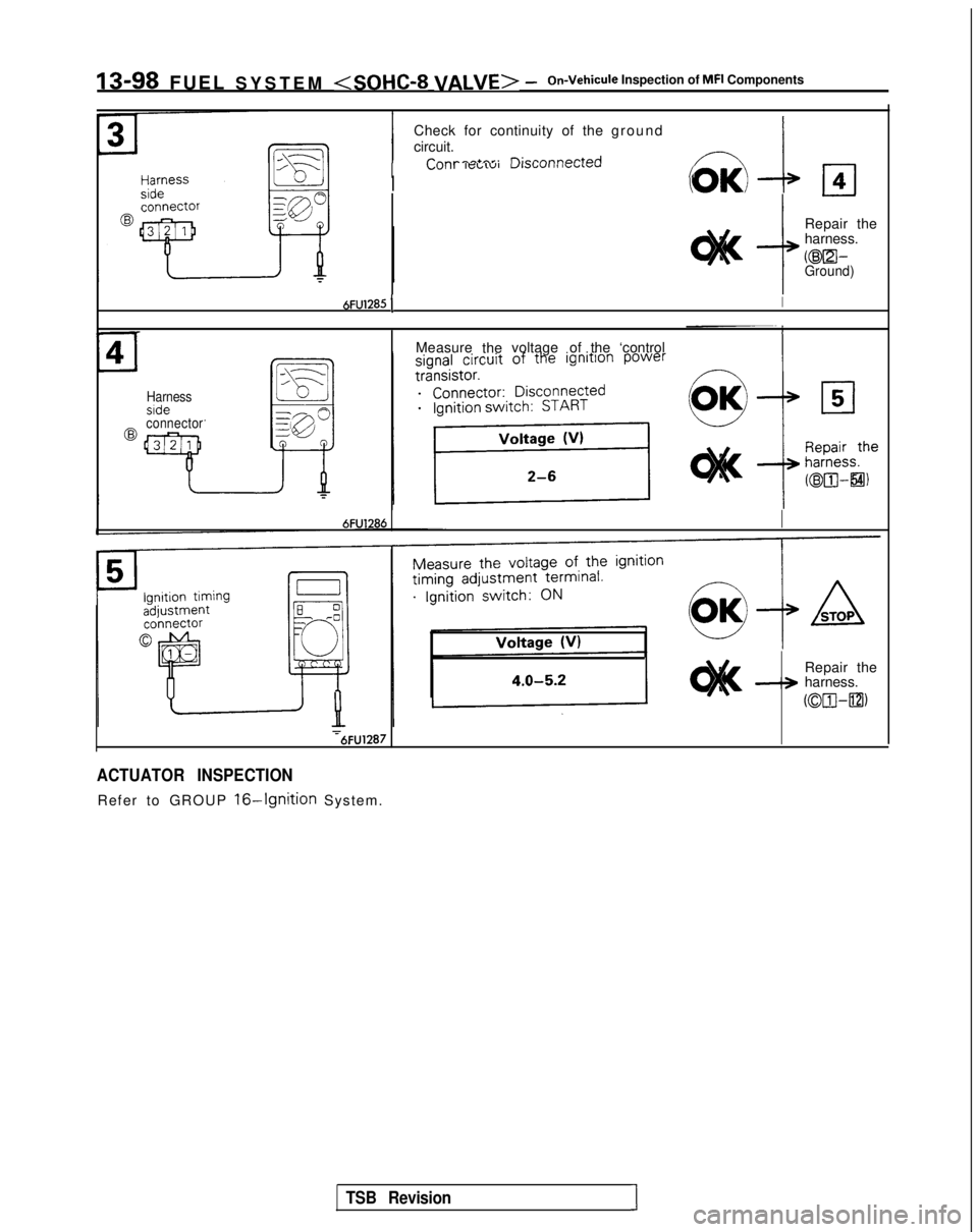
IS-98 FUEL SYSTEM
Check for continuity of the ground
circuit.
IP--^^^+rrr. n;ronnnnr+prjL”,,, ,wdL”IVlJlr”l I4 IbUI””
I
r-l4
I -@Repair the
harness.
@El-Ground)
Harness
6FU1285 1I
Measure
thevoltage
of the ‘control
@connector
6FU1286
Repair the-+ harness.
CtxHm
:6FU1287
ACTUATOR INSPECTION
Refer to GROUP 16-Ignition System.
TSB RevisionI