MITSUBISHI GALANT 1989 Service Repair Manual
Manufacturer: MITSUBISHI, Model Year: 1989, Model line: GALANT, Model: MITSUBISHI GALANT 1989Pages: 1273, PDF Size: 37.62 MB
Page 261 of 1273
Specifications/Special Tools/FUEL SYSTEM
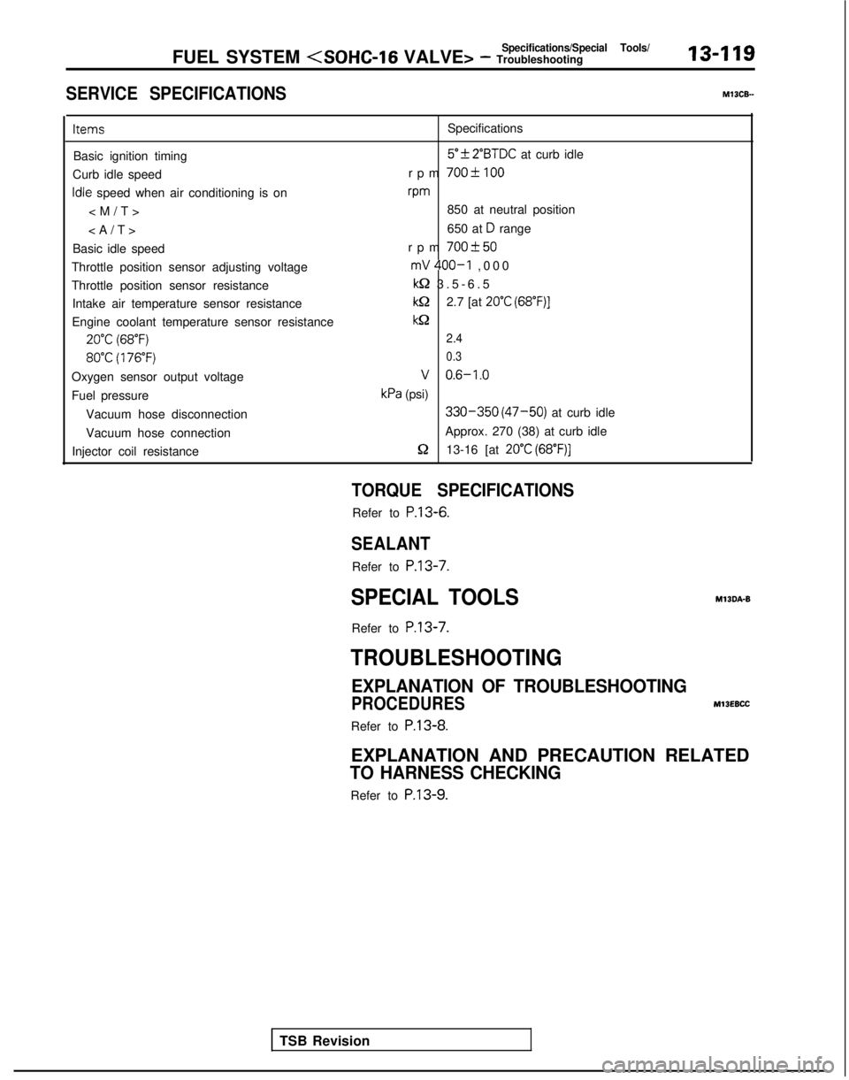
SERVICE SPECIFICATIONS
13-119 MlOCB-
Items
Specifications
Basic ignition timing
5”f 2”BTDC at curb idle
Curb idle speed rpm
700-C 100
Idle speed when air conditioning is onvm
850 at neutral position
650 at
D range
Basic idle speed rpm
700+50
Throttle position sensor adjusting voltagemV 400-I ,00
0
Throttle position sensor resistance
kQ 3.5-6.
5
Intake air temperature sensor resistance
kQ2.7 [at 20°C (68”F)]
Engine coolant temperature sensor resistancekQ
20°C (68°F)2.4
80°C (176°F) 0.3
Oxygen sensor output voltageV 0.6-1.0
Fuel pressurekPa (psi)
Vacuum hose disconnection
330-350 (47-50) at curb idle
Vacuum hose connection Approx. 270 (38) at curb idle
Injector coil resistance
5213-16 [at 20°C (68”F)]
TSB Revision
TORQUE SPECIFICATIONS
Refer to P.13-6.
SEALANT
Refer to
P.13-7.
SPECIAL TOOLS
Refer to
P.13-7.
MlBDA-B
TROUBLESHOOTING
EXPLANATION OF TROUBLESHOOTING
PROCEDURES
MllEBCC
Refer to P.13-8.
EXPLANATION AND PRECAUTION RELATED
TO HARNESS CHECKING
Refer to P.13-9.
Page 262 of 1273
13-120FUEL SYSTEM
CHH;K
ENGINE/MALFUNCTION INDICATOR
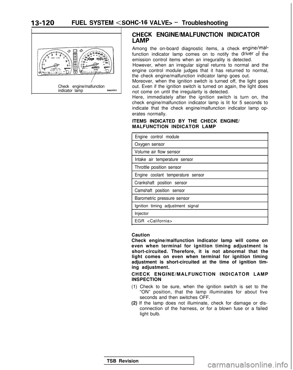
Among the on-board diagnostic items, a check engine/mal-
function indicator lamp comes on to notify the driver
of the
emission control items when an irregurality is detected. However, when an irregular signal returns to normal and the
engine control module judges that it has returned to normal,
the check engine/malfunction indicator lamp goes out. Moreover, when the ignition switch is turned off, the light goes
Check engine/malfunctionout. Even if the ignition switch is turned on again, the light doesindicator lamp68A.0093not come on until the irregularity is detected.
Here, immediately after the ignition switch is turn on, the
check engine/malfunction indicator lamp is lit for 5 seconds to indicate that the check engine/malfunction indicator lamp op-
erates normally.
ITEMS INDICATED BY THE CHECK ENGINE/
MALFUNCTION INDICATOR LAMP
Engine control module
Oxygen sensor
Volume air flow sensor
Intake air temperature sensor
Throttle position sensor
Engine coolant temperature sensor
Crankshaft position sensor Camshaft position sensor
Barometric pressure sensor
Ignition timing adjustment signal
Injector
EGR
Caution
Check engine/malfunction indicator lamp will come on
even when terminal for ignition timing adjustment is short-circuited. Therefore, it is not abnormal that the
light comes on even when terminal for ignition timing
adjustment is short-circuited at the time of ignition tim-
ing adjustment.
CHECK ENGINE/MALFUNCTION INDICATOR LAM
P
INSPECTION
(1) Check to be sure, when the ignition switch is set to the “ON” position, that the lamp illuminates for about five
seconds and then switches OFF.
(2) If the lamp does not illuminate, check for damage or dis- connection of the harness, or for a blown fuse or a failedlight bulb.
TSB Revision
Page 263 of 1273
FUEL SYSTEM
ON-BOARD DIAGNOSTIC
The engine control module monitors the input/out- put signals (some signals at all times and the others
under specified conditions) of the engine control
module.
When it is noticed that an irregularity has continued
for a specified time or longer from when the irregu- lar signal is initially monitored, passing a certain
number, the engine control module judges that an irregularity has occurred, memorizes the diagnostic
trouble code, and outputs the signal to the on-board
diagnostic output terminal.
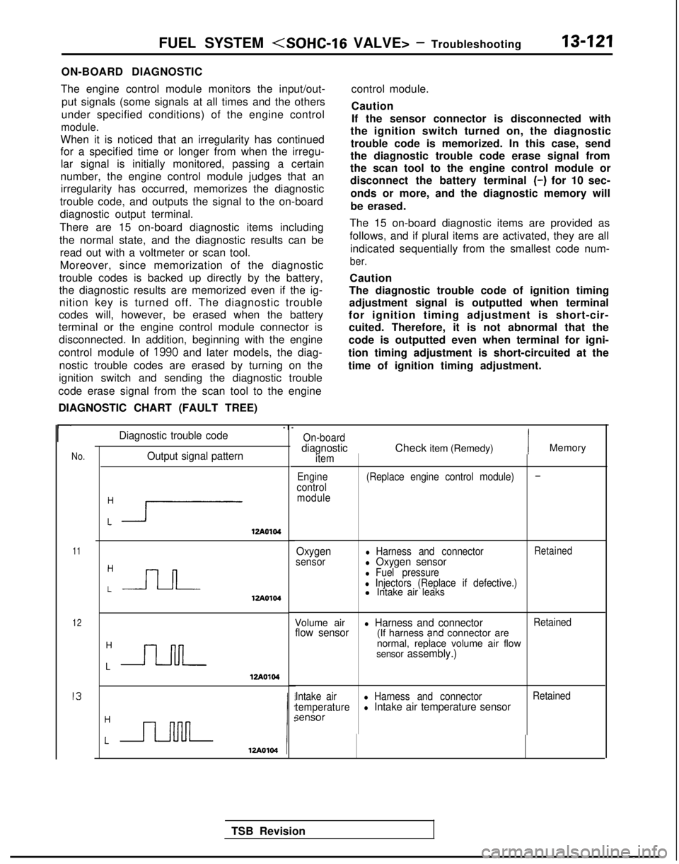
There are 15 on-board diagnostic items including
the normal state, and the diagnostic results can be read out with a voltmeter or scan tool.
Moreover, since memorization of the diagnostic
trouble codes is backed up directly by the battery,
the diagnostic results are memorized even if the ig- nition key is turned off. The diagnostic trouble
codes will, however, be erased when the battery
terminal or the engine control module connector is
disconnected. In addition, beginning with the engine
control module of
1990 and later models, the diag-
nostic trouble codes are erased by turning on the
ignition switch and sending the diagnostic trouble
code erase signal from the scan tool to the engine
DIAGNOSTIC CHART (FAULT TREE) control module.
Caution
If the sensor connector is disconnected with
the ignition switch turned on, the diagnostic
trouble code is memorized. In this case, send
the diagnostic trouble code erase signal from
the scan tool to the engine control module or
disconnect the battery terminal
(-) for 10 sec-
onds or more, and the diagnostic memory will
be erased.
The 15 on-board diagnostic items are provided as
follows, and if plural items are activated, they are all indicated sequentially from the smallest code num-
ber.
Caution
The diagnostic trouble code of ignition timing
adjustment signal is outputted when terminal
for ignition timing adjustment is short-cir- cuited. Therefore, it is not abnormal that the
code is outputted even when terminal for igni-
tion timing adjustment is short-circuited at the
time of ignition timing adjustment.
r
No.Output signal pattern
:i1zA0104
11
12
I3
:-J-l-J-12Ao104
Diagnostic trouble code-I
-
On-boarddiagnosticitem
Engine
control moduleCheck item (Remedy)IMemory
(Replace engine control module)-
Oxygensensorl Harness and connectorRetainedl Oxygen sensorl Fuel pressurel Injectors (Replace if defective.)l Intake air leaks
Volume air
l Harness and connectorRetainedflow sensor(If harness and connector are
normal, replace volume air flow
sensor assembly.)
Intake airl Harness and connector Retained
temperaturel Intake air temperature sensorsensor
TSB Revision
Page 264 of 1273
13-122FUEL SYSTEM
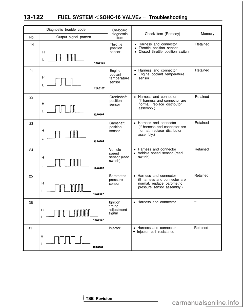
Diagnostic trouble codeOn-board
diagnostic Check item (Remedy) Memory
No.Output signal pattern
item
14Throttlel Harness and connector
Retained
position l Throttle position sensor
:n
sensor l Closed throttle position switch
12Ao104
21Enginel Harness and connector
Retained
coolant l Engine coolant temperature
Cnn
temperature
sensor
sensor
lzAO107
22Crankshaft l Harness and connector
Retained
position (If harness and connector are
:nn
sensor normal, replace distributor
assembly.)
lzAOlO7
23Camshaft l Harness and connector
Retained
position (If harness and connector are
:-
sensor normal, replace distributor
assembly.)
12Ao107
24 Vehiclel Harness and connector
Retained
speed l Vehicle speed sensor (reed
Hsensor (reed
switch)
switch)
LULl-uulnlzAO107
25
H
Barometric
pressure l Harness and connector
(If harness and connector are
LULMlvul
sensor normal, replace barometric
pressure sensor assembly.)
VA0107
Retained
36 Ignition
l Harness and connector
-
timingH
Lu u LnllMnn
adjustment
signal
12Ao107
41Injector l Harness and connector0 Injector coil resistance Retained
12Ao107
1 TSB Revision
Page 265 of 1273
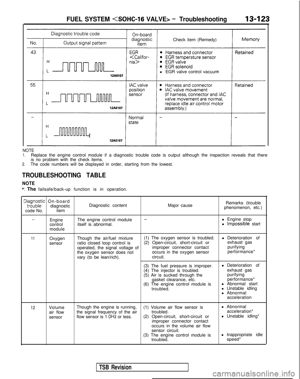
Check item (Remedy)
l EGR valve control vacuumFUEL SYSTEM
NOTE1.Replace the engine control module if a diagnostic trouble code is output\
although the inspection reveals that there
is no problem with the check items.
2.The code numbers will be displayed in order, starting from the lowest.
TROUBLESHOOTING TABLE
NOTE *:
The failsafe/back-up function is in operation.
DE;;;zic On-board
diagnostic
code No. item Diagnostic content
Major causeRemarks (trouble
phenomenon, etc.)
EngineThe engine control module--l Engine stop
control itself is abnormal. l Impossible start
module
11Oxygen
sensor Though the air/fuel mixture
(1) The oxygen sensor is troubled.
l Deterioration of
ratio closed loop control is (2) Open-circuit, short-circuit or exhaust gas
operated, the signal voltage of improper connector contact purifying
the oxygen sensor does not occurs in the oxygen sensor performance*
vary (to be lean/rich). circuit.
(3) The fuel pressure is improper. l Deterioration of
(4) The injector is troubled. exhaust gas
(5) Air is sucked through the purifying
gasket clearance, etc. performance*
(6) The engine control module is l Abnormal start
troubled. l Unstable idling
l Abnormal
acceleration
12Volume
air flow
sensor Though the engine is running,
(1) Volume air flow sensor is l Abnormal
the signal frequency of the air troubled. acceleration*
flow sensor is 1
OHz or less. (2) Open-circuit, short-circuit or l Unstable idling*
improper connector contact
occurs in the volume air flow
sensor circuit.
(3) The engine control module is l Inappropriate idle
troubled. speed*
TSB Revision
Page 266 of 1273
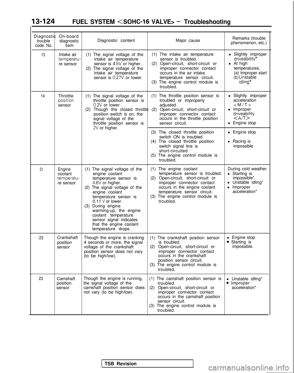
13-124FUEL SYSTEM
Diagnostic On-board
trouble diagnostic
code No.item Diagnostic content
Major causeRemarks (trouble
phenomenon, etc.)
13
14Intake air (1) The signal voltage of the (1) The intake air temperature
l Slightly impropertemperatu-intake air temperature
sensor is troubled.driveability*
re sensorsensor is 4.5V or higher.(2) Open-circuit, short-circuit or
l At high
(2) The signal voltage of the improper connector contacttemperatures,
intake air temperature occurs in the air intake (a) Improper start
sensor is
0.27V or lower. temperature sensor circuit.
(3) The engine control module isiWJ;sn$aple
troubled.
Throttle (1) The signal voltage of the (1) The throttle position sensor is
l Slightly improperposltion
throttle position sensor is troubled or improperly acceleration
sensor
0.2V or lower. adjusted.
(2) Though the closed throttle (2) Open-circuit, short-circuit or l Improper
position switch is on, the improper connector contact
signal voltage of the occurs in the throttle position
d&eTbQ
throttle position sensor is
sensor circuit. l Engine stop2V or higher.
(3) The closed throttle position l Engine stop
switch ON is troubled.
(4) The closed throttle position l Racing is
switch signal line is impossible
short-circuited.
(5) The engine control module is
troubled.
21Engine(1) The signal voltage of the (1) The engine coolant
During cold weather
coolant engine coolant temperature sensor is troubled.
l Starting is
temperatu-temperature sensor is(2) Open-circuit, short-circuit or
impossible*.
re sensor4.6V or higher. improper connector contact l Unstable idling*
(2) The signal voltage of the occurs in the engine coolant
l Improper
engine coolant temperature sensor circuit. acceleration*
temperature sensor is (3) The engine control module is
0.11
V or lower. troubled.
(3) During engine warming-up, the engine
coolant temperature
sensor signal indicates
that the engine coolant
temperature drops.
22Crankshaft Though the engine is cranking (1) The crankshaft position sensor l Engine stop
position 4 seconds or more, the signal is troubled.0 Starting is
sensor voltage of the crankshaft (2) Open-circuit, short-circuit or impossible.
position sensor does not vary improper connector contact
(to be high/low). occurs in the crankshaft
position sensor circuit.
(3) The engine control module is
troubled.
23Camshaft Though the engine is running,(1) The camshaft position sensor is
l Unstable idling*
position the signal voltage of the
troubled.0 Improper
sensor camshaft position sensor does
(2) Open-circuit, short-circuit or acceleration*
not vary (to be high/low). improper connector contact
occurs in the camshaft position
sensor circuit.
(3) The engine control module is
troubled.
TSB Revision
Page 267 of 1273
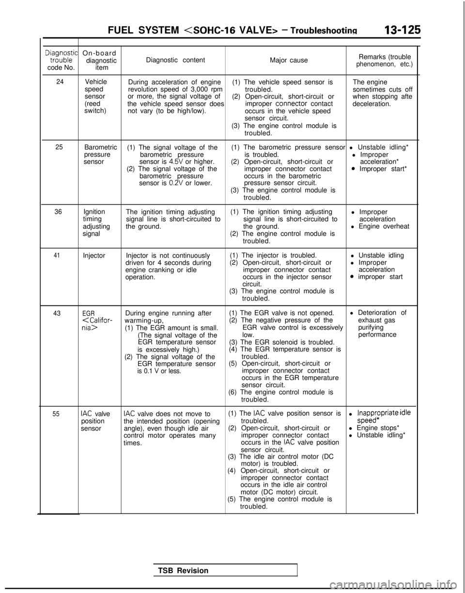
FUEL SYSTEM
Dta,i;o;ic On-board
diagnostic
code No. item Diagnostic content
Major causeRemarks (trouble
phenomenon, etc.)
24
Vehicle
speed
sensor
(reed
switch) During acceleration of engine
(1) The vehicle speed sensor is The engine
revolution speed of 3,000 rpm troubled.sometimes cuts off
or more, the signal voltage of (2) Open-circuit, short-circuit or when stopping afte
the vehicle speed sensor does improper connector
contact
deceleration.
not vary (to be high/low). occurs in the vehicle speed
sensor circuit.
(3) The engine control module is troubled.
25Barometric (1) The signal voltage of the (1) The barometric pressure sensor l Unstable idling*
pressure barometric pressure is troubled. l Improper
sensor sensor is
4.5V or higher.(2) Open-circuit, short-circuit or acceleration*
(2) The signal voltage of the improper connector contact0 Improper start*
barometric pressure occurs in the barometric
sensor is
0.2V or lower. pressure sensor circuit.
(3) The engine control module is troubled.
36Ignition
timing
adjusting
signal The ignition timing adjusting
(1) The ignition timing adjusting
l Improper
signal line is short-circuited to signal line is short-circuited toacceleration
the ground. the ground.l Engine overheat
(2) The engine control module is troubled.
41Injector Injector is not continuously
driven for 4 seconds during
engine cranking or idle
operation. (1) The injector is troubled.
(2) Open-circuit, short-circuit or improper connector contact
occurs in the injector sensor
circuit. l Unstable idling
l Improper acceleration
0 improper start
(3) The engine control module is troubled.
43EGRDuring engine running after (1) The EGR valve is not opened. l Deterioration of
purifying
(The signal voltage of the low. performance
EGR temperature sensor (3) The EGR solenoid is troubled.
is excessively high.) (4) The EGR temperature sensor is
(2) The signal voltage of the troubled.
EGR temperature sensor (5) Open-circuit, short-circuit or
is 0.1 V or less.improper connector contact
occurs in the EGR temperature
sensor circuit.
(6) The engine control module is
troubled.
55IAC valveIAC valve does not move to (1) The IAC valve position sensor is
position the intended position (opening troubled.l ;papp$Priate idle
sensor angle), even though idle air (2) Open-circuit, short-circuit or
l Engine stops*
control motor operates many improper connector contactl Unstable idling*
times. occurs in the
IAC valve position
sensor circuit.
(3) The idle air control motor (DC
motor) is troubled.
(4) Open-circuit, short-circuit or
improper connector contact
occurs in the idle air control
motor (DC motor) circuit.
(5) The engine control module is
troubled.
TSB Revision
Page 268 of 1273
13-126FUEL SYSTEM
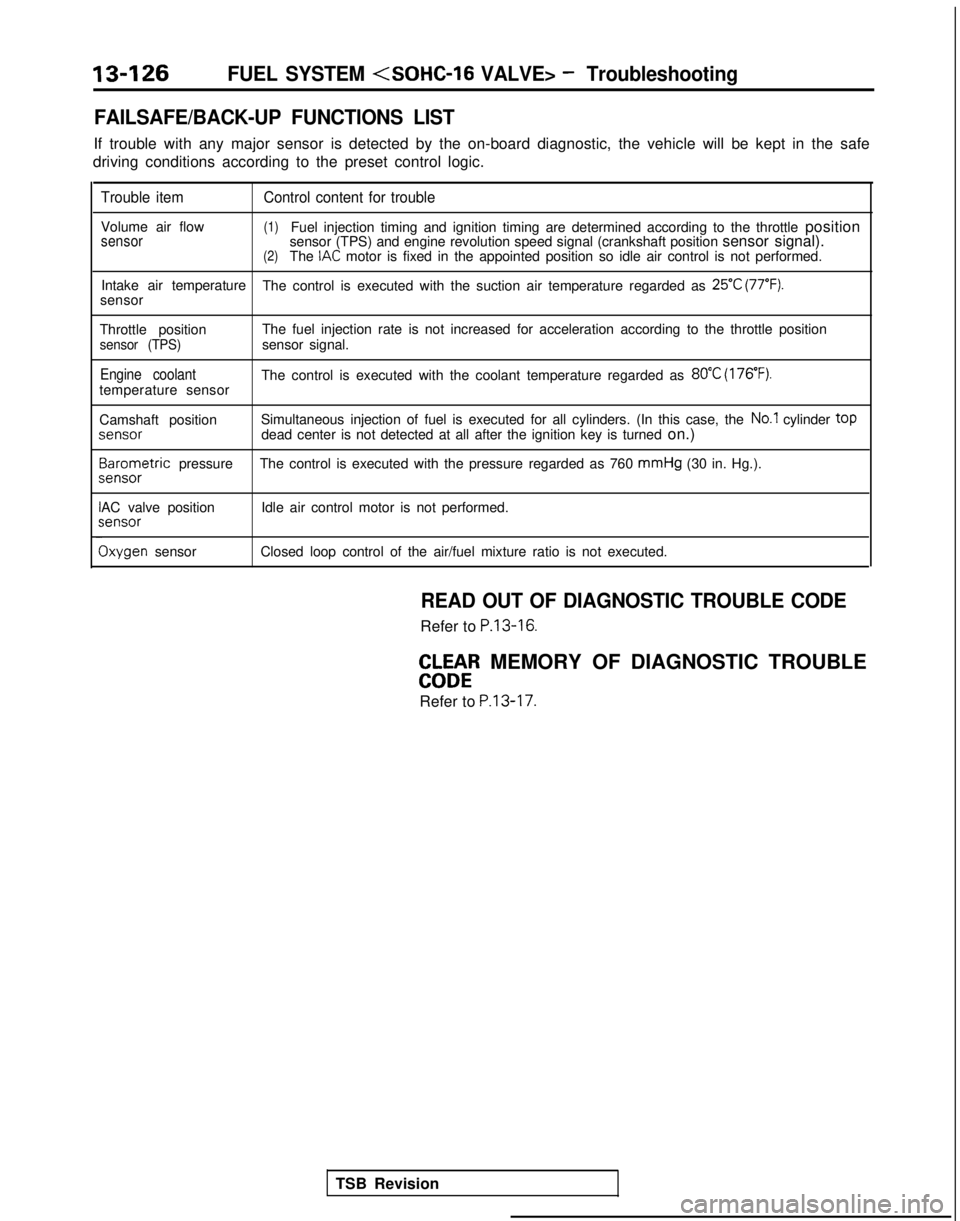
FAILSAFE/BACK-UP FUNCTIONS LIST
If trouble with any major sensor is detected by the on-board diagnostic,\
the vehicle will be kept in the safe
driving conditions according to the preset control logic.
Trouble item Control content for trouble
Volume air flow(1)Fuel injection timing and ignition timing are determined according to th\
e throttle positionsensorsensor (TPS) and engine revolution speed signal (crankshaft position \
sensor signal).(2)The IAC motor is fixed in the appointed position so idle air control is not per\
formed.
Intake air temperature The control is executed with the suction air temperature regarded as
25°C (77°F).sensor
Throttle position The fuel injection rate is not increased for acceleration according to t\
he throttle position
sensor (TPS)sensor signal.
Engine coolantThe control is executed with the coolant temperature regarded as 80°C (176’F).temperature sensor
Camshaft positionSimultaneous injection of fuel is executed for all cylinders. (In this \
case, the
No.1 cylinder top
jenS0r
dead center is not detected at all after the ignition key is turned
on.)3arometric
pressure The control is executed with the pressure regarded as 760 mmHg
(30 in. Hg.).
sensor
AC valve position Idle air control motor is not performed.;ensor
Ixygen sensor
Closed loop control of the air/fuel mixture ratio is not executed.
READ OUT OF DIAGNOSTIC TROUBLE CODE
Refer to P.13-16.
EbW&R MEMORY OF DIAGNOSTIC TROUBLE
Refer to
P.13-17.
TSB Revision
Page 269 of 1273
FUEL SYSTEM
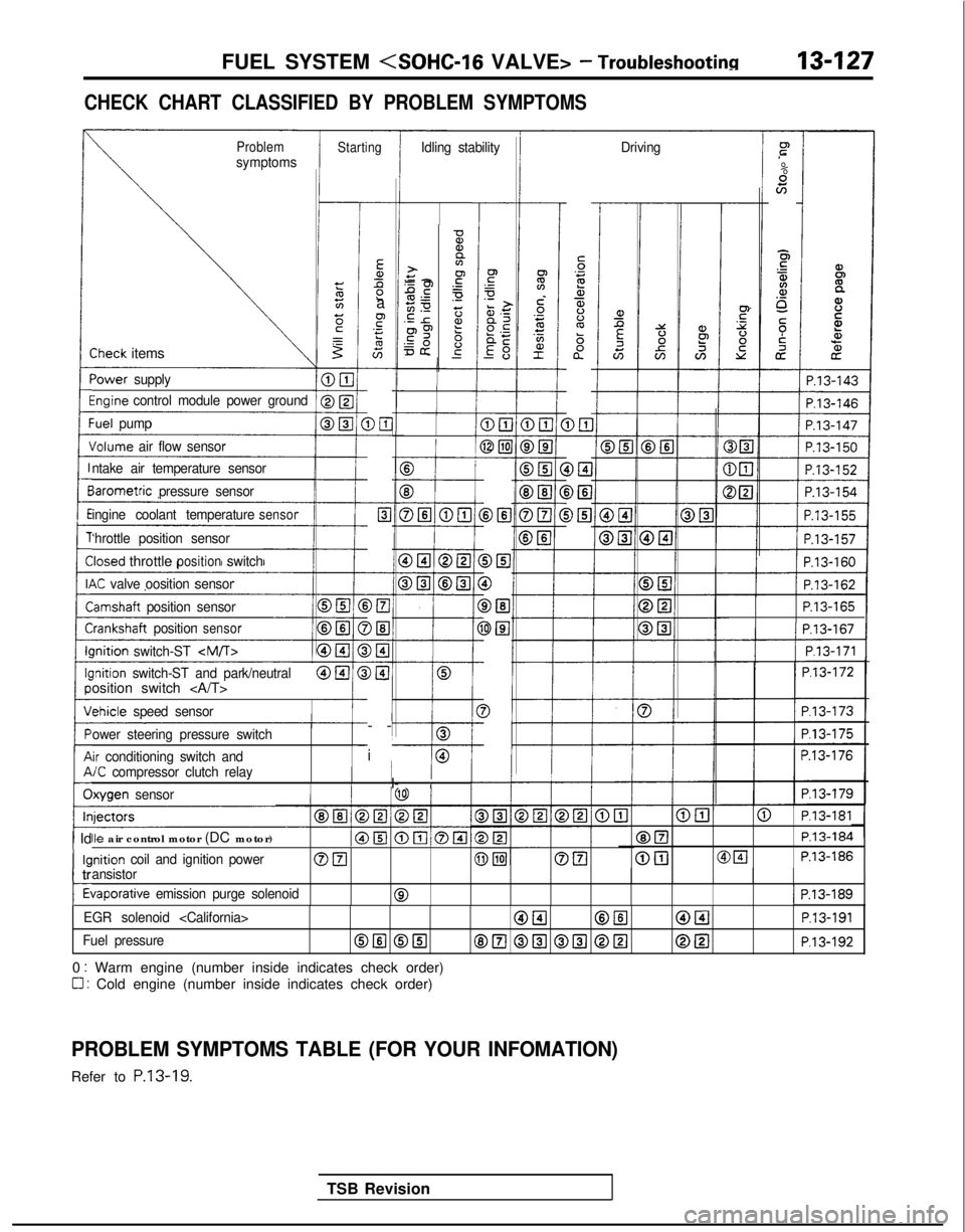
CHECK CHART CLASSIFIED BY PROBLEM SYMPTOMS
ProblemsymptomsStartingIdling stability Drivingr”
.-
%scn
E5
$4.a,o_
5;i
cz
iP.13-143
-
Ea,Ll2a
F.- s
G-
DE-
c-
Elc
-
-
>El
)El-
)I3-
)@I
I-
-
i
-
5‘32a,$%ba”
D&l DEI
i>El
-0%,a>+y -2.gPE.-50 z.E r2?p9 6=& g-
-
-Sheck items
‘ower
supply
%ginecontrol module power groundI
1 P.13-146
:uel pump
Jolume air flow sensor
B
f
E3
DELI @El
cP.13-162
P.13-165III P.13-167I
1/ P.l3-171 1
P.l3-172
P.l3-173
P.l3-175
P.13-176
P.l3-179
ntake air temperature sensor
BIB
DEI
0
DEl
3El
3
-I
iarometric
pressure sensor
ingine coolant temperature
sensor
‘hrottle position sensor
Iosed throttlepositionswitch
K valve oosition sensor
lamshaft position sensor
i-:rankshaft positionsensorIIlnition
switch-ST
-I---0lnition switch-ST and park/neutralosition switch
chicle
speed sensor
ower steering pressure switch
ir conditioning switch and/C compressor clutch relayI/I- IIlxygen sensor
@El@ P.l3-181
@ElP.13-184
@[email protected]
Ile air control motor (DC motor)
inition coil and ignition powerOFI@piJOEIansistor
tiaporative emission purge solenoid01 P.13-189
1 Id
kl
c
tr
t
EGR solenoid
Fuel pressureOIlI @El8E.l @El @El @[email protected]
0 : Warm engine (number inside indicates check order)
0 : Cold engine (number inside indicates check order)
PROBLEM SYMPTOMS TABLE (FOR YOUR INFOMATION)
Refer to P.13-19.
TSB Revision
Page 270 of 1273
13-128FUEL SYSTEM
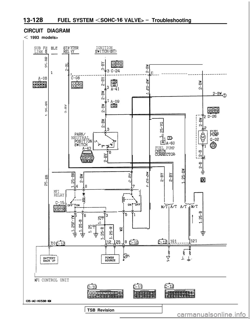
CIRCUIT DIAGRAM
< 1993 models>
IGNITIONSWITCH(ST)
I
SUB F'JILINK @
2
Licl
36
0
Ct\J.---------------~------------------.,\A-08C-08
I@34
m
2i
‘I
12
El3 A343
L6670lru
I
c;
BLE E-w
E
c!1
2
c:
3.____ --------------q-w-
1
___--_--q-w
?
+d
PARK/NEUTRALKlJ;;ON“1EbLYP&I
A-433’ .aAA-60
FUEL PUMP
k%%&TOR
-+
iI
kcJ
i
:
7:-MFIRELAY1
c-15
6
T
T
gl?3
;.
R.i
3
KY !x ry-8.Akc;c
s
-
1oa
-
J-Q
6
MFI CONTROL UNIT
t35-AC-HOW-WY
1 TSB Revision