MITSUBISHI GALANT 1989 Service Repair Manual
Manufacturer: MITSUBISHI, Model Year: 1989, Model line: GALANT, Model: MITSUBISHI GALANT 1989Pages: 1273, PDF Size: 37.62 MB
Page 321 of 1273
On-Vehicle Inspection of MFI
FUEL SYSTEM
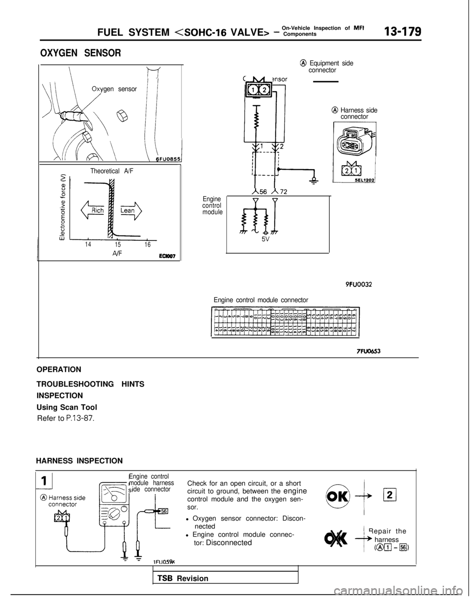
OXYGEN SENSOR
\l-f
\
Oxygen sensor
J
q :
i’ 1%
Lkm uA6FUO6.5
2
8
.5
s.-EE?za,w
Theoretical A/F
14 1516
4/FEClW7
j5
Engine
control module
@ Equipment side
connector
iIxy;n se;‘i,G,
A56 h72
fhx 5v
@ Harness side
connector
9FUOO32
Engine control module connector
7FL0553
OPERATION
TROUBLESHOOTING HINTS
INSPECTION
Using Scan Tool Refer to
P.13-87.
HARNESS INSPECTION
Engine control
module harness ide connector
56
1’r YlFUO5%
Check for an open circuit, or a short
circuit to ground, between the engine
control module and the oxygen sen-
sor.
l Oxygen sensor connector: Discon-
nected
l Engine control module connec-
tor: Disconnected
cl OK+02
’ Repair the
A harness
( @El-@I)
TSB Revision
Page 322 of 1273
13-180FUEL SYSTEM
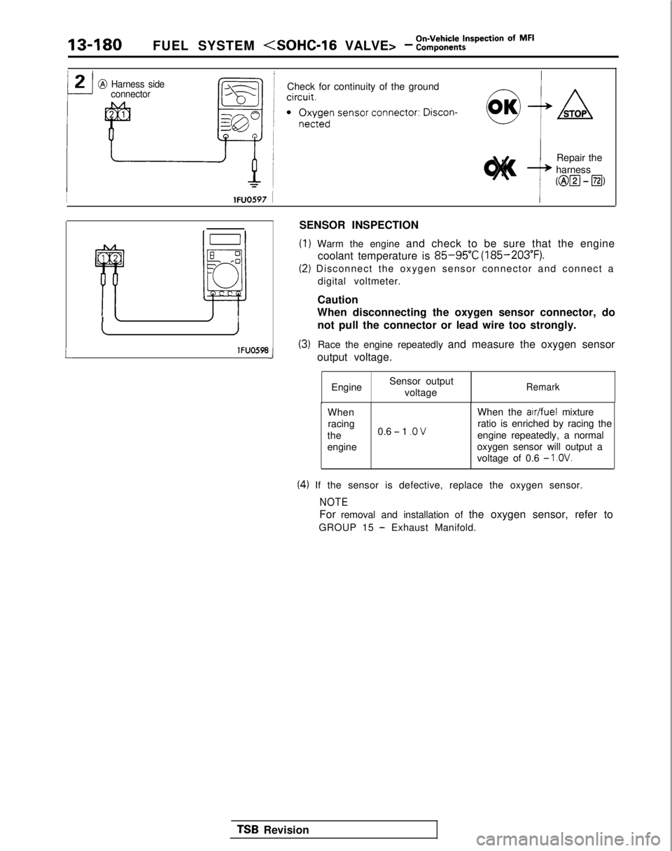
@ Harness sideconnectorCheck for continuity of the ground
Repair the
harness
(@lzl - El)
IlFUOS97 1I
L
G-lI’ ‘Ila
r rI L/I
IJ
lFUO598J
SENSOR INSPECTION
(I) Warm the engine and check to be sure that the engine
coolant temperature is
85-95°C (185-203°F).
(2) Disconnect the oxygen sensor connector and connect a
digital voltmeter.
Caution
When disconnecting the oxygen sensor connector, do
not pull the connector or lead wire too strongly.
(3)Race the engine repeatedly and measure the oxygen sensor
output voltage.
Engine Sensor output
voltage
Remark
When When the a/r/fuel
mixture
racing
the 0.6
- 1 .O Vratio is enriched by racing the
engine repeatedly, a normal
engine oxygen sensor will output a
voltage of 0.6
- 1 .OV.
(4) If the sensor is defective, replace the oxygen sensor.
NOTE
For removal and installation of the oxygen sensor, refer to
GROUP 15
- Exhaust Manifold.
TSB Revision
Page 323 of 1273
FUEL SYSTEM
Of MF’13-181
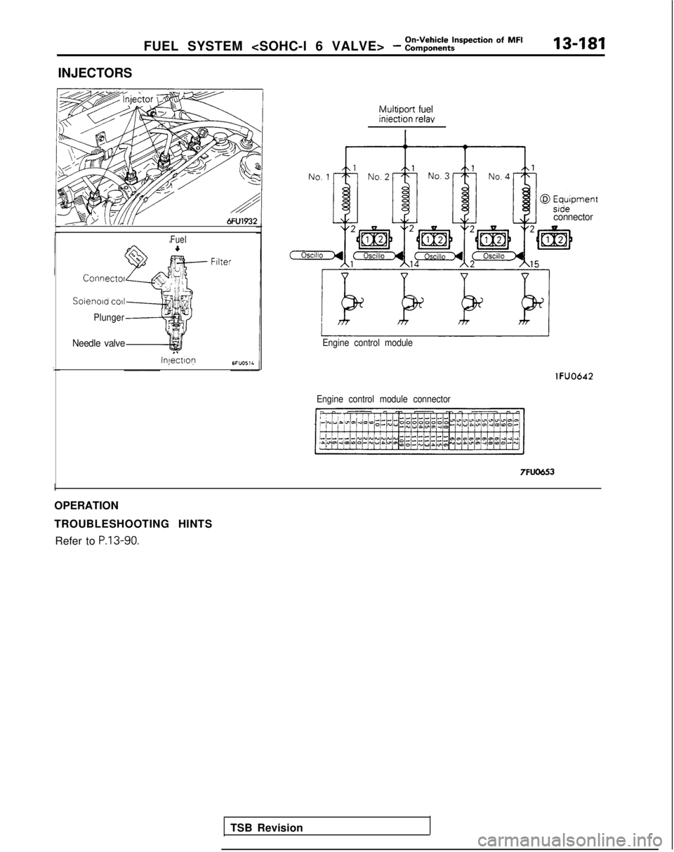
INJECTORS
Fuel
Connect01
Soienold co11
Plunger
Needle valve
Injectlop
Multiport fueliniection relay
TSB Revision
connector
Engine control module
Engine control module connector
lFUO642 7FUO653
I
OPERATION
TROUBLESHOOTING HINTS
Refer to
P.13-90.
Page 324 of 1273
13-182FUEL SYSTEM
INSPECTION
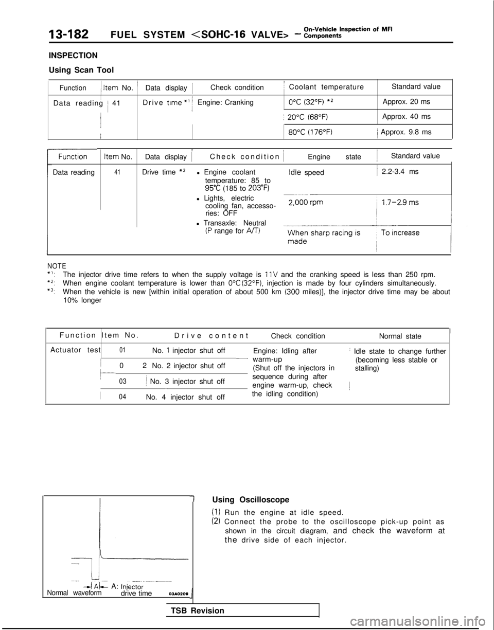
Using Scan Tool
Function1 Item
No. ’Data display 1Check conditionI Coolant temperature Standard value
IData reading / 41Drive trme
*’ 1Engine: Cranking0°C (32°F) *2Approx. 20 ms
j: 20°C (68°F)Approx. 40 ms 80°C
(176°F)/ Approx. 9.8 ms
Data reading
NOTE Item
No.
41 i
Data display 1
Check condition
IEngine state 1Standard value
Drive time
*3l Engine coolant temperature: 85 to
95°C (185 to 203°F)
l Lights, electric cooling fan, accesso-ries: OFF
l Transaxle: Neutral
(P range for AIT) Idle
speed
1 2.2-3.4 ms
*‘:The injector drive time refers to when the supply voltage is 11 V and the cranking speed is less than 250 rpm.
*2:When engine coolant temperature is lower than 0°C (32°F). injection is made by four cylinders simultaneously.
*3:When the vehicle is new [within initial operation of about 500 km (300 miles)], the injector drive time may be about
10% longer
Function Item No
.
Drive content Check condition Normal state
Actuator test
01No. 1 injector shut off Engine: Idling afterI Idle state to change further
0
2
No. 2 injector shut off
- warm-up
(becoming less stable or
(Shut off the injectors in stalling)
03li No. 3 injector shut off sequence during after-engine warm-up, check1
I04No. 4 injector shut off
the idling condition)
-k
Imp
4 AL A: Inje,t,r--m--m-Normal waveformdrive time03*0209
(1) Run the engine at idle speed.
(2) Connect the probe to the oscilloscope pick-up point as
shown in the circuit diagram, and check the waveform at
the drive side of each injector.
1
TSB Revision 1
Using Oscilloscope
Page 325 of 1273
FUEL SYSTEM
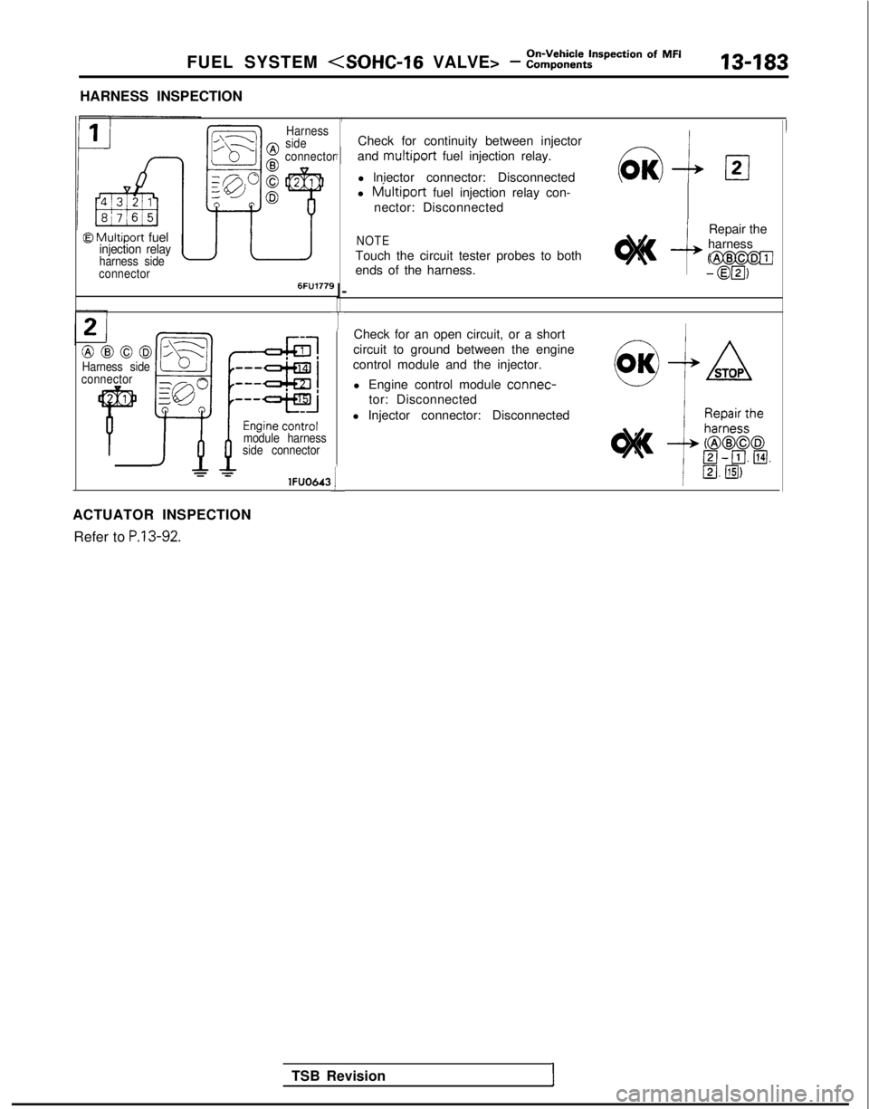
HARNESS INSPECTION
@ Multiport fuelinjection relayharness side
connector
,\---L
Ell---l0
!I?
pJ”
D
Harness
side
connector
6FU1779
@@@03Harness side
connector
1
Pmodule harness
side connector
=lFUO643
ACTUATOR INSPECTION
Refer to
P.13-92.
r I
I-
T
L
Check for continuity between injector
and
multiport fuel injection relay.
l lniector connector: Disconnected
l
tviultiport fuel injection relay con-
nector: Disconnected
NOTE
Touch the circuit tester probes to both
ends of the harness. Repair the
harnessCm
- 0@3,
Check for an open circuit, or a short
circuit to ground between the engine
control module and the injector.
l Engine control module connec-
tor: Disconnected
l Injector connector: Disconnected
TSB Revision
I
Page 326 of 1273
13-184
On-Vehicle Inspection of MFI
FUEL SYSTEM (SOHC-16 VALVE> - Components
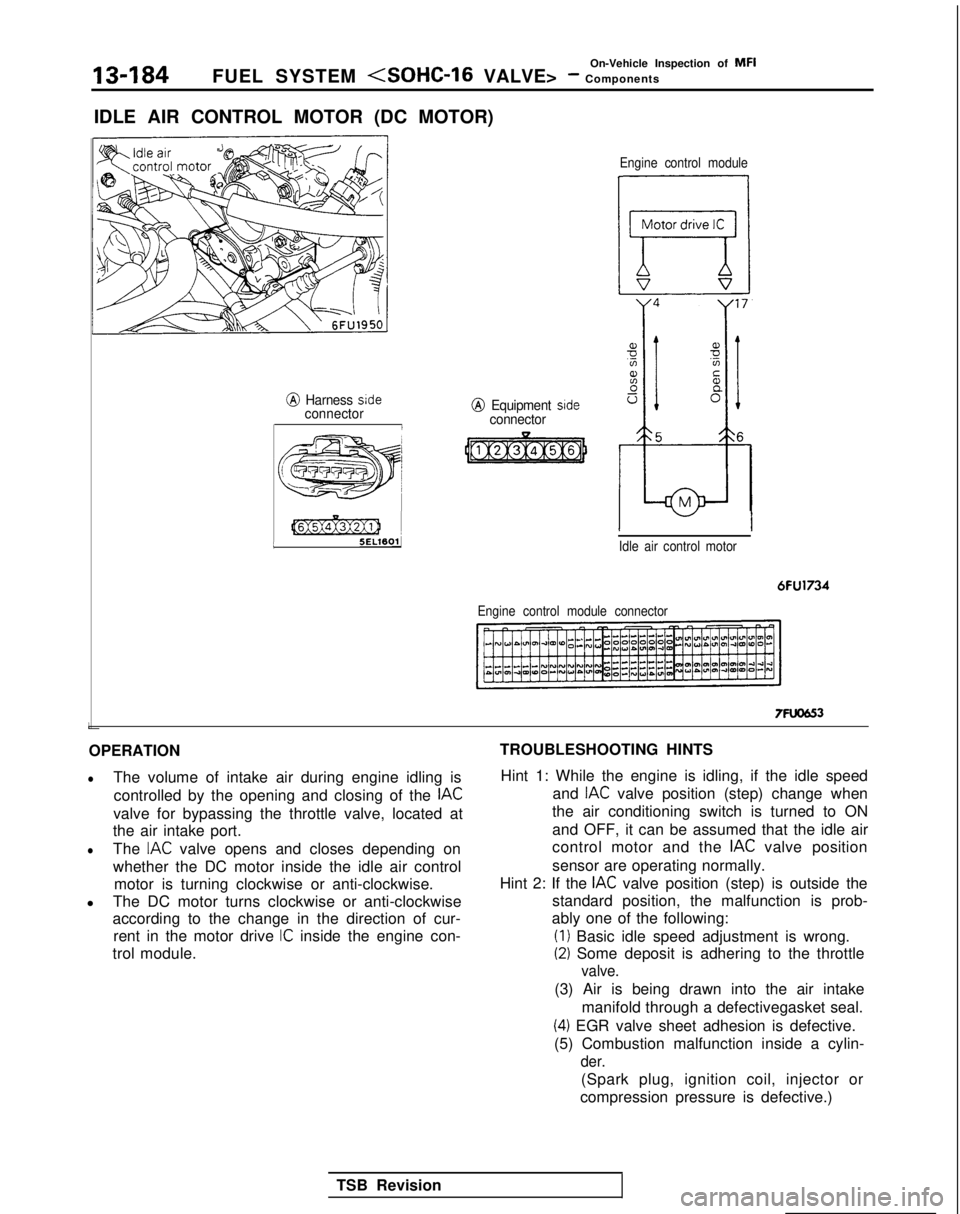
IDLE AIR CONTROL MOTOR (DC MOTOR)
@ Harness sideconnectorI L
[@Ex@ziJ 1
5ELWOlJ
j
e;
j 55ww3 )A’,’/
@ Equipment sideconnector
Engine control module
Idle air control motor
6FU1734
Engine control module connector
7FUCJG3
OPERATION
lThe volume of intake air during engine idling is controlled by the opening and closing of the
IAC
valve for bypassing the throttle valve, located at
the air intake port.
lThe IAC valve opens and closes depending on
whether the DC motor inside the idle air control motor is turning clockwise or anti-clockwise.
l The DC motor turns clockwise or anti-clockwise
according to the change in the direction of cur-
rent in the motor drive
IC inside the engine con-
trol module. TROUBLESHOOTING HINTS
Hint 1: While the engine is idling, if the idle speed and
IAC valve position (step) change when
the air conditioning switch is turned to ON
and OFF, it can be assumed that the idle air
control motor and the
IAC valve position
sensor are operating normally.
Hint 2: If the
IAC valve position (step) is outside the
standard position, the malfunction is prob-
ably one of the following: (I)
Basic idle speed adjustment is wrong.
(2) Some deposit is adhering to the throttle
valve.
(3) Air is being drawn into the air intake
manifold through a defectivegasket seal.
(4) EGR valve sheet adhesion is defective.
(5) Combustion malfunction inside a cylin-
der.
(Spark plug, ignition coil, injector or
compression pressure is defective.)
TSB Revision
Page 327 of 1273
FUEL SYSTEM
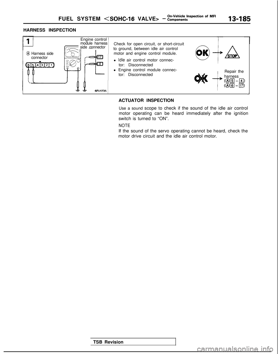
HARNESS INSPECTION
@ Harness side
connector
Engine control )module harness
side connector
- -6FU1735
Check for open circuit, or short-circuit
to ground, between idle air control motor and engine control module.
l
Idle air control motor connec-
tor: Disconnected
l Engine control module connec- tor: Disconnected0 OKSA
STOP
Repair the
harness
ml - El)
Km - El)
J
ACTUATOR INSPECTION
Use a sound scope to check if the sound of the idle air control
motor operating can be heard immediately after the ignition
switch is turned to “ON”.
NOTE
If the sound of the servo operating cannot be heard, check the
motor drive circuit and the idle air control motor.
TSB Revision
Page 328 of 1273
13-186On-Vehicle Inspection of MFI
FUEL SYSTEM
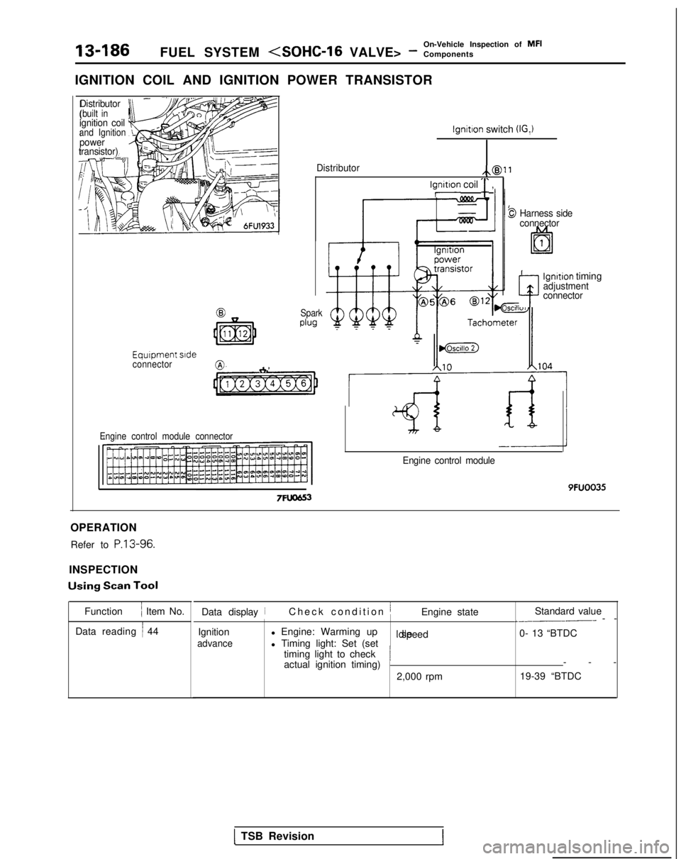
IGNITION COIL AND IGNITION POWER TRANSISTOR
-Distributor(built inignition coiland Ignitionpower
transistor)
Equrpment srdeconnector8”
Engine control module connector Spark
plug
Iynitron coil ‘r ,
lgnitron switch (IG,)
Distributor/,@)f1
9 Harness side
connector
4
lgnrtion timingadjustment
connector
7FU0653
Engine control module 9FUOO35
OPERATION Refer to
P.13-96.
INSPECTION Using
Scan Tool
Function
/ Item No.
Data reading
i 44 Data display
iCheck condition jEngine state
Standard value_.-___-- -
-
Ignition
advance
l Engine: Warming up Idle speed
0- 13 “BTDC
l Timing light: Set (set
timing light to check
actual ignition timing)
/--
-
2,000 rpm 19-39 “BTDC
1 TSB Revision1
Page 329 of 1273
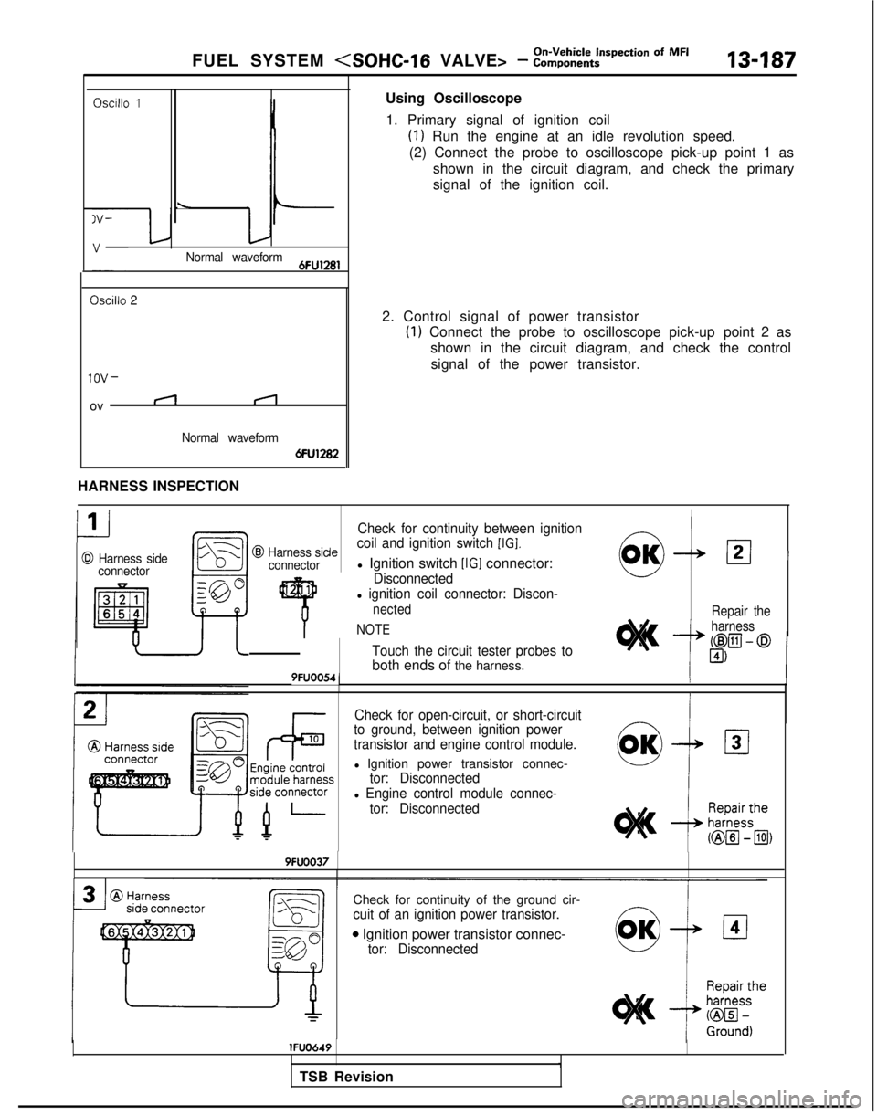
FUEL SYSTEM
\
Normal waveform6FU1281
Oscillo 2
lOV-
ovII
Normal waveform
6FU1282
HARNESS
INSPECTION Using Oscilloscope
1. Primary signal of ignition coil
(1) Run the engine at an idle revolution speed.
(2) Connect the probe to oscilloscope pick-up point 1 as shown in the circuit diagram, and check the primary
signal of the ignition coil.
2. Control signal of power transistor
(I) Connect the probe to oscilloscope pick-up point 2 as
shown in the circuit diagram, and check the control
signal of the power transistor.
CI1
@ Harness side connector
Check for continuity between ignition
‘R/4(21 I@I Harness siclecoil and ignition switch [IGI.
connectorl Ignition switch [IGI connector:/,‘\0”
Disconnected1
4
l ignition coil connector: Discon-
nected
NOTE
Touch the circuit tester probes to
both ends of the harness.19FUOO54,/I
Repair the
harness
_A- h
Check for open-circuit, or short-circuit
to ground, between ignition power
transistor and engine control module.
l Ignition power transistor connec-
tor: Disconnected
l Engine control module connec-
tor: Disconnected
9FUOO37
Check for continuity of the ground cir-
cuit of an ignition power transistor.
0 Ignition power transistor connec-
tor: Disconnected lFUO649
TSB Revision
Page 330 of 1273
-i4
@Harness side
connector
/
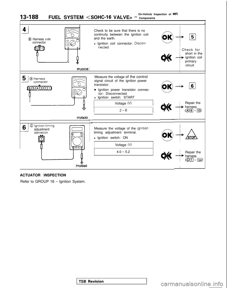
Check to be sure that there is no
continuity between the ignition coil
and the earth.
l Ignition coil connector: Discon-
netted/ Check fo
r
short in the
ignition coil
primary
/ circuit
9FUOO38 1
13-188
On-Vehicle Inspection of MFI
FUEL SYSTEM
6
I
--
ml---X
A!
g@
0
T lFUO650
lgnltion
tlmlngadjustment
connector
E-:1
ll!?!
* 7FU1060
L
Measure the voltage of the control
signal circuit of the ignition power
transistor.
0 Ignition power transistor connec- tor: Disconnected
l Ignition switch: START
Voltage
(VI I
Measure the voltage of the ignrtion
timing adjustment terminal.
l Ignition switch: ON
Voltage
(VI
0 OKlIzI6
Repair the
harness
(@El - Ial
4.0 - 5.2
ACTUATOR INSPECTION Refer to GROUP 16
- Ignition System. Repair the
harness
(@El - 11041)
TSB RevisionI