MITSUBISHI GALANT 1989 Service Repair Manual
GALANT 1989
MITSUBISHI
MITSUBISHI
https://www.carmanualsonline.info/img/19/57312/w960_57312-0.png
MITSUBISHI GALANT 1989 Service Repair Manual
Trending: ECO mode, jump start, Idle, radio, brake, headlamp, change wheel
Page 281 of 1273
FUEL SYSTEM - ?::;:r%t~pection Of MF’13439
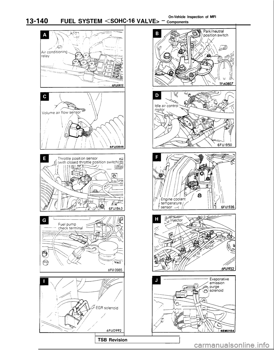
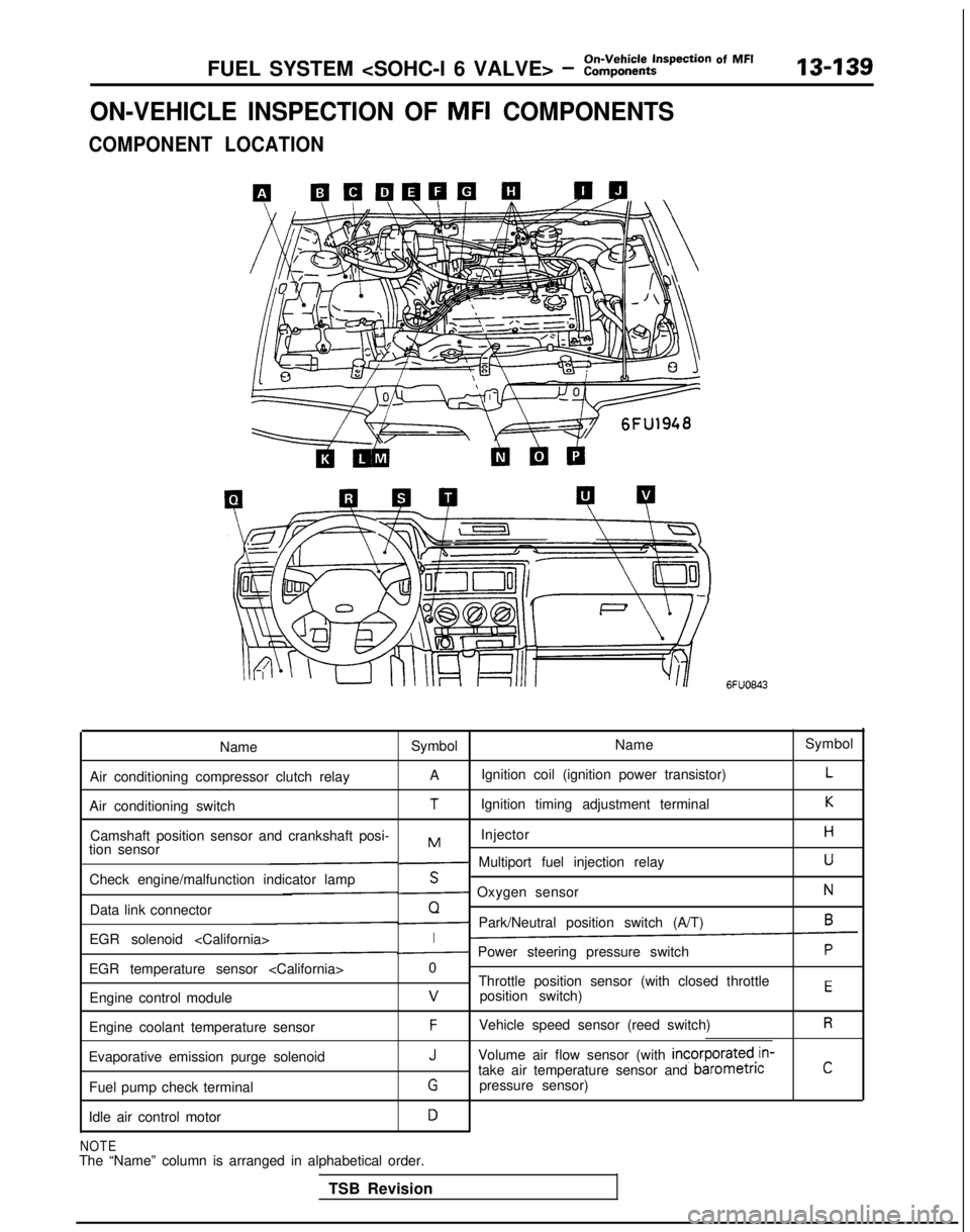
ON-VEHICLE INSPECTION OF MFI COMPONENTS
COMPONENT LOCATION
6FUO843
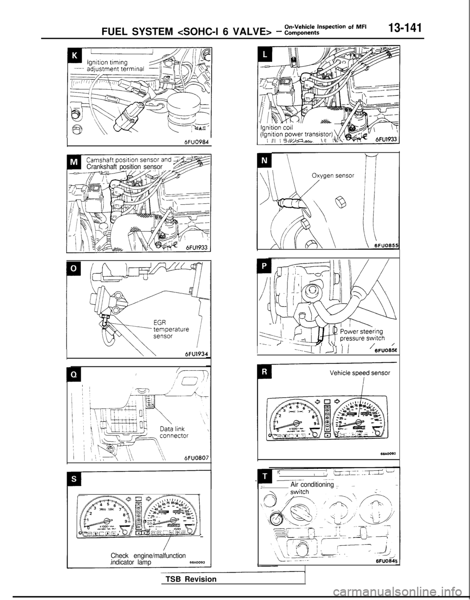
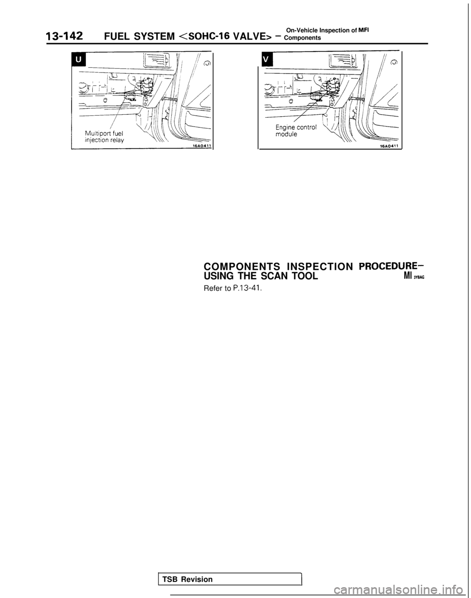
Name Symbol NameSymbol
Air conditioning compressor clutch relay A
Ignition coil (ignition power transistor)
L
Air conditioning switchTIgnition timing adjustment terminalK
Camshaft position sensor and crankshaft posi- InjectorHMtion sensor- Multiport fuel injection relayU
Check engine/malfunction indicator lampS- Oxygen sensorN
Data link connectorQ- Park/Neutral position switch (A/T)6
EGR solenoid I- Power steering pressure switchP
EGR temperature sensor 0
Throttle position sensor (with closed throttle
position switch)
EEngine control modulev
Engine coolant temperature sensorFVehicle speed sensor (reed switch)R
Evaporative emission purge solenoidJVolume air flow sensor (with incorporated,in-
take air temperature sensor and barometncC
Fuel pump check terminalGpressure sensor)
Idle air control motor
D
NOTEThe “Name” column is arranged in alphabetical order. TSB Revision
Page 282 of 1273
13-140
On-Vehicle Inspection of MFI
FUEL SYSTEM
VALVE> - Components
6FU 0985
6FUO99-J
TSB Revision
Page 283 of 1273
FUEL SYSTEM - ::ii,,k:t~pection Of MF’13-141
6FuO984
Crankshaft position sensor
\\6FU193~
I(7-T
I;.’ E
,/ii
;
i
; ~&qqLk~
)
’ [,,“\,k@$&b;,,,“\
I’
/ \, pQi, >{,
1; /
‘\l>,
/\\\6FUO8Oi
,<,$+$GgT
z Jp$j&& ‘\
,
“2$---8%\.35 Fqp2; ,I <,, cLTgg.&~.
,D~~,
1sl ) g , a&&iI& I.“: :
(;-omd!gs?~ 5, gt : .“*I-- L l2,, m ‘IFiTb;qF
/Check engine/malfunction
indicator lamp68b.0093
B :iG i 1
,i mIl-
11
’ 0_;
3
(1P
I”;l-i-yCL, ,\i / ,---_ /
’ - ’ +-+j$p2E~~;:c9h
/ /I----4 ) Jj 1 1’ 6FU0656
68mosJ
I(>/
!,ij”_II. .:a L-2__--. ~-~-Air conditioning I~.~ ~..
LT. --..-6FUO64!
TSB Revision
Page 284 of 1273
On-Vehicle Inspection of MFI
13-142
FUEL SYSTEM (SOHC-16 VALVE> - Components
16AO.31116AO.311
COMPONENTS INSPECTION PROCEDURE-
USING THE SCAN TOOLMl WSAG
Refer to P.13-41.
TSB Revision1
Page 285 of 1273
On-Vehicle Inspection of MFIFUEL SYSTEM
VALVE> - Components13-143
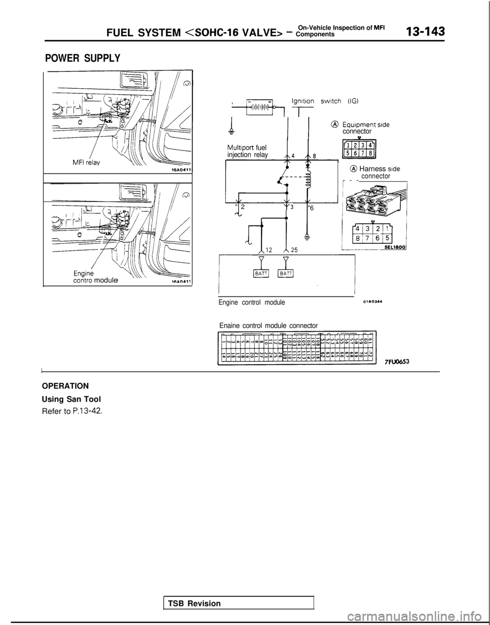
POWER SUPPLY
16AO411
contra module ,
;;lii’l’l’lb Ig;lon switch (IG)
MultIport
fuel
injection relay
/\4 /t\8
"
2
't'3 "6rt4,
Equipment sideconnector
@ Harness side
connector
--
-
Engine control module01105.4
Enaine control module connector
7FlJO653
I
OPERATION
Using San Tool Refer to
P.13-42.
TSB Revision
Page 286 of 1273
On-Vehicle Inspection of MFI
13-144FUEL SYSTEM - Components
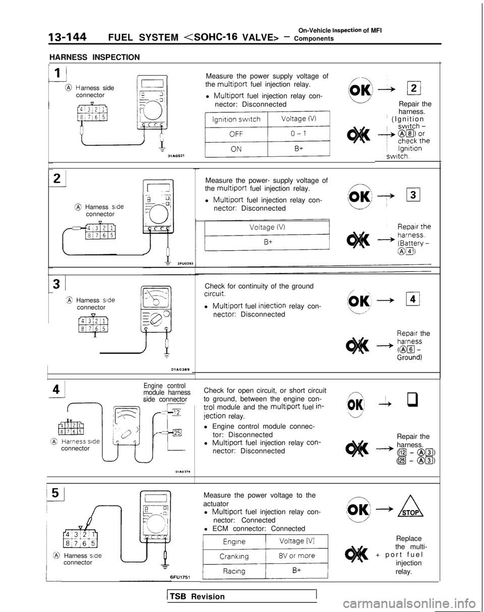
HARNESS INSPECTION
1
1 IMeasure the power supply voltage of
the
multiport fuel injection relay.
l
Multiport fuel injection relay con-
nector: Disconnected
r,
L
NC;Jr=--cl7
I
?-i3I+- c
-@ Harness side
connector
Repair the
harness. ~
(Ignition swrtch.
_J2
L5-l
Measure the power- supply voltage of
the
multiport fuel injection relay.
l
Multiport fuel injection relay con- nectar:
Disconnected @
Harness sdeconnector
3iCheck for continuity of the groundcrrcuit.
l Multiport fuel iniection
relay con- nectar:
Disconnected3 Harness side
connector
Repair theI
M.- zf$
Engine controlmodule harness
side connectorCheck for open circuit, or short circuit
to ground, between the engine con-
trol module and the multiport fuel in-
jection relay.
(03 -2 q
l Engine control module connec-
tor: Disconnected
l
Multiport fuel injection relay con-
nectar:
Disconnected Repair the
harness.
- @I
- @El, @I
- @Ia
connector
Measure the power voltage to the
actuator l
Multiport fuel injection relay con-
nector: Connected
l ECM connector: Connected
1li
Replace
the multi-
+ port fue
l
injection
Harness side
connector
relay.6FU1751
1
TSB
Revision1
Page 287 of 1273
‘On-Vehicle Inspection of MFIFUEL SYSTEM (SOHC-16 VALVE> - Components13-145
9FUOOlO
9FUOO18
1
TSB RevisionI
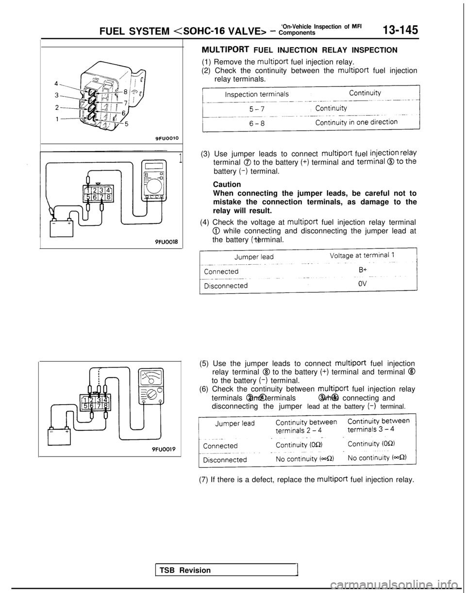
MULTIPORT FUEL INJECTION RELAY INSPECTION
(1) Remove the multiport
fuel injection relay.
(2) Check the continuity between the multiport
fuel injection
relay terminals.
(3) Use jumper leads to connect multiport
fuel
injection relay
terminal 0 to the battery (+) terminal and terminal 0 to the
battery (-)
terminal.
Caution
When connecting the jumper leads, be careful not to mistake the connection terminals, as damage to the
relay will result.
(4) Check the voltage at multiport
fuel injection relay terminal
@I while connecting and disconnecting the jumper lead at
the battery (-) terminal.
(5) Use the jumper leads to connect multiport
fuel injection
relay terminal
@I to the battery (+) terminal and terminal @
to the battery (-)
terminal.
(6) Check the continuity between multiport
fuel injection relay
terminals @-@I and terminals @-@I while connecting and
disconnecting the jumper lead at the battery
(-) terminal.
9FUOOl9
(7) If there is a defect, replace the multiport
fuel injection relay.
Page 288 of 1273
13-146FUEL SYSTEM
VALVE> - ::$:%i-- Of MF’
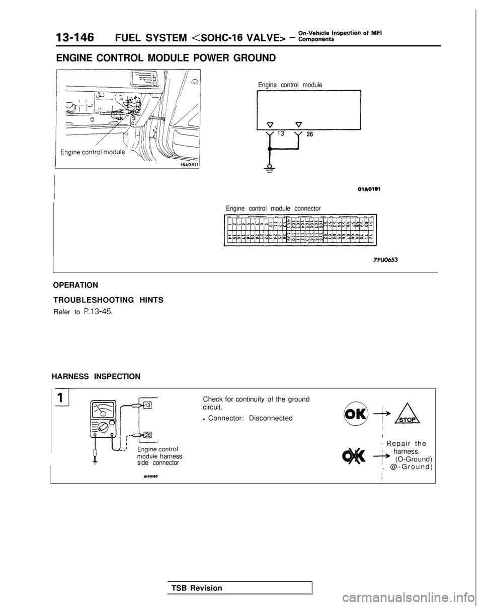
ENGINE CONTROL MODULE POWER GROUND
Engine control module
LIirzl13
Y
26
Engine control module connector
7FU06.53
OPERATION
TROUBLESHOOTING HINTSRefer to P.13-45.
HARNESS INSPECTION
mddule harnessside connector
Check for continuity of the ground
circuit.
l Connector: Disconnected
I
1 Repair th
e
harness.
e (O-Ground)
, @-Ground
)
TSB Revision
Page 289 of 1273
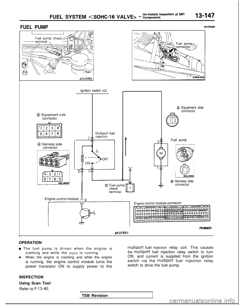
FUEL SYSTEM (SOHC-16 VALVE> - :::;::tt?ction Of MF’13-147
FUEL PUMPM13YEAB
6FUO985-
@ Equipment srdeconnector
@ Harness sideconnectorI
Ignition switch (IG)
Multiport
fuel
@I Equipment sideconnector
TSB Revision
Fuel pump-I
@ Harness sideconnector
Engine COntrOl module A 8
7Fuom 6FU1951
OPERATION
a The fuel pump is driven when the engine i
s
cranking and while the engine is running.
lWhen the engine is cranking and while the engine
is running, the engine control module turns the
power transistor ON to supply power to the
multiport fuel injection relay coil. This causes
the
multiport fuel injection relay switch to turn
ON, and current is supplied from the ignition
switch via the multiport
fuel injection relay
switch to drive the fuel pump.
INSPECTION Using Scan Tool Refer to
P.13-46.
Page 290 of 1273
On-Vehicle Inspection of MFI
13-148FUEL SYSTEM (SOHC-16 VALVE> - Components
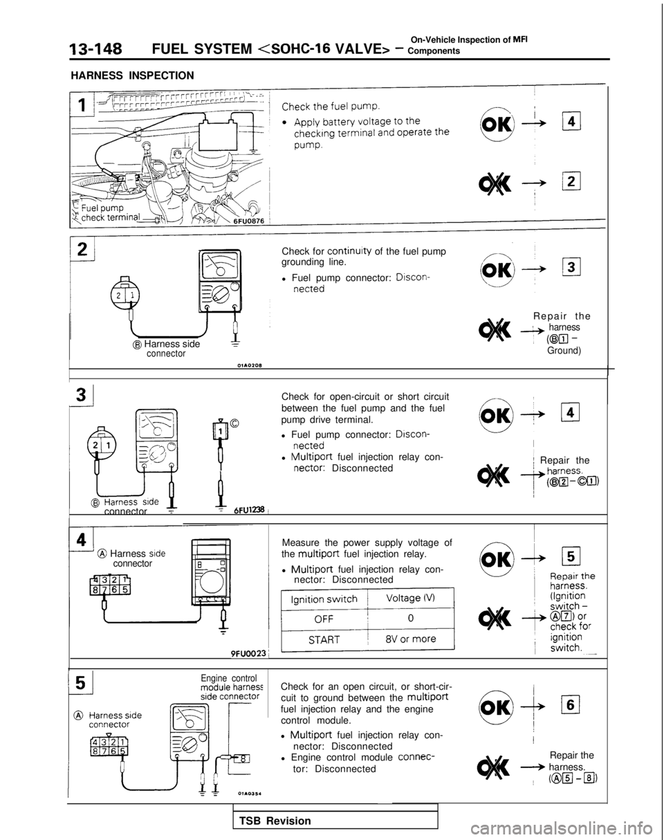
HARNESS INSPECTION
@ Harness sideconnector
Check for continuity of the fuel pump
grounding line.
l Fuel pump connector: Discon-
netted
Repair th
e
4 harness
~
@El-Ground)
Check for open-circuit or short circuit
between the fuel pump and the fuel
pump drive terminal.
l Fuel pump connector:
Drscon-
nettedl Multiport fuel injection relay con- nectar:
Disconnected
I/
2 .lr/ Repair theL^Srr,-..-r
P
9vh
connector T-y 6FU1238!
I
@ Harness srdeconnector
Measure the power supply voltage of
the
multiport fuel injection relay.
l
Multiport fuel injection relay con-
nector: Disconnected
r
9FUOO23;
IIIEngine controlCheck for an open circuit, or short-cir-
cuit to ground between the
multiport
fuel injection relay and the enginecontrol module.
l
Multiport fuel injection relay con-
nector: Disconnected
l Engine control module connec-
tor: Disconnected!
Repair the
+ harness. ~
@H-B)
TSB Revision
Trending: oil change, horn, height, fuel reserve, recommended oil, night vision, 4WD

