MITSUBISHI GALANT 1989 Service Repair Manual
Manufacturer: MITSUBISHI, Model Year: 1989, Model line: GALANT, Model: MITSUBISHI GALANT 1989Pages: 1273, PDF Size: 37.62 MB
Page 681 of 1273
MANUAL TRANSAXLE
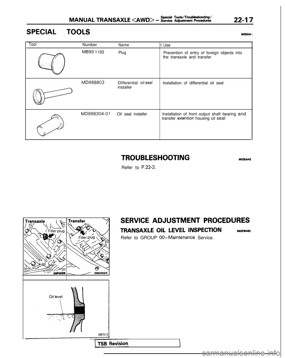
SPECIAL TOOLSMZSDA-
ToolNumberNameI Use
w
MB99
1193
r
PlugPrevention of entry of foreign objects into
the transaxle and transfer
L
MD998803Differential 011 sealInstallation of differential oil seal
t&-
installer
MD998304-0 1Oil seal installer Installation of front output shaft bearing and
transfer extention
housing oil seal
TROUBLESHOOTING
Refer to P.22-3.
M22EAAE
SERVICE ADJUSTMENT PROCEDURES
TRANSAXLE OIL LEVEL INSPECTIONm
Refer to GROUP 00-Maintenance Service.
\ //’ 09AOO24
Page 682 of 1273
22-18 MANUAL TRANSAXLE
I I09K567
09K56f
For L.H.For R.H.
Dust
5
-
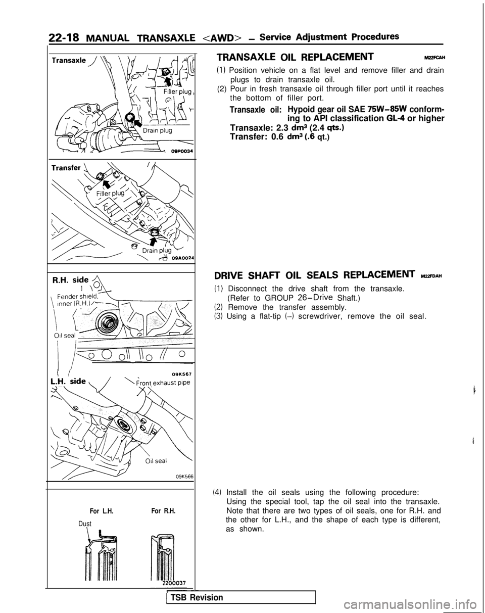
TRANSAXLE OIL REPLACEMENTM22FC.AH
(1) Position vehicle on a flat level and remove filler and drain
plugs to drain transaxle oil.
(2) Pour in fresh transaxle oil through filler port until it reaches the bottom of filler port.
Transaxle oil:Hypoid gear oil SAE 75W-85W conform-
ing to API classification GL-4 or higher
Transaxle: 2.3
dm3 (2.4 qts.)
Transfer: 0.6 dm3 (.6 qt.)
DRIVE SHAFT OIL SEALS REPLACEMENT MZZFDAH
(1) Disconnect the drive shaft from the transaxle. (Refer to GROUP
26-Drive Shaft.)
(2) Remove the transfer assembly.
(3) Using a flat-tip (-)
screwdriver, remove the oil seal.
(4) Install the oil seals using the following procedure:
Using the special tool, tap the oil seal into the transaxle.
Note that there are two types of oil seals, one for R.H. and
the other for L.H., and the shape of each type is different,
as shown.
1 TSB Revision
Page 683 of 1273
MANUAL TRANSAXLE
IL.H. side _
MC;998~3 / ()
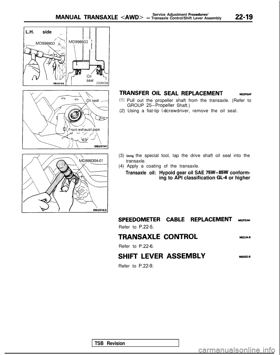
TRANSFER OIL SEAL REPLACEMENThl22FGAF
(1) Pull out the propeller shaft from the transaxle. (Refer toGROUP
25-Propeller Shaft.)
(2) Using a fiat-tip (-) screwdriver, remove the oil seal.
(3) Using the special tool, tap the drive shaft oil seal into the transaxle.
(4) Apply a coating of the transaxle.
Transaxle oil:Hypoid gear oil SAE 75W-85W conform-
ing to API classification GL-4 or higher
SPEEDOMETER CABLE REPLACEMENT ~22~
Refer to P.22-5.
TRANSAXLE CONTROL
M22JA.B
Refer to
P.22-6.
SHIFT LEVER ASSEMBLYMZZGE-8
Refer to P.22-9.
TSB Revision
Page 684 of 1273
22-20MANUAL TRANSAXLE
TRANSAXLE
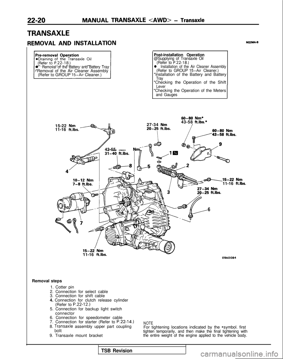
REMOVAL AND INSTALLATIONMZMA-B
l Removal of the Battery and Battery Tray*Removal of the Air Cleaner Assembly
(Refer to GROUP 15-Air Cleaner.)
15-22
Nm11-16 ft.lbs.-
lo-12 Nm7-8 ft.lbs.;
Post-installation Operation@Supplying of Transaxle Oil (Refer to P.22-18.)l Installation of the Air Cleaner Assembly(Refer to GROUP 15-Air Cleaner.)*Installation of the Battery and BatteryTray*Checking the Operation of the ShiftLever*Checking the Operation of the Metersand Gauges
60-80
Nm*
27-34
Nm43-58ft.lbs.*
20-25ft.lbs.60-80Nm
43-55 Nm _
15-22’ Nm11-16 ft.lbs.
6
-15-22 Nm11-16 ftlbs.
09AOOS4
Removal steps
1. Cotter pin
2. Connection for select cable
3. Connection for shift cable
4. Connection for clutch release cylinder (Refer to
P.22-12.)5. Connection for backup light switchconnector
6. Connection for speedometer cable
7. Connection for starter (Refer to
P.22-14.)8. ;,,:saxle assembly upper part coupling
9. Transaxle mount bracketNOTEFor tightening locations indicated by the * symbol. firsttighten temporarily, and then make the final tightening with
the entire weight of the engine applied to the vehicle body.
TSB Revision
Page 685 of 1273
MANUAL TRANSAXLE
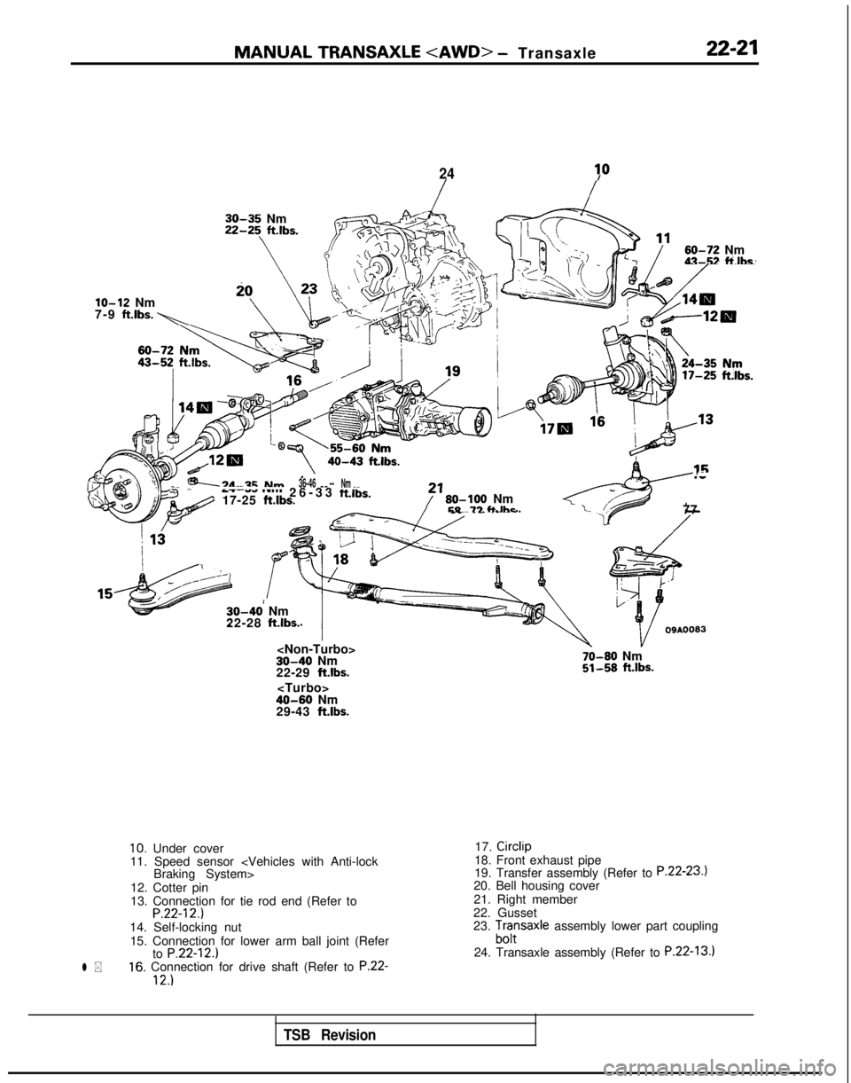
- Transaxle22-21
2430
30-35 Nm 22-25\
ftlbs.
-.
60-72 Nm\‘I..-\)43-52 ti.lhe~
lo-12 Nm
7-9 ft.lbs. 1
40-43 ftlbs..-3d-2FNm
--A 17-25 ft.lbs.
36-46 -_ --Nm _ _.-7.--.--l ‘-“’ 26-33
ftlbs.,f ’
80-106
NmEQ-73 fi Ihr77
30-40’ Nm
22-28 ft.lbs.
22-29 ftlbs.
70-80 Nm51-58 ft.lbs.
29-43 ft.lbs.
l *
10. Under cover
11. Speed sensor
12. Cotter pin
13. Connection for tie rod end (Refer to
P.22-12.)14. Self-locking nut 15. Connection for lower arm ball joint (Refer to
P.22-12.)16. Connection for drive shaft (Refer to P.22-12.)
17. Circlip
18. Front exhaust pipe
19. Transfer assembly (Refer to
P.22-23.120. Bell housing cover
21. Right member
22. Gusset
23.
;f;saxle assembly lower part coupling
24. Transaxle assembly (Refer to
P.22-13.1
TSB Revision
Page 686 of 1273
MANUAL TRANSAXLE
“\
)I
wb
I 1
\
I
1
M#
\\11Aoooo
SERVICE POINTS OF REMOVALM22MBAT
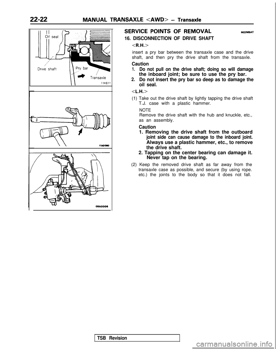
16. DISCONNECTION OF DRIVE SHAFT
insert a pry bar between the transaxle case and the drive
shaft, and then pry the drive shaft from the transaxle.
Caution
1.Do not pull on the drive shaft; doing so will damage
the inboard joint; be sure to use the pry bar.
2.Do not insert the pry bar so deep as to damage the
oil seal.
(1) Take out the drive shaft by lightly tapping the drive shaft T.J. case with a plastic hammer.
NOTE
Remove the drive shaft with the hub and knuckle, etc.,
as an assembly.
Caution
1. Removing the drive shaft from the outboard
joint side can cause damage to the inboard joint.
Always use a plastic hammer, etc., to remove
the drive shaft.
2. Tapping on the center bearing can damage it. Never tap on the bearing.
(2) Keep the removed drive shaft as far away from the transaxle case as possible, and secure (by using rope.
etc.) the joints to the body so that it does not fall.
TSB Revision
Page 687 of 1273
MANUAL TRANSAXLE
TRANSFER
REMOVAL AND INSTALLATION
22-23M22MA.C
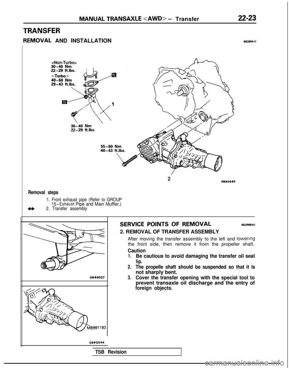
Removal steps
1. Front exhaust pipe (Refer to GROUP15-Exhaust
Pipe and Main Muffler.)2. Transfer assembly
SERVICE POINTS OF REMOVAL MZZMBAU
2. REMOVAL OF TRANSFER ASSEMBLY After moving the transfer assembly to the left and lowenng
the front side, then remove it from the propeller shaft.
Caution
1.Be cautious to avoid damaging the transfer oil seal
lip.
2.The propelle shaft should be suspended so that it is
not sharply bent.09AOO273.Cover the transfer opening with the special tool to
prevent transaxle oil discharge and the entry of-Iforeign objects.
20910095
OQPOO44
TSB Revision
Page 688 of 1273

NOTES
Page 689 of 1273
23-1
AUTOMATIC
TRANSAXLE
CONTENTShl23AA-
GENERALINFORMATION. . . . . . . . . . . . . . . . . . . . . . . . . . . .
SERVICEADJUSTMENTPROCEDURES.....
Drive Shaft OilSealsReplacement...........
KeyInterlockMechanismCheck............... Kickdown
ServoAdjustment ......................
Line Pressure Adjustment .........................
Park/Neutral Position Switch
Adjustment
............................................................
ReducingPressure Adjustment .................
Selector LeverOperation
Check...............
Shift
LockMechanismCheck....................
Speedometer
CableReplacement .............
Throttle-position Sensor Adjustment ..........
TransaxleFluidLevelInspection ...........i...
TransaxleFluidReplacement .....................
Transfer
Oil LevelInspection .....................
Transfer
OilReplacement ..........................
SPECIAL
TOOLS. . . . . . . . . . . . . . . . . . . . . . . . . . . . . . . . . . . . \
. . . . . . .21
SPECIFICATIONS ...........................................19
General Specifications
................................19
Lubricants....................................................20
Torque Specifications .................................20
2TRANSAXLEASSEMBLY
82
92
83
86
88
84
91
83
84
93
92
82
82
82
82
TRANSAXLEASSEMBLY
TRANSAXLE CONTROL. . . . . . . . . . . . . . . . . . . . . . . . . . . . . . .94
TRANSAXLE OIL
COOLERHOSES . . . . . . . . . . . . .100
TRANSFER
. . . . . . . . . . . . . . . . . . . . . . . . . . . . . . . . . . . . \
. . . . . . . . . . . . . . . . .108
TROUBLESHOOTING
....................................
CircuitDiagram...........................................
Converter Stall Test ...................................
Datalink
andTest................................................
E.L.C. 4-speed Automatic Transaxle
ControlComponents
Layout
......................
Element in Use at Each Position
of Selector Lever .......................................
Fail-safe Item ..............................................
Fault Code Description ...............................
OilPressure Tests
.....................................
Shift Patterns ..............................................
Transaxle
Control........................................
22
60
59
26
80
37
32
28
52
37 59
Page 690 of 1273
