MITSUBISHI GALANT 1989 Service Repair Manual
Manufacturer: MITSUBISHI, Model Year: 1989, Model line: GALANT, Model: MITSUBISHI GALANT 1989Pages: 1273, PDF Size: 37.62 MB
Page 651 of 1273
21-1
CLUTCH
CONTENTS
CLUTCH CONTROL. . . . . . . . . . . . . . . . . . . . . . . . . . . . . . . . . . . . \
. . . . .10SPECIFICATIONS. . . . . . . . . . . . . . . ..*...........................2
CLUTCHMASTER CYLINDER. . . . . . . . . . . . . . . . . . . . . . . .12GeneralSpecifications. . . . . . . . . . . . . . . . . . . . . . . . . . . . . . . . . .2
CLUTCH PEDALLubricants . . . . . . . . . . . . . . . . . . . . . . . . . . . . . . .\
. . . . . . . . . . . . . . . . . . . . . . .3. . . . . . . . . . . . . . . . . . . . . . . . . . . . . . . . . . . . \
. . . . . . . . . .7
ServiceSpecifications. . . . . . . . . . . . . . . . . . . . . . . . . . . . . . . . . . .2
CLUTCHRELEASECYLINDER. . . . . . . . . . . . . . . . . . . . . . .13Torque Specifications . . . . . . . . . .._.......................3
SERVICE ADJUSTMENT PROCEDURES . . . . . . . 5TROUBLESHOOTING. . . . . . . . . . . . . . . . . . . . . . . . . . . . . . . . . . . . \
. .4
Bleeding. . . . . . . . . . . . . . . . . . . . . . . . . . . . . . . .6Clutch chatters
Clutch Pedal Inspection and Adjustment . . . .
5Clutch noise
Clutch pedal feels “heavy”
Clutch slips
Gear shift malfunction
CAUTION When
servicing clutch assemblies or com-
ponents for vehicles with SOHC engine
(Up to 1991 models), do NOT create dust
by sanding or by cleaning clutch parts
with a dry brush or with compressed air.
(A water dampened cloth should be used).
The clutch disc contains “Asbestos Fibers”
which can become airborne if dust is
created during service operations. Breath-
ing dust containing “Asbestos Fibers”
may cause serious bodily harm.
Page 652 of 1273
21-2CLUTCH - Specifications
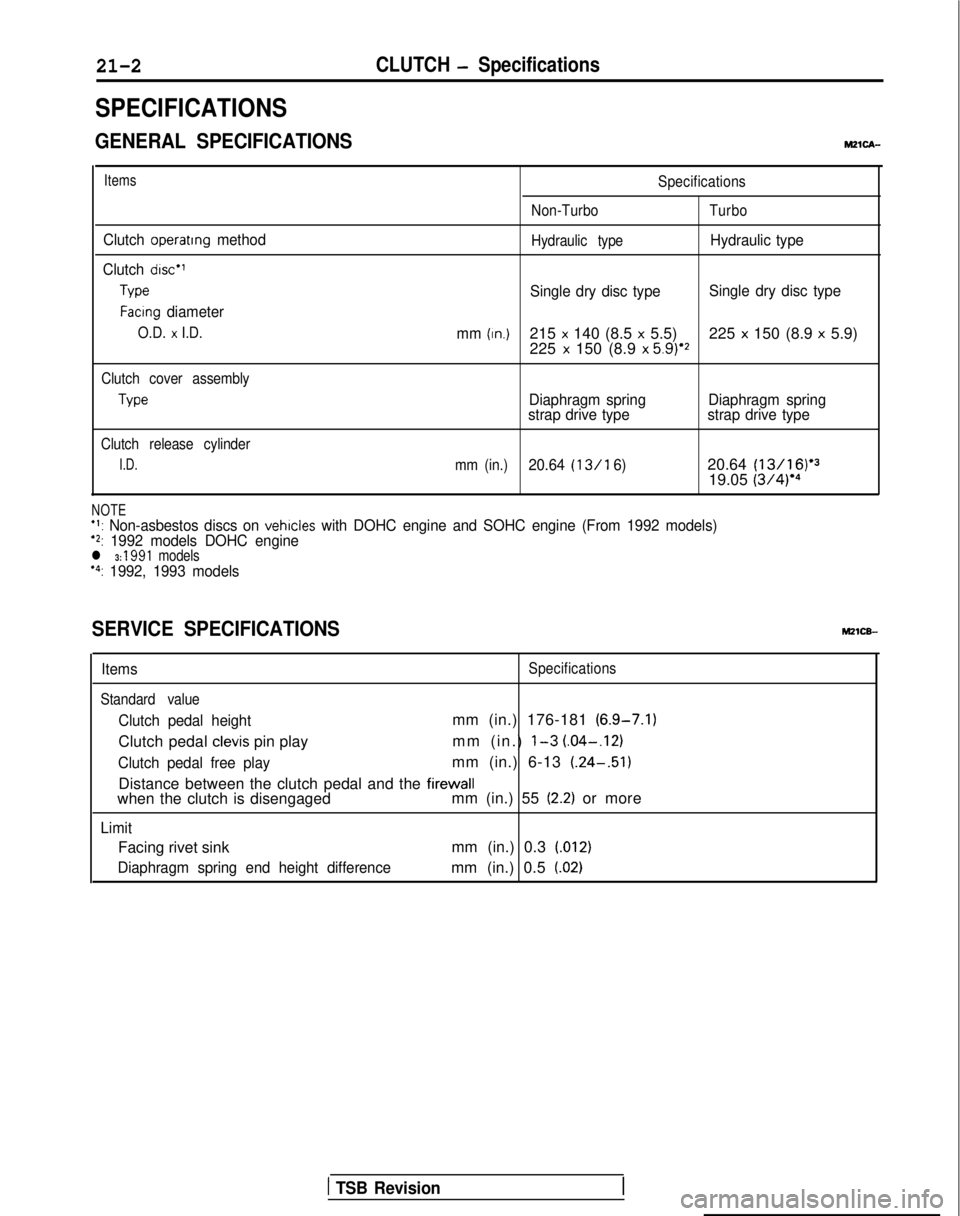
SPECIFICATIONS
GENERAL SPECIFICATIONSMZlCA-
Items
Clutch operattng method
Clutch disc”
Type
Facing diameter
O.D. x I.D.
Specifications
Non-Turbo Turbo
Hydraulic type
Hydraulic type
Single dry disc type Single dry disc type
mm
(In.)215 x 140 (8.5 x 5.5) 225 x 150 (8.9 x 5.9)
225 x 150 (8.9 x 5.9)‘2
Clutch cover assembly
Type
Clutch release cylinder
I.D.
Diaphragm spring Diaphragm spring
strap drive type strap drive type
mm (in.)20.64 (13/l 6)20.64 (13/16)‘3
19.05 (3/4)‘4
NOTE+l: Non-asbestos discs on vehicles with DOHC engine and SOHC engine (From 1992 models)‘2: 1992 models DOHC enginel 3: 1991 models“: 1992, 1993 models
SERVICE SPECIFICATIONS
ItemsSpecifications
Standard value
Clutch pedal heightmm (in.) 176-181 (6.9-7.1)
Clutch pedal
clevis pin play mm (in.) l-3 (.04-.I21
Clutch pedal free playmm (in.) 6-13
(.24-.51)
Distance between the clutch pedal and the
firewallwhen the clutch is disengaged mm (in.) 55 (2.2) or more
Limit
Facing rivet sinkmm (in.) 0.3 1.012)
Diaphragm spring end height differencemm (in.) 0.5 f.02)
1 TSB Revision
Page 653 of 1273
CLUTCH - Specifications21-3
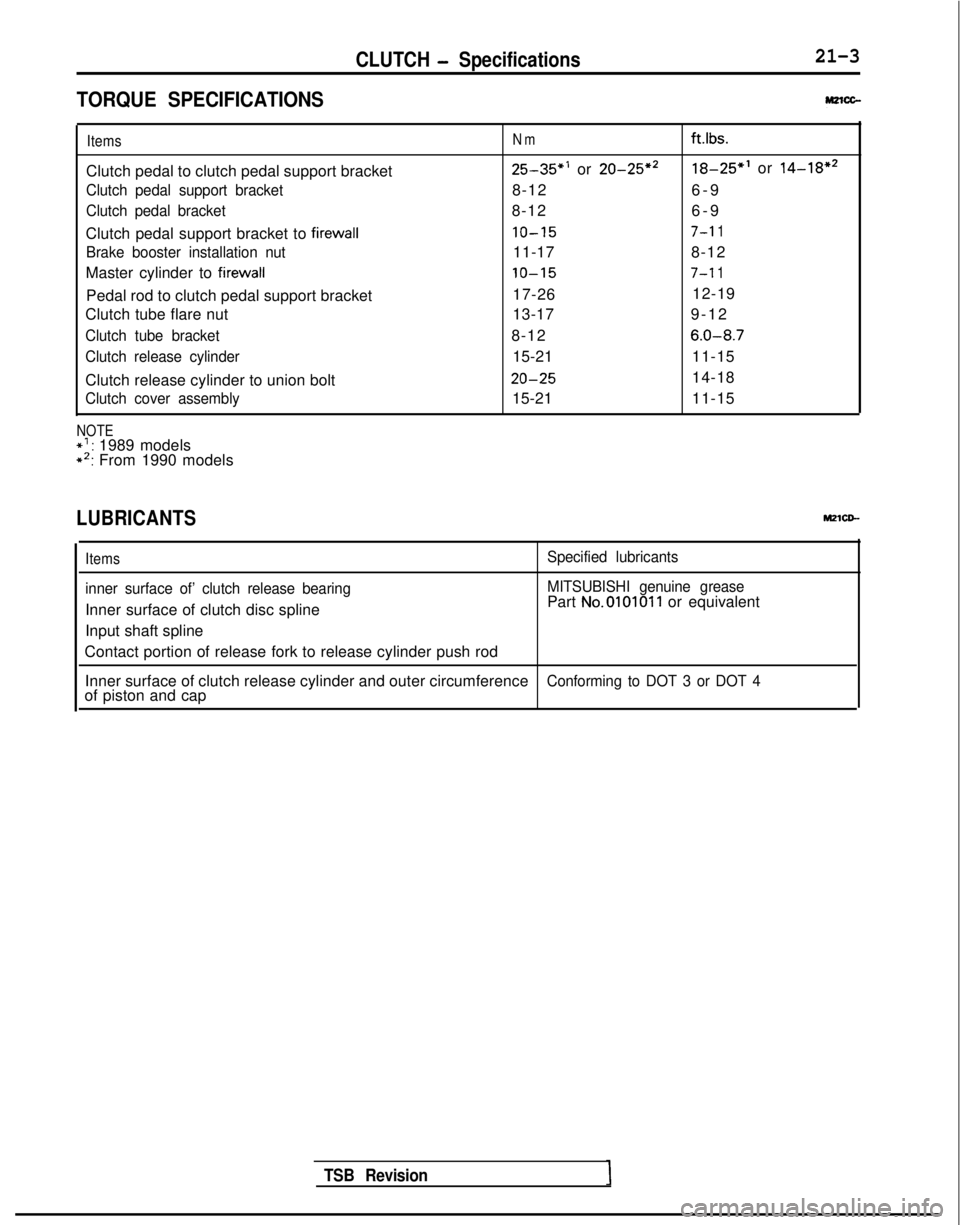
TORQUE SPECIFICATIONSM2lcc-
ItemsNmft.lbs.
Clutch pedal to clutch pedal support bracket25-35”’ or 20-25*218-25”’ or 14-18*2
Clutch pedal support bracket8-12
6-
9
Clutch pedal bracket8-12
6-
9
Clutch pedal support bracket to
firewall10-157-l 1
Brake booster installation nut11-17 8-12
Master cylinder to
firewall10-157-l 1
Pedal rod to clutch pedal support bracket 17-26
12-19
Clutch tube flare nut 13-179-1
2
Clutch tube bracket8-126.0-8.7
Clutch release cylinder15-21
11-15
Clutch release cylinder to union bolt
20-2514-18
Clutch cover assembly15-21 11-15
NOTE*’ : 1989 models*‘: From 1990 models
LUBRICANTSMZlCD-
Items
inner surface of’ clutch release bearing
Inner surface of clutch disc spline
Input shaft spline
Specified lubricants
MITSUBISHI genuine grease
Part No.010101 1 or equivalent
Contact portion of release fork to release cylinder push rod Inner surface of clutch release cylinder and outer circumference
Conforming to DOT 3 or DOT 4of piston and cap
TSB Revision
Page 654 of 1273
CLUTCH - Troubleshootinn
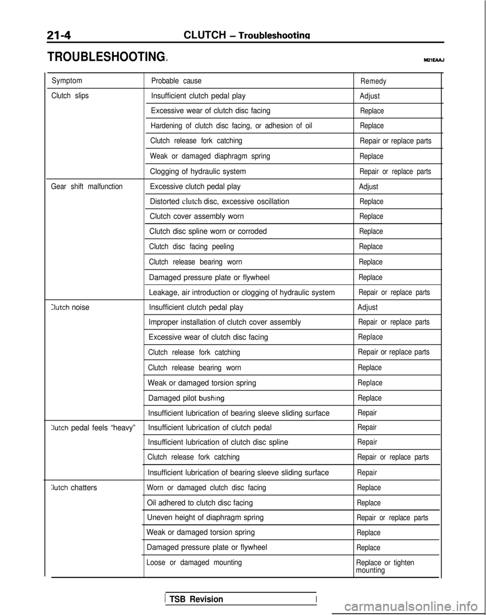
TROUBLESHOOTING
Symptom
Probable causeRemedy
Clutch slipsInsufficient clutch pedal playAdjust
Excessive wear of clutch disc facingReplace
Hardening of clutch disc facing, or adhesion of oilReplace
Clutch release fork catching Repair or replace parts
Weak or damaged diaphragm spring
Replace
Clogging of hydraulic systemRepair or replace parts
Gear shift malfunctionExcessive clutch pedal playAdjust
Distorted clutch disc, excessive oscillationReplace
Clutch cover assembly wornReplace
Clutch disc spline worn or corrodedReplace
Clutch disc facing peelingReplace
Clutch release bearing wornReplace
Damaged pressure plate or flywheelReplace
Leakage, air introduction or clogging of hydraulic systemRepair or replace parts
Iutch noise Insufficient clutch pedal playAdjust
Improper installation of clutch cover assemblyRepair or replace parts
Excessive wear of clutch disc facingReplace
Clutch release fork catching Repair or replace parts
Clutch release bearing worn
Replace
Weak or damaged torsion springReplace
Damaged pilot bushingReplace
Insufficient lubrication of bearing sleeve sliding surfaceRepair
Clutch pedal feels “heavy” Insufficient lubrication of clutch pedalRepair
Insufficient lubrication of clutch disc splineRepair
Clutch release fork catchingRepair or replace parts
Insufficient lubrication of bearing sleeve sliding surfaceRepair
Iutch
chattersWorn or damaged clutch disc facingReplace
Oil adhered to clutch disc facingReplace
Uneven height of diaphragm springRepair or replace parts
Weak or damaged torsion springReplace
Damaged pressure plate or flywheelReplace
Loose or damaged mounting
Replace or tighten
mounting
1 TSB RevisionI
Page 655 of 1273
CLUTCH - Service Adiustment Procedures21-5
Clutch pedal height
Clutch pedal clevispin play
08104,08YO43
Vehicles without
auto-cruise control Vehicles with
auto-cruise control
08A0025
IL\\A- i.14
in.)Nnt,erlock s.y,ityh ,
Clutch
II/ / ?--pedal08AOO41
Clutch pedal free play
08YO43
Distance between the
clutch pedal and the
firewall when theclutch is disengaged
‘5 :: :
*\\\ ;.,
\.
.-‘.* ..,.--. . .:,
eir-
.;
D
l3sFO13
SERVICE ADJUSTMENT PROCEDURES
CLUTCH PEDAL INSPECTION AND ADJUSTM&‘+d+d
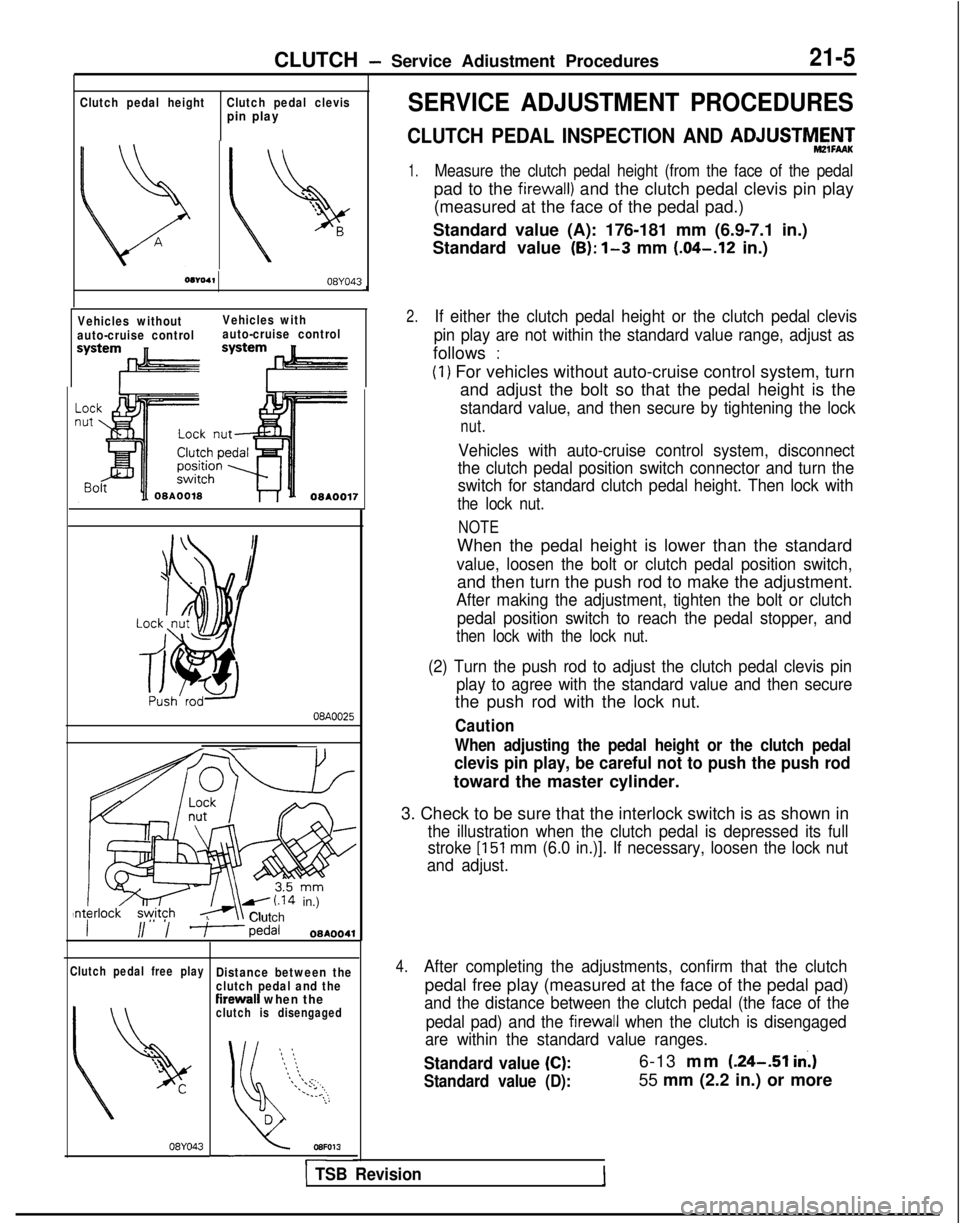
1.Measure the clutch pedal height (from the face of the pedal
pad to the firewall) and the clutch pedal clevis pin play
(measured at the face of the pedal pad.)
Standard value (A): 176-181 mm (6.9-7.1 in.)
Standard value
(B): l-3 mm (.04-.12
in.)
2.If either the clutch pedal height or the clutch pedal clevis
pin play are not within the standard value range, adjust as
follows :
(1) For vehicles without auto-cruise control system, turn and adjust the bolt so that the pedal height is the
standard value, and then secure by tightening the lock
nut.
Vehicles with auto-cruise control system, disconnect
the clutch pedal position switch connector and turn the
switch for standard clutch pedal height. Then lock with
the lock nut.
NOTE
When the pedal height is lower than the standard
value, loosen the bolt or clutch pedal position switch,
and then turn the push rod to make the adjustment.
After making the adjustment, tighten the bolt or clutch
pedal position switch to reach the pedal stopper, and
then lock with the lock nut.
(2) Turn the push rod to adjust the clutch pedal clevis pin play to agree with the standard value and then secure
the push rod with the lock nut.
Caution
When adjusting the pedal height or the clutch pedal
clevis pin play, be careful not to push the push rod
toward the master cylinder.
3. Check to be sure that the interlock switch is as shown in
the illustration when the clutch pedal is depressed its full
stroke
[I51 mm (6.0 in.)]. If necessary, loosen the lock nut
and adjust.
4.After completing the adjustments, confirm that the clutch
pedal free play (measured at the face of the pedal pad)
and the distance between the clutch pedal (the face of the
pedal pad) and the
firewall when the clutch is disengaged
are within the standard value ranges.
Standard value (C):6-13 mm (.24--51 in.)
Standard value (D):55 mm (2.2 in.) or more
1 TSB Revision
Page 656 of 1273
21-6CLUTCH - Service Adjustment Procedures
5.If the clutch pedal free play and the distance between the
clutch pedal and the firewall when the clutch is disengaged
do not agree with the standard values, it is probably the
result of either air in the hydraulic system or a faulty master
cylinder or clutch. Bleed the air, or disassemble and inspect
the master cylinder or clutch.
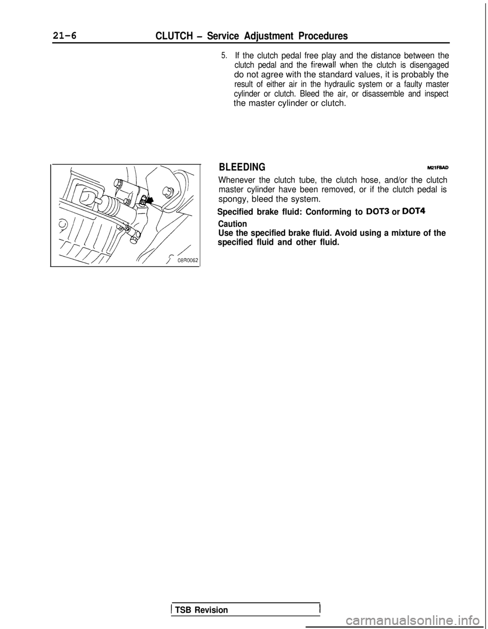
BLEEDINGM2lFBAD
Whenever the clutch tube, the clutch hose, and/or the clutch master cylinder have been removed, or if the clutch pedal is
spongy, bleed the system.
Specified brake fluid: Conforming to DOT3 or DOT4
Caution
Use the specified brake fluid. Avoid using a mixture of the
specified fluid and other fluid.
1 TSB Revision
Page 657 of 1273
CLUTCH - Clutch Pedalm-7
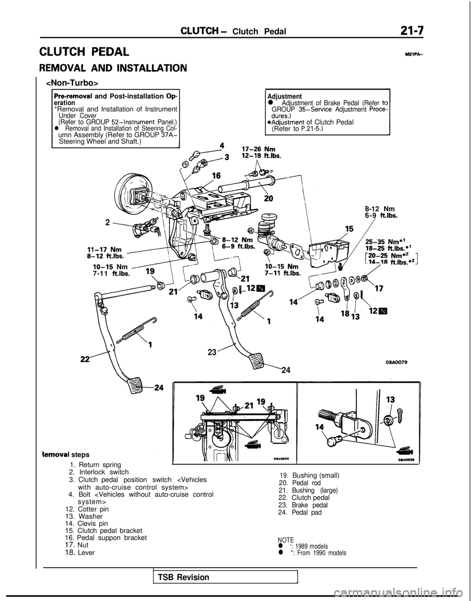
CLUTCH PEDAL
REMOVAL AND INSTALLATION
Pre-removal and Post-installation Operation*Removal and Installation of InstrumentUnder Cover
(Refer to GROUP 52-Instrument Panel.)l Removal and Installation of Steering Col-umn Assembly (Refer to GROUP 37A-Steering Wheel and Shaft.)
Adjustmentl Adjustment of Brake Pedal (Refer tcGROUP 35-Service Adjustment Procedures.)@Adjustment of Clutch Pedal
(Refer to P.21-5.)
MZIPA-
2
8-12 Nm
6-9 ft.lbs.
r:-20-25Nmi12Lib-18ft.lbs.*21lo-15 Nm -7-11 ftlbs.
23
24
09AOO79
Semoval steps
1. Return spring
2. Interlock switch
3. Clutch pedal position switch
4. Bolt
12. Cotter pin
13. Washer
14. Clevis pin
15. Clutch pedal bracket
16. Pedal suppon bracket
17. Nut
18. Lever
19.Bushing (small)20. Pedal rod
21.
22. Bushing (large)
Clutch pedal23.
Brake pedal
24. Pedal pad
NOTEl ‘: 1989 modelsl *: From 1990 models
TSB Revision
Page 658 of 1273
21-8CLUTCH- Clutch Pedal
Pre-removal and Post-installation Op-eration*Removal and Installation of instrumentUnder Cover
(Refer to GROUP 52-Instrument Panel.)*Removal and Installation of Steering Col-
umn Assembly (Refer to GROUP 37A-
Steering Wheel and Shaft.)
Adjustmentl Adjustment of Brake Pedal (Refer to
GROUP 35-Service Adjustment Proce-dures.)*Adjustment of Clutch Pedal
(Refer to P.21-5.1
3
22
“,24 00AOO82
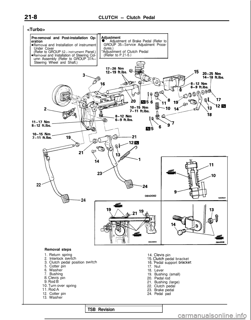
Removal steps
I. Return spring 14. Clevis pin15. @fch pedal bracket2.Interlock switch3. Clutch pedal position switcn5.Cotter pin6.Washer7.Bushing;: E;;i; pin
;
;: poTrer spring
12.Cotter pin13.Washer 16. Pedal support bracket
17.Nut18.Lever19.Bushing (small)20.Pedal rod21.Bushing (large)22.Clutch pedal23.Brake pedal24.
Pedal pad
TSB Revision
Page 659 of 1273
CLUTCH - Clutch Pedal21-9
INSPECTIONM!ZlPCAG
l Check the pedal shaft and bushing for wear.
l Check the clutch pedal for bend or torsion.
l Check the return spring for damage or deterioration.
l Check the pedal pad for damage or wear.
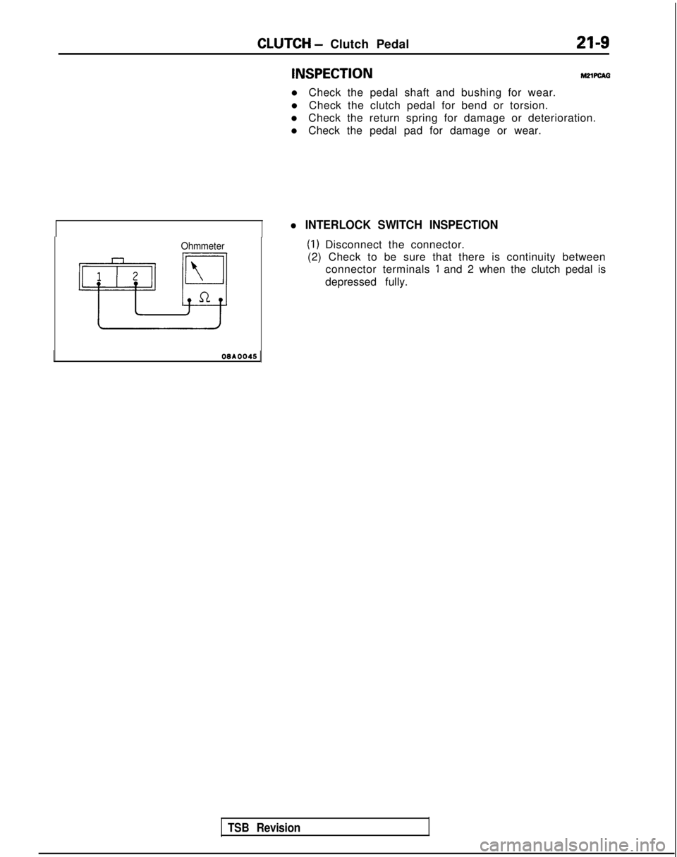
l INTERLOCK SWITCH INSPECTION
Ohmmeter(1) Disconnect the connector.
(2) Check to be sure that there is continuity between connector terminals
1 and 2 when the clutch pedal is
depressed fully.
OGAOO45
TSB Revision
Page 660 of 1273
21-10CLUTCH - Clutch Control
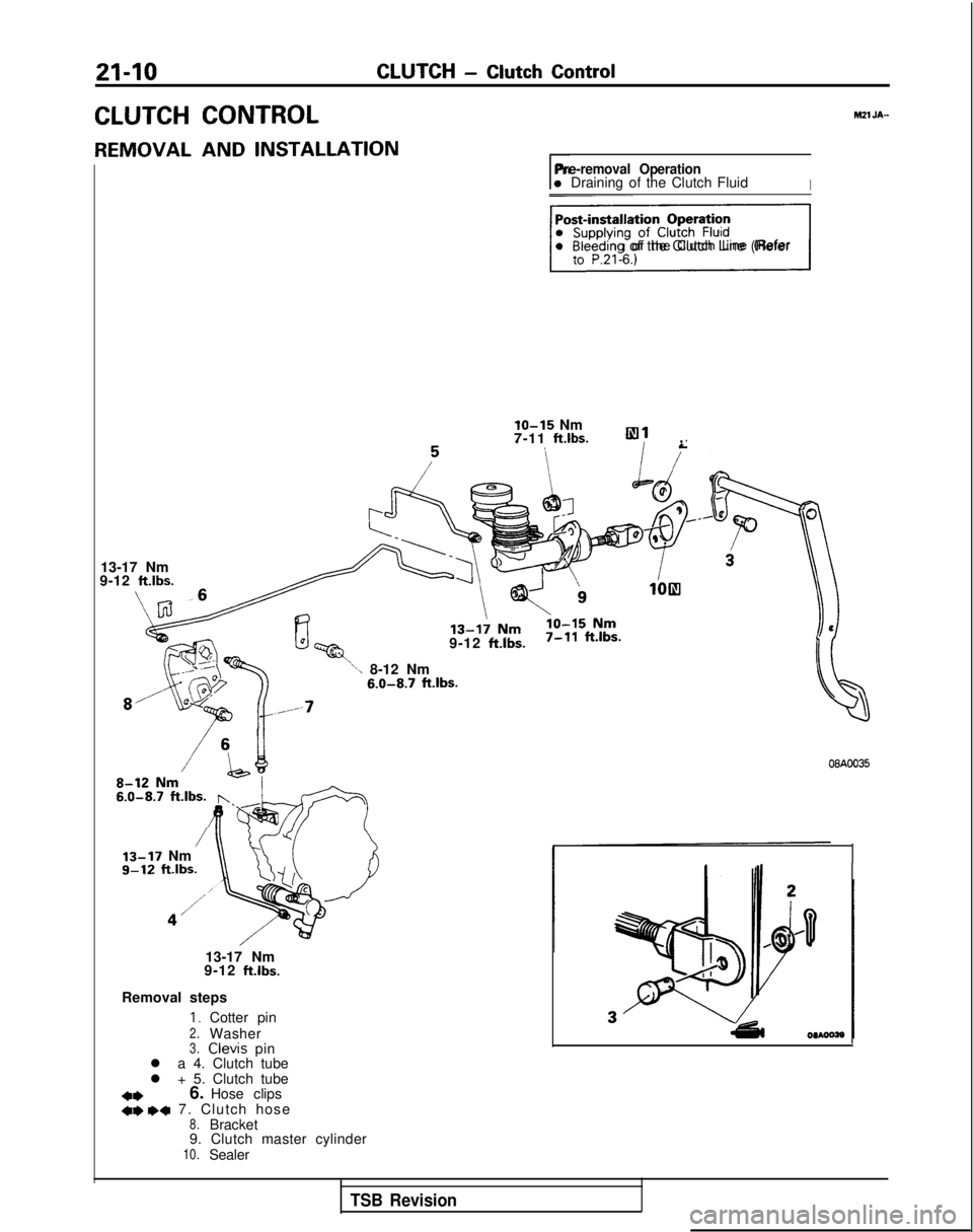
CLUTCH CONTROLh121 JA-
REMOVAL AND INSTALLATION
rPre-removal Operationl Draining of the Clutch FluidI
piigsql Bleeding of the Clutch Line (Refer
lo-15 Nm
7-11 ft.lbs.,
13-17 Nm
9-12
ft.lbs.
9-12 ft.lbs.
\-\ 8-12 Nm 6.0-8.7
ft.lbs.
/ 13-17
Nm
9-12 ftlbs.
13-17 Nm
9-12
ft.lbs.
Removal steps
I. Cotter pin2.Washer3. Clevis
pin
l a 4. Clutch tube
l + 5. Clutch tube
a*6. Hose clips*I) wq 7. Clutch hose8.Bracket
9. Clutch master cylinder
10.Sealer
08A0035
TSB Revision