MITSUBISHI GALANT 1989 Service Repair Manual
Manufacturer: MITSUBISHI, Model Year: 1989, Model line: GALANT, Model: MITSUBISHI GALANT 1989Pages: 1273, PDF Size: 37.62 MB
Page 731 of 1273
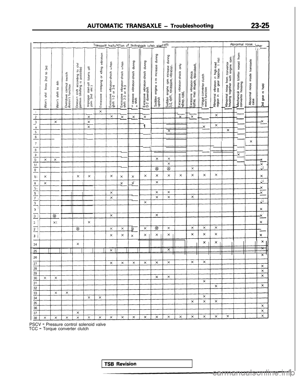
AUTOMATIC TRANSAXLE
- Troubleshooting23-25
r star
P =
<
zzGsEa
c”65
srBZzi;4
1
1
Y-
a
s
s-
7
ii-
s-
3-1
z-
3
1_:5s
5
f-
d
1i
‘I3
E*aOm5s;K
;$2zIrg:,8
EP2.2
$2-
If
E:
p2zz0om,c .Gis:75’‘5$5oz28-
-
-
7-
_/-
4
X
?I-
92L”$ElE0
-
zmz
“$
P::g=f,i?Ppzz?$5.- -CE$2
gsi
-
= 0
0752=o-+u$Z
52
gEEO-
- nsaxl’
-
;
4
i?
3
b
$
:
b
?
mk?
::
w
nalfu-
f3::2?gmyQr0.3-J$GbG
LF!‘,
SO” c-
f35eL?g_mc?PV,L 0
.FnEC+8r35-
x-
,hlft-r-
if5 -0
::2Bg
z
5
Pz=$5
3
4
- ck la
- fte
T
z2
B5t8s,-55
P$%88,3d-
x
-i1
Is,
c
5
‘0mc
gi?
DEEf
ge‘2
c”d
p$
“=‘
EiumTNm,ci )th(
l-
jhO#
X-
-
-
-
XX
X-X-
-
-
g,-
X
-.
I
-
5cIpcg;UCa, 22,$ ‘cG$68-
gz
?&SiEss
555m$g
IcE-
?5g
26a2
_’s
8fsz
gD$;i058-cw3
5zYE8g$nso’51b’F m
asz fis-$2x-uo
E(1
9
-z
N
E2
2m-
z-
r 0
35fc2 .ss:!0=3;Pg-
xx--x-X-X-
-
-
-
-
x-
-
-
-
-
-
-
-
6F-
X
X
xX-
-
-
PSCV = Pressure control solenoid
TCC = Torque converter clutch
I-
X
TX
X
X
X
x- X
X
X-
X
-
X
valve
TSB Revision
Page 732 of 1273
23-26AUTOMATIC TRANSAXLE - Troubleshooting
HOT
TFA0715
AW
D
TFA0700
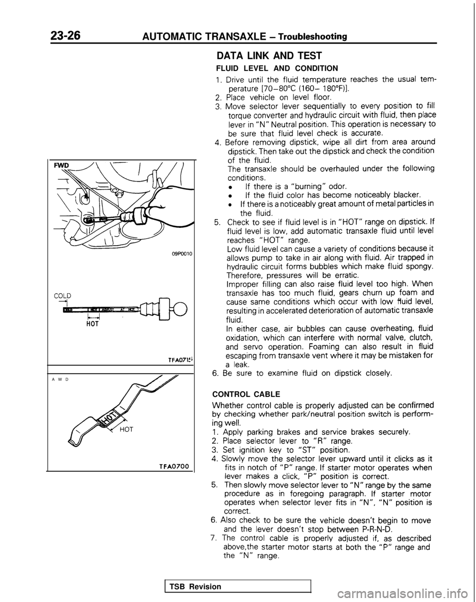
DATA LINK AND TEST
FLUID LEVEL AND CONDITION
1. Drive until the
fluid
temperature
reaches the
usual tem-
perature
[70-80°C (160- 18O”F)l.
2. Place
vehicle
on level floor.
3. Move
selector
lever sequentially
to
every
position
to fill
torque
converter
and hydraulic circuit
with fluid,
then
place
lever in “N” Neutral position.
This operation is necessary
t0
be sure that fluid
level check is accurate.
4. Before
removing
dipstick,
wipe all dirt from area around
dipstick.
Then take out
the
dipstick
and check the
condition
of the
fluid.
The
transaxle
should be overhauled under the following
conditions.
l If there
is a “burning” odor.
l If the
fluid
color
has become
noticeably
blacker.
lIf there
is a noticeably
great
amount
of metal particles in
the
fluid.
5.Check to
see if fluid
level is in “HOT” range on dipstick.
If
fluid
level is low, add automatic
transaxle
fluid
until level
reaches “HOT” range.
Low
fluid
level can cause a variety of
conditions
because it
allows
pump
to
take
in air along with fluid. Air trapped in
hydraulic circuit
forms
bubbles
which
make fluid
spongy.
Therefore,
pressures
will be erratic. Improper filling
can also raise fluid level too
high. When
transaxle
has too
much fluid,
gears churn up foam and
cause same
conditions
which occur with low fluid
level, resulting
in accelerated deterioration
of
automatic
transaxle
fluid.
In
either
case, air bubbles
can cause overheating,
fluid
oxidation,
which can interfere
with normal valve, clutch,
and
servo
operation.
Foaming can also result
in fluid
escaping
from
transaxle
vent where it
may be mistaken
for
a leak.
6. Be
sure to
examine
fluid
on dipstick
closely.
CONTROL CABLE
Whether control
cable is properly
adjusted
can be confirmed
by
checking
whether park/neutral
position
switch is perform-
ing
well.
1.
Apply
parking brakes and service
brakes securely.
2. Place
selector
lever
to
“R” range.
3. Set ignition
key to
“ST” position.
4.
Slowly
move
the
selector
lever
upward
until it
clicks as it
fits in
notch of “P” range. If starter
motor
operates
when
lever makes a click, “P”
position
is correct.
5.Then slowly
move
selector
lever to “N” range by
the
same
procedure as in foregoing
paragraph. If starter
motor
operates
when selector
lever
fits in ‘IN”, “N” position
is correct.
6.
Also check to be sure the
vehicle
doesn’t
begin to move
and
the
lever
doesn’t
stop
between
P-R-N-D.
7. The control
cable is properly
adjusted if, as described
above,the
starter
motor
starts
at both the
“P” range and the
“N” range.
TSB Revision
Page 733 of 1273
AUTOMATIC TRANSAXLE
- Troubleshootin
g
23-27
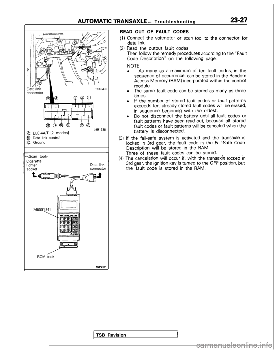
READ OUT OF FAULT CODES
(1)
Connect
the
voltmeter or scan tool
to the
connector
for data
link.
ItI ITi i i I_ . . c - 7 IIIL:‘!‘/‘!’ ‘j’:‘J
6666S@16R13388,: ELC-4PJT 12 modes1
@: Data link control
@: Ground
(2) Read
the
output fault
codes. Then
follow the remedy
procedures according to the
“Fault
Code Description”
on the following
page.
NOTE
l As many
as a maximum
of ten fault
codes, in the
sequence
of
occurrence,
can be stored
in the
Random Access
Memory (RAM) incorporated
within the
control
module.
l
The same
fault
code can be stored
as many
as three
times.
l
If the number
of stored
fault
codes or
fault
patterns
exceeds
ten,
already
stored
fault
codes
will be erased,
in
sequence
beginning
with the
oldest.
lDo
not
disconnect the
battery
until all fault
codes or
fault
patterns
have
been read out, because al! stored
fault
codes
or fault
patterns
will
be canceled when
the
battery is
disconnected.
~ ~~
(3)
If the
fail-safe
system is activated
and the
transaxle
is
locked in 3rd gear, the fault
code in the
Fail-Safe Code Description
will be stored
in the
RAM.
Three of these fault
codes can be stored.. ,.
Cigarette
lighter
socket
1
(4) The cancelation
will
occur if, with the
transaxle
locked rn 3rd
gear, the ignition
key is turned
to
the
OFF position,
but
Data link
connector the
fault code is stored
in the
RAM.
MB991 341
\
ROM back
16PO151
TSB Revision
Page 734 of 1273
23-28AUTOMATIC TRANSAXLE - Troubleshooting ’
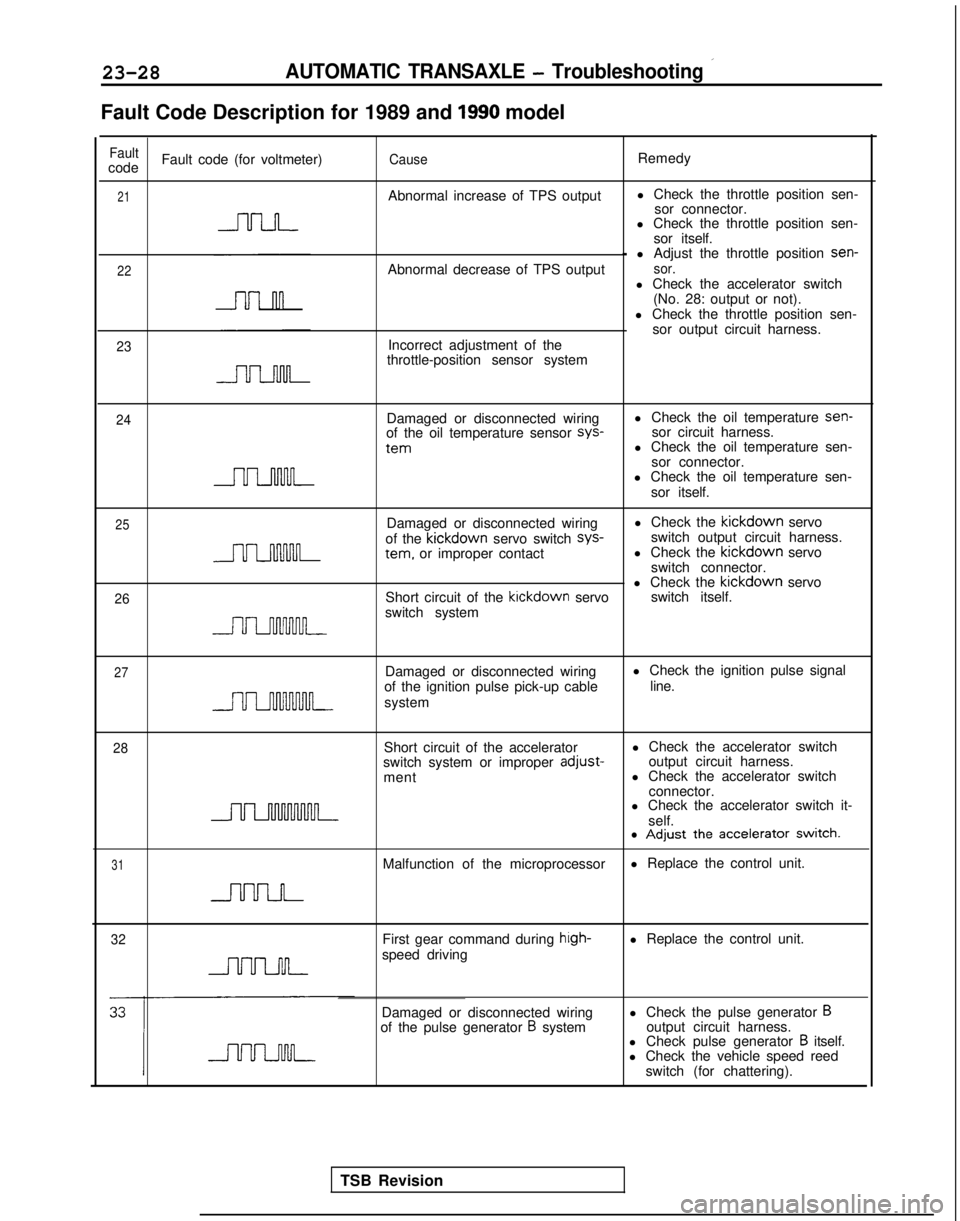
Fault Code Description for 1989 and 1990 model
FaultcodeFault code (for voltmeter)CauseRemedy
21Abnormal increase of TPS output
l Check the throttle position sen-
sor connector.
l Check the throttle position sen-
sor itself.
22
23
- l Adjust the throttle position sen-
Abnormal decrease of TPS outputsor.l Check the accelerator switch (No. 28: output or not).
l Check the throttle position sen- sor output circuit harness.
Incorrect adjustment of the
throttle-position sensor system
24Damaged or disconnected wiring
of the oil temperature sensor sys-
tern
l Check the oil temperature sen-
sor circuit harness.
l Check the oil temperature sen-
sor connector.
l Check the oil temperature sen-
sor itself.
25
26
Damaged or disconnected wiring l Check the kickdown
servo
of the kickdown
servo switch sys-
switch output circuit harness. tern.
or improper contact l Check the kickdown
servo
switch connector.
l Check the kickdown
servo
Short circuit of the kickdown
servo switch itself.
switch system
27Damaged or disconnected wiring
of the ignition pulse pick-up cable
system l Check the ignition pulse signal
line.
28Short circuit of the accelerator
switch system or improper adjust-
ment l Check the accelerator switch
output circuit harness.
l Check the accelerator switch
connector.
l Check the accelerator switch it-
self.
31
l Adjust the accelerator switch.
Malfunction of the microprocessor l Replace the control unit.
32First gear command during hrgh-speed drivingl Replace the control unit.
Damaged or disconnected wiring
of the pulse generator
B system l Check the pulse generator Boutput circuit harness.
l Check pulse generator B itself.
l Check the vehicle speed reed
switch (for chattering).
TSB Revision
Page 735 of 1273
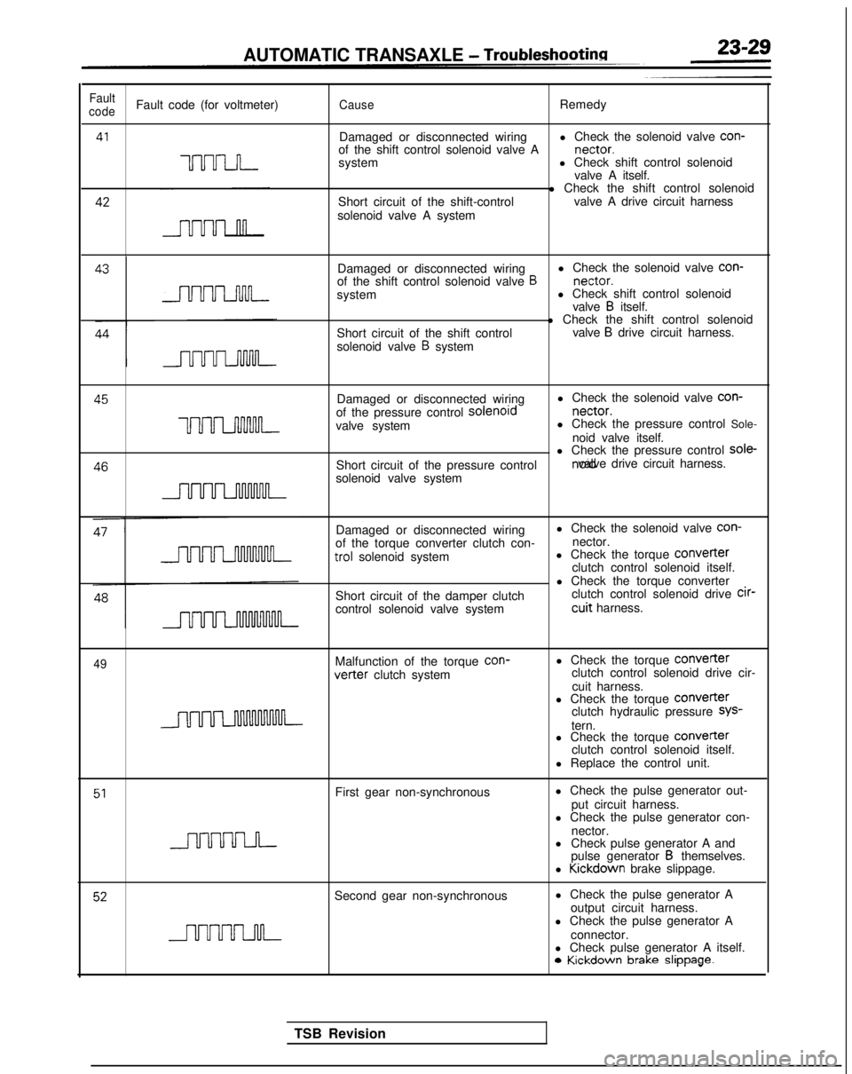
AUTOMATIC TRANSAXLE - Troubleshootina
Fault
codeFault code (for voltmeter)CauseRemedy
41
UUU-LJ-I-
Damaged or disconnected wiring l Check the solenoid valve con-
of the shift control solenoid valve A nectar.
system l Check shift control solenoid
valve A itself. 42
Short circuit of the shift-control
solenoid valve A system l Check the shift control solenoid
valve A drive circuit harness
Damaged or disconnected wiring l Check the solenoid valve con-
of the shift control solenoid valve
B nectar.
system l Check shift control solenoid
valve
B itself.
Short circuit of the shift control
solenoid valve
B system l Check the shift control solenoid
valve
B drive circuit harness. 45
Damaged or disconnected wiringl Check the solenoid valve con-
of the pressure control solenord nectar.
uuuLnnnM-valve system
l Check the pressure control Sole-
noid valve itself. 46
l Check the pressure control sole-
Short circuit of the pressure control noid valve drive circuit harness.
solenoid valve system
Damaged or disconnected wiring
of the torque converter clutch con- trol
solenoid system
Short circuit of the damper clutch
control solenoid valve system l Check the solenoid valve con-
nector.
l Check the torque COnVeIter
clutch control solenoid itself.
l Check the torque converter clutch control solenoid drive cir-
cuit harness.
49Malfunction of the torque
con-vetter clutch system
l Check the torque
Converterclutch control solenoid drive cir-
cuit harness.
l Check the torque
COnVeITerclutch hydraulic pressure SYS-
tern.
l Check the torque COnVerter
clutch control solenoid itself.
l Replace the control unit.
51First gear non-synchronous l Check the pulse generator out-
put circuit harness.
l Check the pulse generator con-
nector.
l Check pulse generator A and
pulse generator
B themselves.
l Kickdown
brake slippage.
52Second gear non-synchronous l Check the pulse generator A
output circuit harness.
l Check the pulse generator A
connector.
l Check pulse generator A itself. 0
Kickdown brake slippage.
TSB Revision
Page 736 of 1273
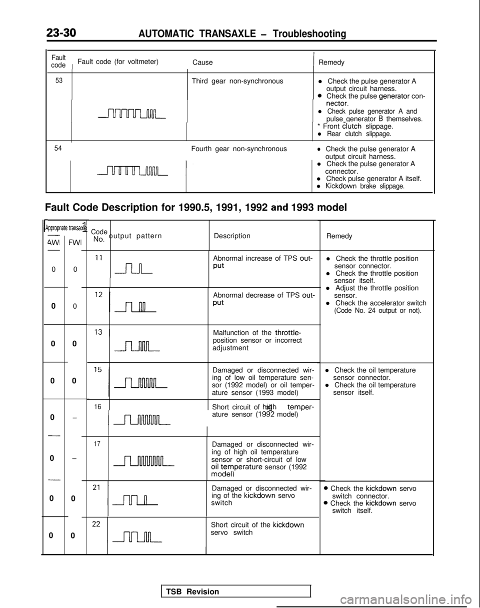
23-30AUTOMATIC TRANSAXLE - Troubleshooting
l Check the pulse generator Aoutput circuit harness.
0Check the pulse venerator
con- nectar.
-l Check pulse generator A andpulse generator B themselves.
Fault Code Description for 1990.5, 1991, 1992
and 1993 model
rP
Fault
code
IFault code (for voltmeter) CauseIRemedy
53Third gear non-synchronous
* Front clutch
slippage.
l Rear clutch slippage.
54
Fourth gear non-synchronouslCheck the pulse generator A
output circuit harness.
l Check the pulse generator A
connector.
l Check pulse generator A itself.
l Kickdown brake slippage.
ipproprlate transa-
4Wl-
0
0
0
0
0
-
0
-
0
0
FWI
0
0
0
0
-
-
0
0
xle1CodeNo, output pattern Description
Remedy
‘I n
Abnormal increase of TPS out-
Put
Abnormal decrease of TPS out-
Put
l Adjust the throttle position
sensor.
l Check the accelerator switch
(Code No. 24 output or not).
Malfunction of the throttle-position sensor or incorrect
adjustment
Damaged or disconnected wir-
ing of low oil temperature sen- l Check the oil temperature
sensor connector.
sor (1992 model) or oil temper- l Check the oil temperature
ature sensor (1993 model) sensor itself.
16Short circuit of hiah oil temDer-
ature sensor (1992 model) ’
17Damaged or disconnected wir-
ing of high oil temperature
sensor or short-circuit of low
oiz;eyIperature sensor (1992
Damaged or disconnected wir-
ing of the kickdown
servo
switch
Short circuit of the kickdown
servo switch l Check the throttle position
sensor connector.
l Check the throttle position sensor itself.
D Check the kickdown
servo
switch connector.
B Check the kickdown
servo
switch itself.
TSB Revision
Page 737 of 1273
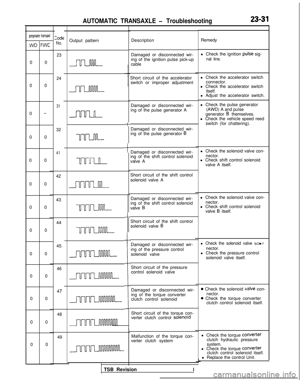
AUTOMATIC TRANSAXLE - Troubleshooting23-31
CodeNo.propriate transaxl
,WD FWC
Output pattern Description Remedy
Damaged or disconnected wir-
ing of the ignition pulse pick-up
cable l Check the ignition
puke sig-
nal line.
Short circuit of the accelerator
l Check the accelerator switch
switch or improper adjustment connector.
l Check the accelerator switch
itself.
l Adjust the accelerator switch.
Damaged or disconnected wir-
ing of the pulse generator A
+
l Check the pulse generator
(AWD) A and pulse
generator
B themselves.
l Check the vehicle speed reed
switch (for chattering).
Damaged or disconnected wir-
ing of the pulse generator
B
tDamaged or disconnected wir-
ing of the shift control solenoid
valve A l Check the solenoid valve con-
nector.
l Check shift control solenoid
valve A itself.
Short circuit of the shift control
solenoid valve A
Damaged or disconnected wir-
ing of the shift control solenoid
valve
B
l Check the solenoid valve con- nector.
-L
l Check shift control solenoidvalve B itself.
Short circuit of the shift control
solenoid valve
B
i
Damaged or disconnected wir-
ing of the pressure control solenoid valvel Check the solenoid valve con-
nector.
l Check the pressure control
solenoid valve itself.
Short circuit of the pressure
control solenoid valve
Damaged or disconnected wir-
ing of the torque converter
clutch control solenoid
0 Check the solenoid valve con-nector.0 Check the torque converter clutch control solenoid itself.
Short circuit of the torque con-
verter clutch control solenord
Malfunction of the torque con-
verter clutch system l Check the torque COnVefter
clutch hydraulic pressure
system.
0 0
0 0
0
-
0 0
0 0
0 00 00 0
0 0 0 0
0 0
0 00 0
23
24
31
32
41
n
uuuul
UUUI n
42
nn
43
uum
44 45
uum
46 47
48
TSB RevisionI
l Check the torque
Converter
clutch control solenoid itself.
l Replace the control Unit.
49
Page 738 of 1273
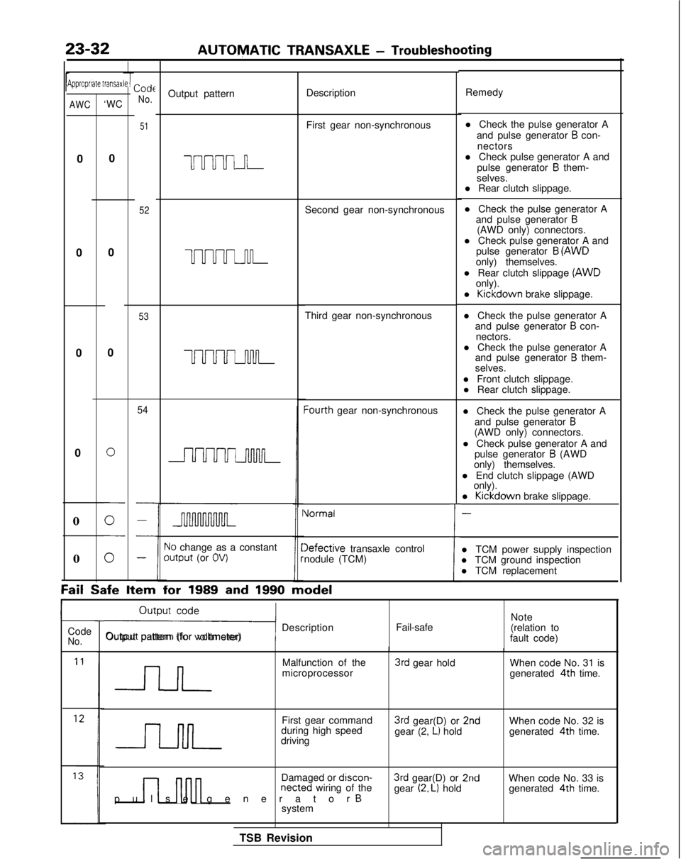
23-32AUTOMATIC TRANSAXLE
- Troubleshooting
Jipproprrate transaxCode
No.Output pattern Description
Remedy
51First gear non-synchronous
uuuul n
52Second gear non-synchronous l Check the pulse generator A
and pulse generator
B con-
nectors
l Check pulse generator A and pulse generator
B them-
selves.
l Rear clutch slippage.
l Check the pulse generator A and pulse generator
B(AWD only) connectors.
l Check pulse generator A and pulse generator
B (AWD
only) themselves.
l Rear clutch slippage (AWD
only).
l Kickdown
brake slippage.
l Check the pulse generator A and pulse generator
B con-
nectors.
l Check the pulse generator A and pulse generator
B them-
selves.
l Front clutch slippage. l Rear clutch slippage.
l Check the pulse generator A and pulse generator
B(AWD only) connectors.
l Check pulse generator A and pulse generator
B (AWD
only) themselves.
l End clutch slippage (AWD only).
l Kickdown
brake slippage.
-
l TCM power supply inspection
l TCM ground inspection
l TCM replacement
AWC‘WC
0
0 0
0
0
UUUUJ-u-l-
53Third gear non-synchronous
0
0
UUUUuwL
54Iourth gear non-synchronous
0
i
Vormal
10 change as a constantoutput (or OV)Iefective transaxle control
nodule (TCM)
0
Fail Safe
Item for
1989 and 1990 model
ri Description
Output pattern (for voltmeter) Fail-safeNote
(relation to
fault code)
Code
No.
Malfunction of the
microprocessor3rd gear hold When code No. 31 is
generated 4th
time.
First gear command
during high speed
driving
3rd gear(D) or 2ndgear (2, L) hold When code No. 32 is
generated 4th
time.
n nnn
Damaged or discon-netted wiring of the
pulse generator Bsystem
3rd gear(D) or 2ndgear (2. L) hold When code No. 33 is
generated 4th
time.
TSB Revision
Page 739 of 1273
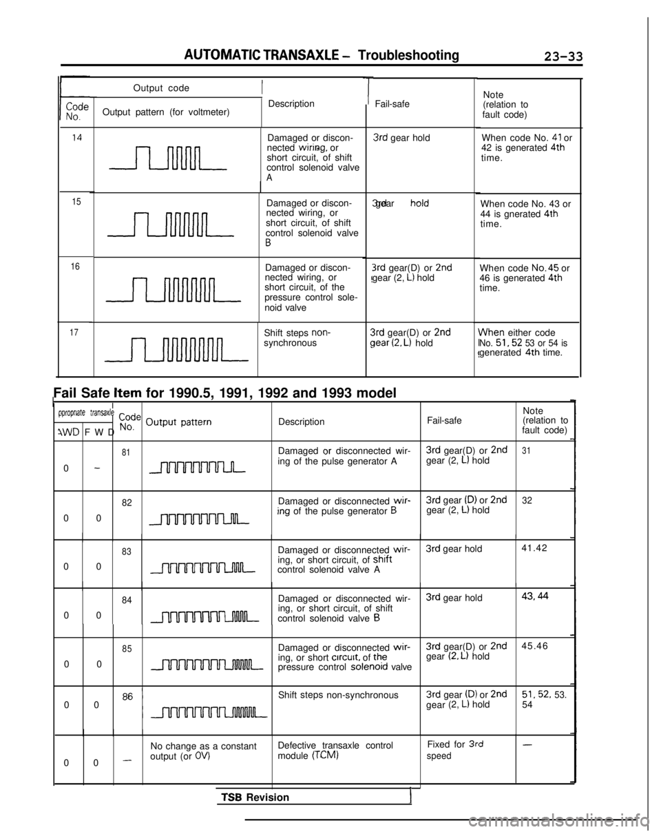
AUTOMATIC TRANSAXLE - Troubleshooting23-33
15
16
17
Output code
Output pattern (for voltmeter) Description
Damaged or discon-
nected
wiring, or
short circuit, of shift
control solenoid valve
A
Damaged or discon-
nected wiring, or
short circuit, of shift
control solenoid valve
B
Damaged or discon-
nected wiring, or
short circuit, of the
pressure control sole-
noid valve
Shift steps
non-synchronous
TFail-safe 3rd
gear hold 3rd gear hold
3rd gear(D) or 2ndgear (2, L) hold
3rd gear(D) or 2ndJear (2, L) hold
Note
(relation to
fault code)
When code No.
41 or
42 is generated 4th
time.
When code No. 43 or
44 is gnerated 4th
time.
When code No.45
or
46 is generated 4th
time.
flhen either codeNo. 51,52 53 or 54 isgenerated 4th
time.
Fail Safe
Item for 1990.5, 1991, 1992 and 1993 modelI
pproprlate transaxle Code Output patternNote
Description Fail-safe
(relation to
IWD FWD No.fault code)
81Damaged or disconnected wir- 3rd
gear(D) or 2nd31
0 -ing of the pulse generator A
gear (2, L) hold
82Damaged or disconnected wir- 3rd
gear (D) or 2nd32
0 0;ng of the pulse generator Bgear (2, L) hold
83Damaged or disconnected wir-
3rd
gear hold 41.42
0 0
ming, or short circuit, of shaftcontrol solenoid valve A
84Damaged or disconnected wir- 3rd
gear hold43,44
0 0m
ing, or short circuit, of shift
control solenoid valve B
85
Damaged or disconnected wir- 3rd
gear(D) or 2nd
45.46
0 0ming, or short crrcurt, of tne
gear (2. L) hold
pressure control solenord
valve
0 0 Shift
steps
non-synchronous 3rd
gear
(D) or 2nd51,52,53.gear (2, L) hold
54
No change as a constant Defective transaxle control Fixed for 3rd
-
0 0 -output (or OV)module (TCM)
speed
ITSB Revision
Page 740 of 1273
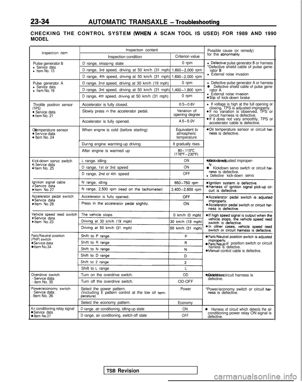
23-34AUTOMATIC TRANSAXLE - Troubleshooting
CHECKING THE CONTROL SYSTEM (WHEN
A SCAN TOOL IS USED) FOR 1989 AND 1990
MODEL
Pulse generator Al Service datal Item No. 1’9
Throttle positron sensorTPS)m Service dataD Item No. 21
I!(
(44
c44
I!.,
I(,
\,4
:44 C
.
.
F.
.
A00
D range, stopprng state 0 rpml Defectrve pulse generator B or harness
D range, 3rd speed, driving at 50 km/h (31 mph) 1.600-2.000
rpm*Defective shield cable of pulse gene-
rator B
D range, 4th speed, drivrng at 50 km/h (31 mph) 1.600-2.000
rpml External noise invasion
D range. 2nd speed, driving at 30 km/h (19 mph) 0 rpml Defective pulse generator A or harness
D range, 3rd speed, driving at 50 km/h (31 mph) 1.400-1.800
rpml Defective shield cable of pulse gene-rator A
D range, 4th speed, drivrng at 50 km/h (31 mph) 0 rpml External noise Invasion *Slip
of kick-down brake
Accelerator is fully closed. 0.5-0.6V
l If voltage is high at the full opening or
Slowly press In the accelerator pedal.Variatron of
closing, TPS is adjusted improperly.
opening degreeelf no variation is observed, TPS or
circuit harness is defective.
Accelerator is fully opened.
4.5-5.ovelf it does not vary smoothly, TPS or
accelerator cable is defective. Xl temperature sensor
) Servtce data) Item No. 24
When engtne is cold (before starting)
Equivalent toatmospheric
temperature *Oil
temperature sensor or circuit har-ness is defective.
cickdown servo switch) Servrce data1 Item No. 25
Durrng engine warming-up driving
After engine is warmed up
L range. idling
D range, 1st or 3rd speed
D range, 2nd or 4th speed
It gradually rises.
80- 110°C(176”F-230°F)
ON *Kick-down servo IS adjusted improper-
ONIV.l Kickdown servo switch or circuit har-
OFFness is defective.l Defectivekick-down
servo
bItem No.34 alposition switch or circuitharness is defective.*Manual
control cable is defective.
Iverdnve switch1 Servrce data1 item No. 35
‘owedeconomy swatch‘Servrce data
Item No. 36 Shift to
L range
Turn on the overdrive switch.
Turn off the overdrive switch.
Select the power pattern. (Including
E pattern control at the low oil tem-perature)
L
OD
OD-OFF
Power moverdrive switch or circuit harness is
defective.
*Power/economy switch or circuit har-ness is defective.
Select the economy pattern.
Economy
.ir conditioning relay signalService dataD range. air conditioning, idling-up stateONl Harness of circuit which detects the air
Item No.37D range, air conditioning, switch-off stateOFFconditioning power relay ON signal isdefective.
Inspectron ttemInspectron content
Inspection conditionPossible cause (or remedy)
Criterion value for the abnormalrty
Pulse generator Bl Service datal Item No. 13
TSB Revision