ECU MITSUBISHI LANCER 2005 Workshop Manual
[x] Cancel search | Manufacturer: MITSUBISHI, Model Year: 2005, Model line: LANCER, Model: MITSUBISHI LANCER 2005Pages: 788, PDF Size: 45.98 MB
Page 540 of 788
TROUBLESHOOTING
HEATER, AIR CONDITIONER AND VENTILATION55-56
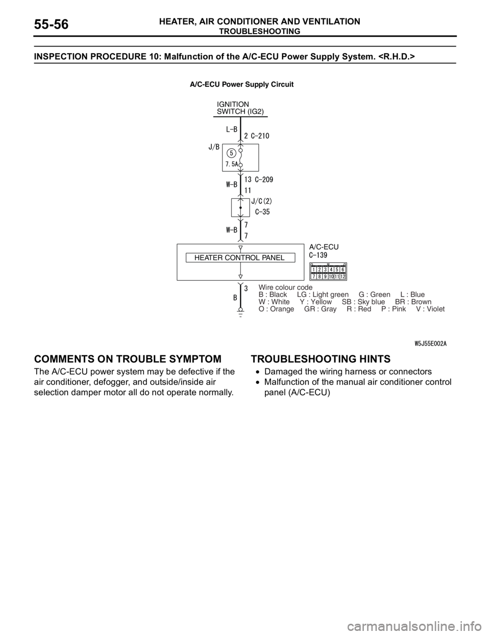
INSPECTION PROCEDURE 10: Malfunction of the A/C-ECU Power Supply System.
COMMENTS ON TROUBLE SYMPTOM
The A/C-ECU power system may be defective if the
air conditioner, defogger, and outside/inside air
selection damper motor all do not operate normally.
TROUBLESHOOTING HINTS
•Damaged the wiring harness or connectors
•Malfunction of the manual air conditioner control
panel (A/C-ECU)
IGNITION
SWITCH (IG2)
HEATER CONTROL PANELA/C-ECU
Wire colour code
B : Black LG : Light green G : Green L : Blue
W : White Y : Yellow SB : Sky blue BR : Brown
O : Orange GR : Gray R : Red P : Pink V : Violet
A/C-ECU Power Supply Circuit
Page 541 of 788
TROUBLESHOOTING
HEATER, AIR CONDITIONER AND VENTILATION55-57
DIAGNOSIS
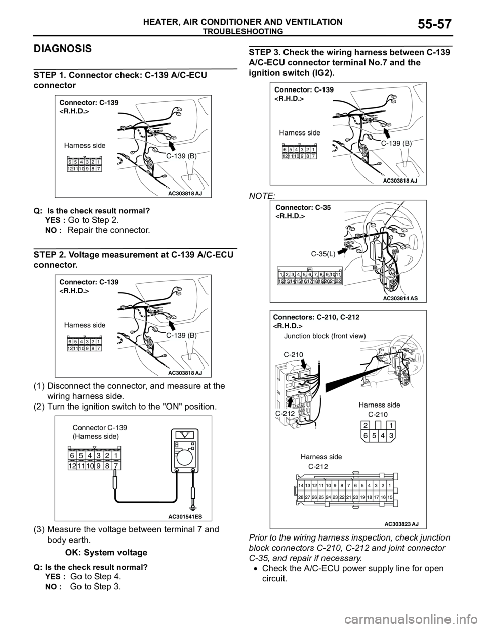
STEP 1. Connector check: C-139 A/C-ECU
connector
Q: Is the check result normal?
YES :
Go to Step 2.
NO : Repair the connector.
STEP 2. Voltage measurement at C-139 A/C-ECU
connector.
(1) Disconnect the connector, and measure at the
wiring harness side.
(2) Turn the ignition switch to the "ON" position.
(3) Measure the voltage between terminal 7 and
body earth.
OK: System voltage
Q: Is the check result normal?
YES :
Go to Step 4.
NO : Go to Step 3.
STEP 3. Check the wiring harness between C-139
A/C-ECU connector terminal No.7 and the
ignition switch (IG2).
NOTE:
Prior to the wiring harness inspection, check junction
block connectors C-210, C-212 and joint connector
C-35, and repair if necessary.
•Check the A/C-ECU power supply line for open
circuit.
AC303818
Connector: C-139
AJ
Harness side
C-139 (B)
11 12657 8 9 103 421
AC303818
Connector: C-139
AJ
Harness side
C-139 (B)
11 12657 8 9 103 421
AC301541ES
Connector C-139
(Harness side)
11 12
65
7 8 9 10
3 421
AC303818
Connector: C-139
AJ
Harness side
C-139 (B)
11 12657 8 9 103 421
AC303814
Connector: C-35
AS
C-35(L)
AC303823
Junction block (front view)
Connectors: C-210, C-212
C-210 Harness side
C-212
C-210
AJ
C-212
Harness side
Page 542 of 788
TROUBLESHOOTING
HEATER, AIR CONDITIONER AND VENTILATION55-58
Q: Is the check result normal?
YES :
The trouble can be an intermittent
malfunction (Refer to GROUP 00, How to
Cope with Intermittent Malfunction P.00-5).
NO : Repair the wiring harness.
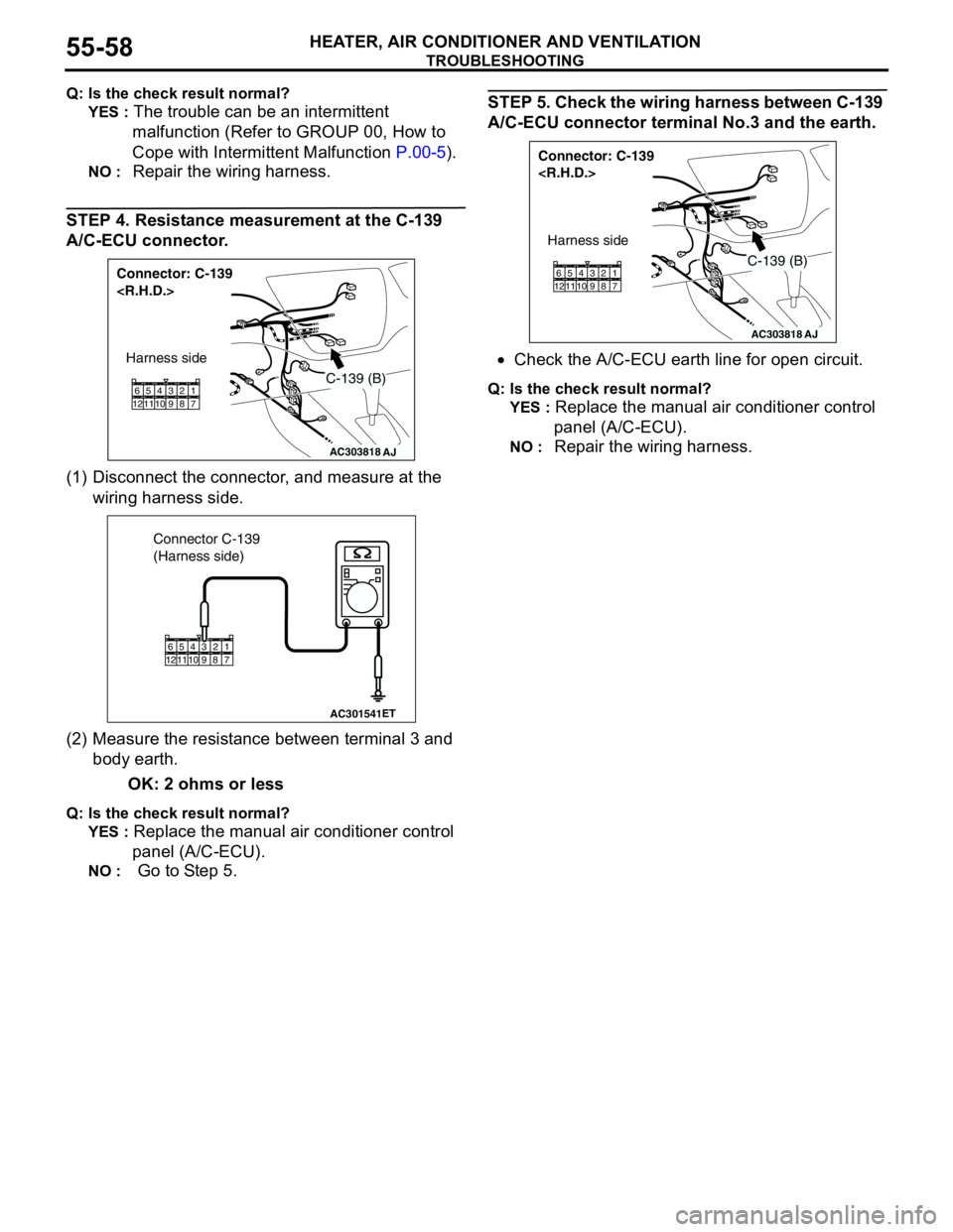
STEP 4. Resistance measurement at the C-139
A/C-ECU connector.
(1) Disconnect the connector, and measure at the
wiring harness side.
(2) Measure the resistance between terminal 3 and
body earth.
OK: 2 ohms or less
Q: Is the check result normal?
YES :
Replace the manual air conditioner control
panel (A/C-ECU).
NO : Go to Step 5.
STEP 5. Check the wiring harness between C-139
A/C-ECU connector terminal No.3 and the earth.
•Check the A/C-ECU earth line for open circuit.
Q: Is the check result normal?
YES :
Replace the manual air conditioner control
panel (A/C-ECU).
NO : Repair the wiring harness.AC303818
Connector: C-139
AJ
Harness side
C-139 (B)
11 12657 8 9 103 421
AC301541ET
Connector C-139
(Harness side)
11 12657 8 9 103 421
AC303818
Connector: C-139
AJ
Harness side
C-139 (B)
11 12657 8 9 103 421
Page 543 of 788
TROUBLESHOOTING
HEATER, AIR CONDITIONER AND VENTILATION55-59
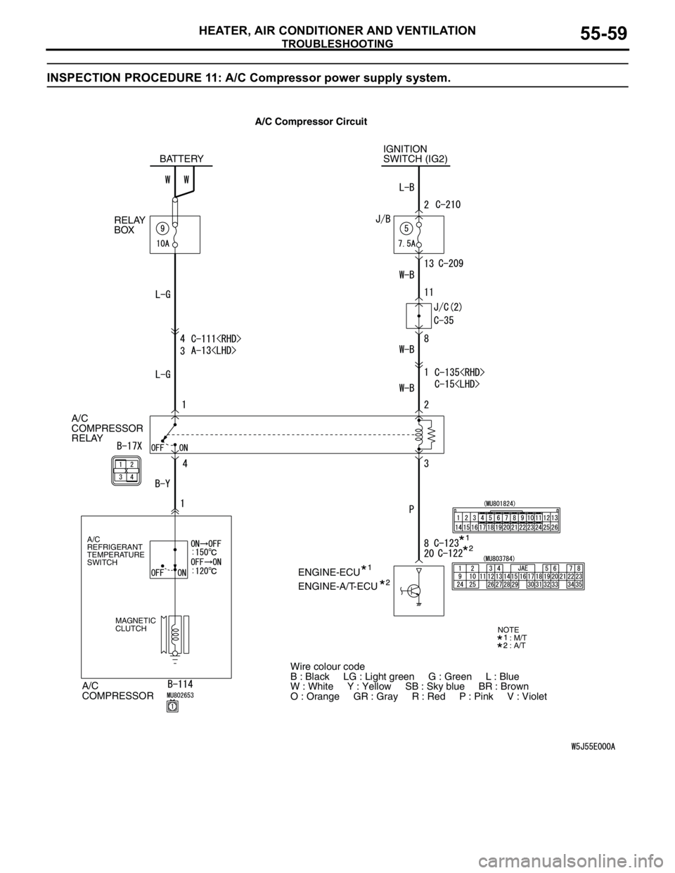
INSPECTION PROCEDURE 11: A/C Compressor power supply system.
A/C
COMPRESSOR
RELAY
A/C
COMPRESSOR
A/C
REFRIGERANT
TEMPERATURE
SWITCH
MAGNETIC
CLUTCH
IGNITION
SWITCH (IG2)
ENGINE-ECU BATTERY
RELAY
BOX
ENGINE-A/T-ECU
Wire colour code
B : Black LG : Light green G : Green L : Blue
W : White Y : Yellow SB : Sky blue BR : Brown
O : Orange GR : Gray R : Red P : Pink V : Violet
: M/T
: A/TNOTE
A/C Compressor Circuit
Page 549 of 788
TROUBLESHOOTING
HEATER, AIR CONDITIONER AND VENTILATION55-65
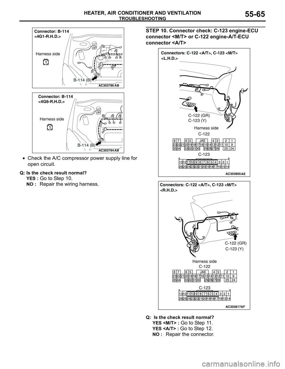
•Check the A/C compressor power supply line for
open circuit.
Q: Is the check result normal?
YES :
Go to Step 10.
NO : Repair the wiring harness.
STEP 10. Connector check: C-123 engine-ECU
connector
connector
Q: Is the check result normal?
YES
Go to Step 11.
YES : Go to Step 12.
NO : Repair the connector.
AC303786
Connector: B-114
<4G1-R.H.D.>
AB
Harness side
B-114 (B)
AC303794
Connector: B-114
<4G6-R.H.D.>
AB
Harness side
B-114 (B)
AC303805
Connectors: C-122 , C-123
C-122 (GR)
C-123 (Y)
C-122 Harness side
C-123
AE
AC303817
Connectors: C-122 , C-123
AF
C-122C-122 (GR)
C-123 (Y)
C-123 Harness side
Page 550 of 788
TROUBLESHOOTING
HEATER, AIR CONDITIONER AND VENTILATION55-66
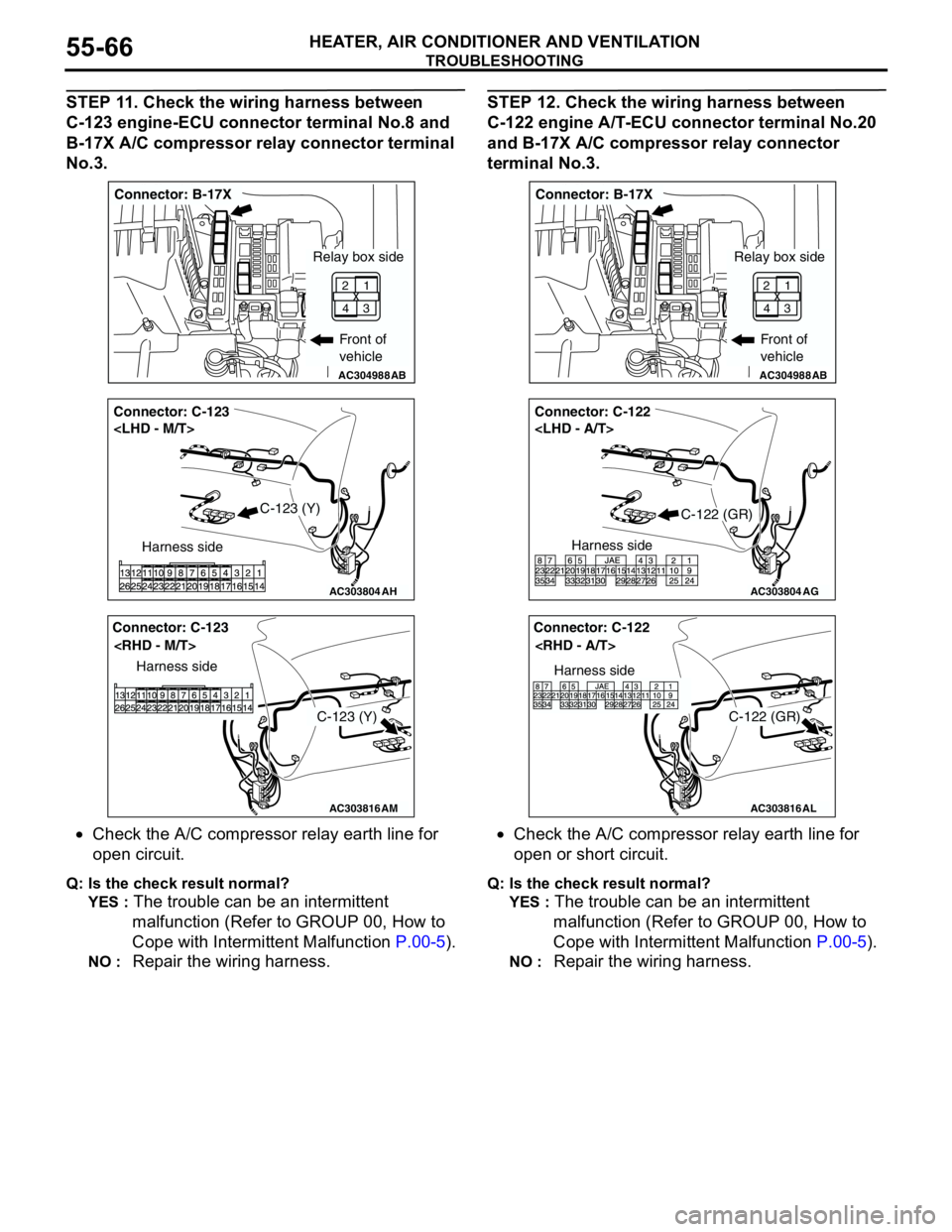
STEP 11. Check the wiring harness between
C-123 engine-ECU connector terminal No.8 and
B-17X A/C compressor relay connector terminal
No.3.
•Check the A/C compressor relay earth line for
open circuit.
Q: Is the check result normal?
YES :
The trouble can be an intermittent
malfunction (Refer to GROUP 00, How to
Cope with Intermittent Malfunction P.00-5).
NO : Repair the wiring harness.
STEP 12. Check the wiring harness between
C-122 engine A/T-ECU connector terminal No.20
and B-17X A/C compressor relay connector
terminal No.3.
•Check the A/C compressor relay earth line for
open or short circuit.
Q: Is the check result normal?
YES :
The trouble can be an intermittent
malfunction (Refer to GROUP 00, How to
Cope with Intermittent Malfunction P.00-5).
NO : Repair the wiring harness.
AC304988AB
Connector: B-17X
Front of
vehicle
1
3 2
4
Relay box side
AC303804
Connector: C-123
AH
Harness side
C-123 (Y)
AC303816
Connector: C-123
AM
Harness side
C-123 (Y)
AC304988AB
Connector: B-17X
Front of
vehicle
1
3 2
4
Relay box side
AC303804
Connector: C-122
AG
Harness side
C-122 (GR)
AC303816
Connector: C-122
AL
Harness side
C-122 (GR)
Page 551 of 788
TROUBLESHOOTING
HEATER, AIR CONDITIONER AND VENTILATION55-67
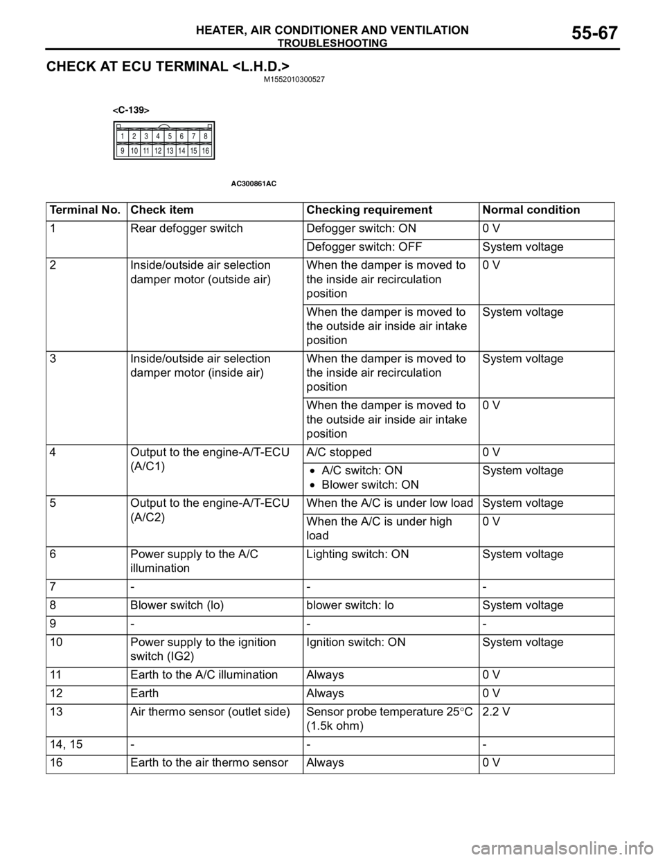
CHECK AT ECU TERMINAL
12
345
678
9 10111213141516
AC300861AC
Terminal No. Check item Checking requirement Normal condition
1 Rear defogger switch Defogger switch: ON 0 V
Defogger switch: OFF System voltage
2 Inside/outside air selection
damper motor (outside air)When the damper is moved to
the inside air recirculation
position0 V
When the damper is moved to
the outside air inside air intake
positionSystem voltage
3 Inside/outside air selection
damper motor (inside air)When the damper is moved to
the inside air recirculation
positionSystem voltage
When the damper is moved to
the outside air inside air intake
position0 V
4 Output to the engine-A/T-ECU
(A/C1)A/C stopped 0 V
•A/C switch: ON
•Blower switch: ONSystem voltage
5 Output to the engine-A/T-ECU
(A/C2)When the A/C is under low load System voltage
When the A/C is under high
load0 V
6 Power supply to the A/C
illuminationLighting switch: ON System voltage
7---
8 Blower switch (lo) blower switch: lo System voltage
9---
10 Power supply to the ignition
switch (IG2)Ignition switch: ON System voltage
11 Earth to the A/C illumination Always 0 V
12 Earth Always 0 V
13 Air thermo sensor (outlet side) Sensor probe temperature 25°C
(1.5k ohm)2.2 V
14, 15 - - -
16 Earth to the air thermo sensor Always 0 V
Page 552 of 788
TROUBLESHOOTING
HEATER, AIR CONDITIONER AND VENTILATION55-68
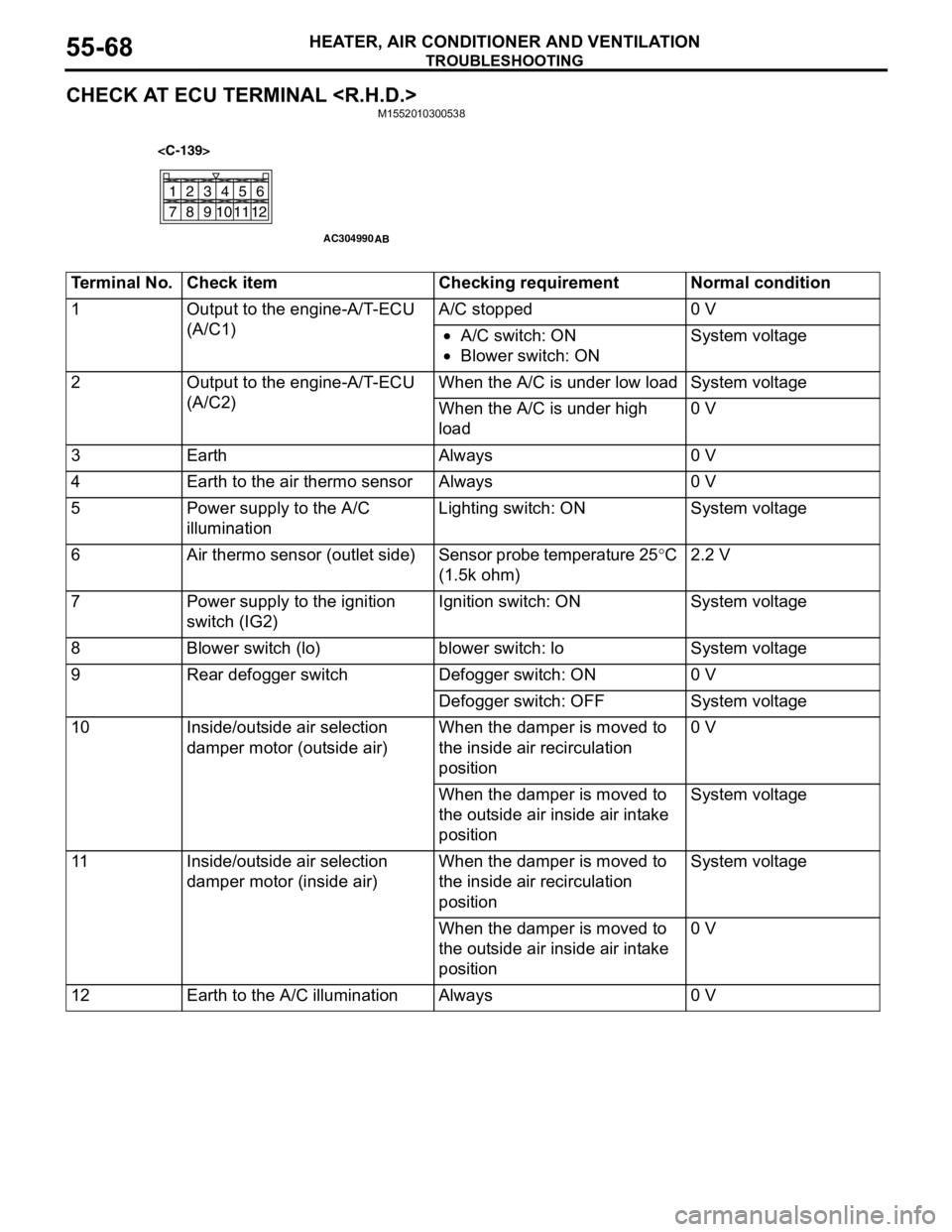
CHECK AT ECU TERMINAL
21
78
6 534
11
10912
AC304990
AB
Terminal No. Check item Checking requirement Normal condition
1 Output to the engine-A/T-ECU
(A/C1)A/C stopped 0 V
•A/C switch: ON
•Blower switch: ONSystem voltage
2 Output to the engine-A/T-ECU
(A/C2)When the A/C is under low load System voltage
When the A/C is under high
load0 V
3 Earth Always 0 V
4 Earth to the air thermo sensor Always 0 V
5 Power supply to the A/C
illuminationLighting switch: ON System voltage
6 Air thermo sensor (outlet side) Sensor probe temperature 25°C
(1.5k ohm)2.2 V
7 Power supply to the ignition
switch (IG2)Ignition switch: ON System voltage
8 Blower switch (lo) blower switch: lo System voltage
9 Rear defogger switch Defogger switch: ON 0 V
Defogger switch: OFF System voltage
10 Inside/outside air selection
damper motor (outside air)When the damper is moved to
the inside air recirculation
position0 V
When the damper is moved to
the outside air inside air intake
positionSystem voltage
11 Inside/outside air selection
damper motor (inside air)When the damper is moved to
the inside air recirculation
positionSystem voltage
When the damper is moved to
the outside air inside air intake
position0 V
12 Earth to the A/C illumination Always 0 V
Page 562 of 788
HEATER CONTROL ASSEMBLY AND A/C SWITCH
HEATER, AIR CONDITIONER AND VENTILATION55-78
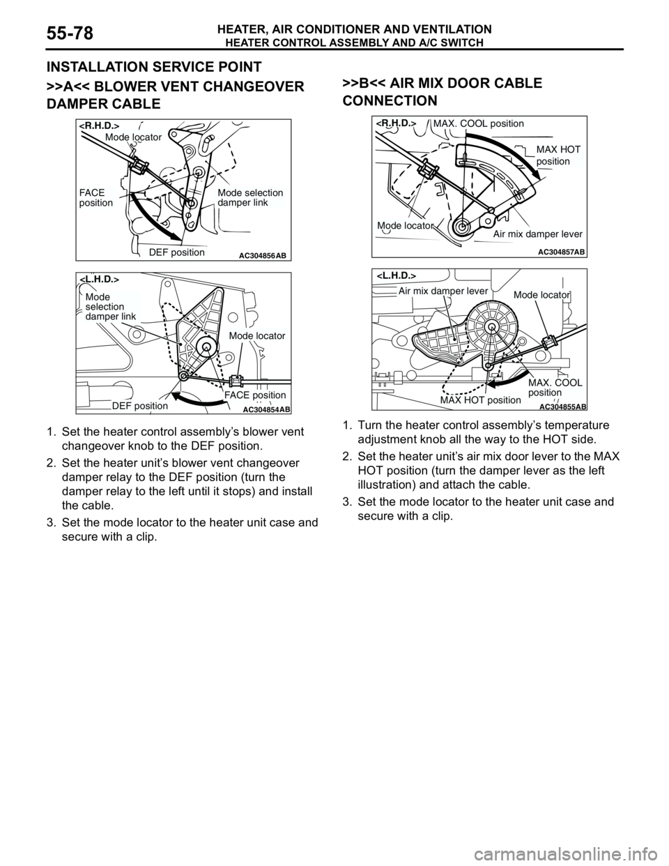
INSTALLATION SERVICE POINT
>>A<< BLOWER VENT CHANGEOVER
DAMPER CABLE
1. Set the heater control assembly’s blower vent
changeover knob to the DEF position.
2. Set the heater unit’s blower vent changeover
damper relay to the DEF position (turn the
damper relay to the left until it stops) and install
the cable.
3. Set the mode locator to the heater unit case and
secure with a clip.
>>B<< AIR MIX DOOR CABLE
CONNECTION
1. Turn the heater control assembly’s temperature
adjustment knob all the way to the HOT side.
2. Set the heater unit’s air mix door lever to the MAX
HOT position (turn the damper lever as the left
illustration) and attach the cable.
3. Set the mode locator to the heater unit case and
secure with a clip.
AC304856DEF position
FACE
position
AB
Mode selection
damper link
Mode locator
AC304854DEF positionFACE position
AB
Mode
selection
damper link
Mode locator
AC304857
MAX HOT
position
MAX. COOL position
AB
Air mix damper leverMode locator
AC304855MAX HOT position
MAX. COOL
position
AB
Air mix damper leverMode locator
Page 563 of 788
HEATER CONTROL ASSEMBLY AND A/C SWITCH
HEATER, AIR CONDITIONER AND VENTILATION55-79
INSPECTIONM1552014300927
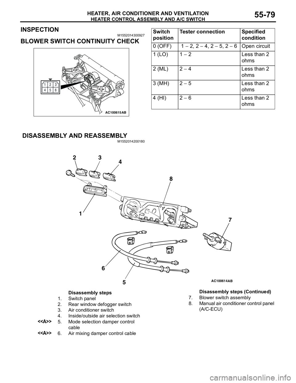
BLOWER SWITCH CONTINUITY CHECK
DISASSEMBLY AND REASSEMBLY
M1552014200180
12
6 3
45
AC100615AB
Switch
positionTester connection Specified
condition
0 (OFF) 1 − 2, 2 − 4, 2 − 5, 2 − 6 Open circuit
1 (LO) 1 − 2 Less than 2
ohms
2 (ML) 2 − 4 Less than 2
ohms
3 (MH) 2 − 5 Less than 2
ohms
4 (HI) 2 − 6 Less than 2
ohms
AC100614
1 23
4
5 67 8
AB
Disassembly steps
1. Switch panel
2. Rear window defogger switch
3. Air conditioner switch
4. Inside/outside air selection switch
<>5. Mode selection damper control
cable
<>6. Air mixing damper control cable7. Blower switch assembly
8. Manual air conditioner control panel
(A/C-ECU) Disassembly steps (Continued)